Note: Descriptions are shown in the official language in which they were submitted.
CA 02789671 2014-04-04
. .._ .
APPARATUS AND METHOD FOR ENDOSCOPIC SUBMUCOSAL
DISSECTION
[0001] This paragraph intentionally left blank.
TECHNICAL FIELD
[0002] This invention generally relates to medical devices and in
particular to an
apparatus, kit and method for endoscopic submucosal dissection using an
injectable
solution.
BACKGROUND
[0003] Minimally invasive medical procedures are performed in various
passageways in the body using elongated instruments inserted through natural
orifices
or small surgical openings. In some procedures, it is desirable to treat some
diseases
using en bloc tissue removal through an elongate device, for example removing
tissue
lesions or polyps.
[0004] In some procedures, such as endoscopic submucosal dissection
(ESD), a
solution may be submucosally injected between layers of tissue to create a
tissue
elevation for removing the diseased tissue. Previously, injections of
solutions such as
saline or hyaluronic acid (HA) have been used to form an elevated tissue
lesion for
surgical removal. The elevated tissue is resected using a needle knife to
cauterize the
tissue or a snare to remove the elevated tissue section.
[0005] However, problems with the tissue resection occur when using
solutions
having a low viscosity such as saline. For example, the injected saline leaks
out from
between the tissue layers through the injection site, resulting in dissipation
of the fluid,
even when using multiple injection sites. Fluid dissipation leads to loss of
leverage for
removal of the tissue leading to risk of perforation of the underlying tissue
and
excessive bleeding. In addition, the viscosity of the saline solution is
insufficient to
cause enough pressure between the layers of the tissue to physically separate
the
layers to facilitate the removal of the diseased tissue. While solutions
including
-1-
CA 02789671 2012-08-10
WO 2011/103245
PCT/US2011/025169
HA are more viscous, HA solutions are expensive and not readily available
in most endoscopy procedure suites. In addition, HA is hydrophilic, but
requires dilution pre-injection that can lead to inconsistency with each
injection.
[0006] There is a need for an apparatus and a method to provide an
injectable solution for injection between tissue layers to form a tissue
elevation and having sufficient pressure to physically break the cellular
connections between the layers of healthy tissue and diseased tissue and
to remain at the injection site for a sufficient time. In addition an
apparatus
and a method are needed to deliver an injectable solution to provide a
tissue elevation that is present for a sufficient amount of time for a
surgical
procedure. There is also a need for a kit including an injectable solution
having a consistent viscosity solution and a delivery apparatus for the
injectable solution.
SUMMARY OF THE INVENTION
[0007] Accordingly, it is an object of the present invention to provide a
kit and a method having features that resolve or improve on one or more of
the above-described drawbacks.
[0008] The foregoing object is obtained in one aspect of the present
invention by providing a kit for delivering an injectable solution to a tissue
treatment site. The kit includes a housing having a chamber, a proximal
portion and a distal portion. An injectable solution having a viscosity
greater than about 10,000 cP is provided in the chamber. The kit also
includes a plunger movably positionable within the proximal portion of the
chamber, the plunger provides a seal at the proximal end portion. In some
embodiments, a pressure gauge is also provided with the kit. A handle is
connected to the housing and a plunger advancing member having a
plunger handle is connected thereto. In some embodiments, the plunger
advancing member is provided separate from the housing and includes a
distal portion configured for operably connecting with the proximal portion
of the housing. The kit also includes an inner shaft provided separate from
- 2 -
CA 02789671 2016-08-18
the housing and having a proximal end portion configured for operably
connecting
with the distal portion of the housing for receiving the injectable solution
therethough and a distal end configured for insertion in to the tissue
treatment
site.
[0009] In another aspect of the present invention, a kit is provided. The kit
includes a housing having a chamber, a proximal portion and a distal portion.
An
injectable solution having a viscosity greater than about 10,000 cP is
provided in
the chamber. The kit also includes a plunger movably position within the
proximal
portion of the chamber, the plunger provides a seal at the proximal end
portion. A
plunger advancing member handle connected to the housing having a plunger
handle connected thereto is also provided separate from the housing in the
kit.
The kit also includes an inner shaft provided separate from the housing and
having a proximal end portion configured for operably connecting with the
distal
portion of the housing for receiving the injectable solution therethrough and
a
distal end configured for insertion in to the tissue treatment site.
[0009a] In another aspect of the invention, a kit for delivering an injectable
solution to a tissue treatment site is provided. The kit comprises: a housing
having a chamber therein, a proximal portion and a distal portion; an
injectable
solution having a viscosity between about 10,000 cP and 150,000 cP; a plunger
movably positionable within the proximal portion of the chamber, the plunger
providing a seal at the proximal end portion of the housing to prevent the
injectable solution from flowing out of the proximal end portion; an inner
shaft, the
inner shaft provided separate from the housing and having a proximal end
portion
configured for operably connecting with the distal portion of the housing for
receiving the injectable solution therethough and a distal end of the inner
shaft
configured for insertion in to the tissue treatment site; and an outer
catheter
movable in relation to the inner shaft to expose a portion of the distal end
of the
inner shaft for insertion of the distal end into the tissue treatment site.
[0009b] In another aspect of the invention, a kit for delivering an injectable
solution to a tissue treatment site is provided. The kit comprises: a housing
having a chamber therein, a proximal portion and a distal portion; an
injectable
- 3 -
CA 02789671 2016-08-18
solution provided in the chamber, the injectable solution having a viscosity
between about 10,000 cP and 150,000 cP; a plunger movably positioned within
the proximal portion of the chamber, the plunger providing a seal at the
proximal
end portion of the housing to prevent the injectable solution from flowing out
of
the proximal end portion; a handle connectable to the housing; a plunger
advancing member having a plunger handle connected thereto, the plunger
advancing member provided separate from the housing and having a distal
portion configured for operably connecting with the proximal portion of the
housing; an inner shaft, the inner shaft provided separate from the housing
and
having a proximal end portion configured for operably connecting with the
distal
portion of the housing for receiving the injectable solution therethrough and
a
distal end of the inner shaft configured for insertion in to the tissue
treatment site;
and an outer catheter movable in relation to the inner shaft to expose a
portion of
the distal end of the inner shaft for insertion of the distal end into the
tissue
treatment site.
[0010] In another aspect of the present invention, a method of elevating a
first
tissue layer away from a second tissue layer is provided. The method includes
connecting an inner shaft to a distal portion of a housing having a chamber
therein, connecting a plunger to a proximal portion of the housing and
advancing
a distal end of the inner shaft to the first tissue layer and inserting the
distal end
into the first tissue layer. The method also includes distally advancing the
plunger
to advance an injectable solution having a viscosity greater than about 10,000
cP
from the chamber through the inner shaft and into the tissue and injecting the
solution into the first layer and elevating the first tissue layer away from
the
second tissue layer.
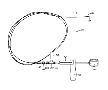
BRIEF DESCRIPTION OF THE DRAWINGS
[0011] FIG. 1 is a partial side view of a distal end of an embodiment of a
delivery device at a tissue treatment site;
- 3a -
CA 02789671 2012-08-10
WO 2011/103245
PCT/US2011/025169
[0012] FIG. 2 is a partial side view of an embodiment of a delivery
device in accordance with the present invention;
[0013] FIG. 3 is a partial side view of the embodiment shown in FIG. 2 in
a first position;
[0014] FIG. 4 is a partial side view of the embodiment shown in FIG. 2 in
a second position;
[0015] FIG. 5 is a side view of a proximal portion an embodiment of a
the delivery device in accordance with the present in;
[0016] FIG. 6 is a side view of the embodiment of the delivery device
shown in FIG. 5;
[0017] FIG. 7 illustrate an embodiment of a delivery device in
accordance with an embodiment of the present invention;
[0018] FIGS. 8A and 8B are side views of adaptors and a tube of the
delivery device shown in FIG. 7;
[0019] FIG. 9 illustrates an embodiment of a kit in accordance with the
present invention;
[0020] FIG. 10 illustrates an embodiment of a kit in accordance with the
present invention;
[0021] FIGS. 11A and 11B illustrate an alternative embodiment of a kit
in accordance with the present invention; and
[0022] FIG. 12 illustrates an injectable solution being delivered to a
treatment side with a delivery device in accordance with the present
invention.
DETAILED DESCRIPTION OF THE EMBODIMENTS
[0023] The invention is described with reference to the drawings in
which like elements are referred to by like numerals. The relationship and
functioning of the various elements of this invention are better understood
by the following detailed description. However, the embodiments of this
invention are not limited to the embodiments illustrated in the drawings. It
should be understood that the drawings are not to scale, and in certain
instances details have been omitted which are not necessary for an
- 4 -
CA 02789671 2012-08-10
WO 2011/103245
PCT/US2011/025169
understanding of the present invention, such as conventional fabrication
and assembly.
[0024] As used in the specification, the terms proximal and distal should
be understood as being in the terms of a physician delivering the injectable
solution to a patient. Hence the term "distal" means the portion of the
device that is farthest from the physician and the term "proximal" means
the portion of the device that is nearest to the physician.
[0025] FIGS. 1 and 2 illustrate a delivery device 100 for delivering an
injectable solution to a tissue treatment site 110. A distal portion 112 of
the delivery device 100 is shown in FIG. 1 including an inner shaft 114
extending out of an outer catheter 116 so that the inner shaft 114 extends
into the tissue 110. The inner shaft 114 may be a needle, cannula or other
elongate tubular structure suitable for insertion into the tissue 110. The
inner shaft 114 is inserted between a first layer of tissue 120 and a second
layer of tissue 122. The layers 120, 122 may be any adjacent layers of
tissue, for example, the muscularis and submucosal layers. As shown in
FIG. 1, the injection of the solution between the first layer 120 and the
second layer 122 forms a fluid-filled pocket 124 that forces separation
between the first and second layers 120, 122, breaking the attachments
between the tissue layers 120, 122. The elevated tissue portion 126 may
then be resected by the physician using an electrocautery device or snare
as described in more detail below.
[0026] A proximal portion 130 of the delivery device 100 is shown in
FIG. 2. The proximal portion 130 includes a housing 134 having a
chamber 136 formed therein. The device 100 further includes an injector
handle 138 connected to the housing 134, a plunger 142 positioned within
the housing 134, a plunger advancer member 143 and a plunger handle
144 operably connected to the plunger advancer member 143. The
plunger advancer member 143 may be connected to the plunger 142 when
the solution is ready to be delivered to the treatment site. A connector 146
is connected to a distal end portion 148 of the housing 134. The connector
- 5 -
CA 02789671 2012-08-10
WO 2011/103245
PCT/US2011/025169
146 removably connects the inner shaft 114 and the outer catheter 116 to
the distal end portion 148 of the housing 134.
[0027] The plunger advancer member143 is insertable into a proximal
opening 152 of the housing 134 and fits on a portion of the plunger 142.
The plunger 142 is advanceable toward the distal end portion 148 of the
housing 134 to decrease the volume of the chamber 136 and advance the
injectable solution into the tissue 110. In some embodiments, the plunger
advancer member 143 is a screw-gear plunger having the plunger handle
144 at a proximal end 156 of the delivery device 100 and a distal end 158
received by the plunger 142 within the chamber 136 of the housing 134.
The screw gear plunger member may include male or female threads or
grooves that may be used to distally advance the plunger 142 to create
pressure within the chamber 136 to force the injectable solution distally
into the tissue 110. In some embodiment the plunger 142 may form a seal
at the proximal end 156 so that the solution does not escape the proximal
end 156. A seal (not shown) may be provided at the distal end 158 of the
plunger 142 that seals the chamber 136 as the plunger 142 is distally
advanced and prevents the injectable solution from flowing proximally past
the plunger 142. The seal allows high pressure within the chamber 134 to
distally advance the injectable solution through the inner shaft 114 without
leaking. By way of non-limiting example, the seal may be an o-ring. In
some embodiments, the seal may be provided in the form of a
polytetrafluoroethylene (PTFE) tape. The PTFE tape may be wound
around the end of the plunger 142 to form the seal between the plunger
142 and the housing wall 134. A distal seal may also be provided on the
distal end of the housing 134 to seal the housing 134 for delivery and
before the housing 134 is connected to a pressure gauge or a connector
as discussed below.
[0028] The housing 134 may be adapted for withstanding positive
displacement pressures associated with advancing injectable solutions
having increased viscosity through the distal end 148 of the housing 134
and into the inner shaft 114. For example, the viscosity of the solution
- 6 -
CA 02789671 2012-08-10
WO 2011/103245
PCT/US2011/025169
within the chamber 136 may be greater than about 10,000 cP. The
housing 134 may be formed from any suitable material sufficient to
withstand the pressure generated for a solution having a viscosity greater
than about 10,000 cP. In some embodiments, the housing may
accommodate a solution having a viscosity greater than about 30,000 cP.
Materials for forming the housing may include, but are not limited to plastic,
such as polycarbonate, and glass.
[0029] In some embodiments, the delivery device 100 includes a
pressure gauge 175 as shown in FIG. 5. The pressure gauge is operably
connected to the distal end 148 of the housing 134, for example, using a y-
adaptor 177 having a connector 179 for connecting to the connector 146
that removably connects the inner shaft 114 and the outer catheter 116.
The y-adaptor 177 may be glued to the connector 179 and to a connector
181 that connects to the distal end 148 of the housing 134 so that the high
pressure solution does not leak from the connections. FIG. 6 illustrates the
pressure gauge 175 operably connected to the housing 134 and the
connector 146 connected to the outer catheter 116. The solution may be
delivered through the inner shaft at a nominal pressure between about 1
psi to about 3000 psi. The delivery device 100 may also include an
automatic stop that prevents the physician from exceeding a
predetermined pressure, for example, if the inner catheter 114 becomes
clogged or bent. One stop may be provided when the pressure exceeds
about 2000 psi. In some embodiments, a stop may be provided with the
pressure exceeds about 3000 psi. Other pressure cut offs may also be
used. The amount of pressure measured will vary depending on the
concentration of the solution being delivered.
[0030] As shown in FIGS. 2 and 6, the device 100 includes the injector
handle 138 for gripping by the operator. The injector handle 138 supports
the housing 134 at a proximal end 160 of the housing 134. The injector
handle 138 may include a cutout 162 sized and shaped to receive the
proximal end 160 of the housing 134. For example, the cutout 162 may be
configured to receive a flared end, such as the end of a syringe. The
- 7 -
CA 02789671 2012-08-10
WO 2011/103245
PCT/US2011/025169
injector handle 138 further includes an opening 168 that is aligned with the
proximal opening 152 of the housing 134 so that the plunger advancer
member 143 may be received through the openings 168 and 152 and be
connected to the plunger 142 inserted into the chamber 136 of the housing
134. The injector handle 138 may be held in one hand by the operator
while the other hand rotates the plunger handle 144 to distally advance the
plunger member 143. Depending on the type of threads or grooves
present on the plunger member 143, the plunger handle 144 may be
turned clockwise or counter-clockwise to distally advance the plunger
member 143 and the plunger 142.
[0031] As shown in FIG. 3, the housing 134 also includes an outlet 172
at the distal end portion 148 of the housing 134 for delivering the injectable
solution from the chamber 136 to the inner shaft 114. The outlet 172 may
include a Luer fitting 174 for connecting with the connector 146 connected
to a proximal end 176 of the inner shaft 114. An additional connector 180
may be provided on the outer catheter 116 for removably connecting with
the connector 146. The connector 180 may also be tightened against the
inner shaft 114 to hold the outer catheter 116 in position relative to the
inner shaft 114. As shown in FIG. 3, a distal end 184 of the outer catheter
116 may be positioned to cover a distal end 186 the inner shaft 114, for
example during delivery to the tissue treatment site 110. (Compare with
FIG. 4.)
[0032] The connector 180 may also be released so that the outer
catheter 116 is movably positionable relative to the inner shaft 114 to
expose a distal end 186 of the inner shaft 114 as shown in FIG. 4. The
connector 180 may be connected to the connector 146 and the distal end
186 of the inner shaft 114 distally extended from the outer catheter 116 to
a maximum length. The outer catheter 116 is movably positionable so that
any length of the distal end 186 of the inner shaft 114 may be exposed
between a maximum length and no exposure. By way of non-limiting
example, 0-15 mm of the distal end 186 of the inner shaft 114 may be
distally extended from the outer catheter 116. Preferably, 7-12 mm of the
- 8 -
CA 02789671 2012-08-10
WO 2011/103245
PCT/US2011/025169
distal end 186 of the inner shaft may be distally extended from the outer
catheter 116. The length of the distal end 186 of the inner shaft exposed
will depend on the depth of the tissue to be penetrated. The distal end of
the inner shaft 114 may be pointed, beveled, blunt or any shape suitable
for insertion of the distal end 186 through the tissue layer 120. In some
embodiments, the inner shaft 114 may provided as a needle, such as a 19,
21, 22, 23 or 25 gauge needle, although any size inner shaft 114 may be
used. In some embodiments, the inner shaft 114 and outer catheter 116
may be delivered to the tissue treatment site 110 through the working
channel of an endoscope and the size of the inner shaft 114 and the outer
catheter 116 will depend on the size of the working channel. For example,
the inner shaft 114 may be provided as a 19 gauge needle that is
extendable through the working channel of an endoscope as shown in
FIGS. 3, 4 and 12. The inner shaft 114 includes a uniform inner diameter
from the proximal end 176 to the distal end 186. The inner shaft 114
having a gauge of 19 or greater allows for easier navigation through a
lumen and provides a uniform conduit for the viscous fluid.
[0033] An embodiment of the delivery device 100 is shown in FIG. 7
including a t-shaped fitting 202 connecting the pressure gauge 175 to the
housing 134 and the connector 146 of the inner shaft 114. A first adaptor
204 is connected to the connector 146 and a second adaptor 206 is
connected to the housing 134. As shown in FIGS. 8A and 8B, the second
adaptor 206 may be a female Luer lock adaptor and the first adaptor 204
may be a male Luer lock adaptor. As shown in FIGS. 8A and 8B, a tube
208 may be provided that extends between the adaptors 204, 206. The
tube 208 extends within the t-shaped fitting 202 and facilitates reduction of
lost solution volume within the fitting 202 as the pressure of the solution is
measured by the gauge 175. An opening 210 is provided in the tube 208
to allow the solution to reach the gauge 175. In some embodiments, the
fitting 202 may be formed from stainless steel or any suitable material able
to withstand the pressure flowing through the fitting 202. The adaptors
- 9 -
CA 02789671 2012-08-10
WO 2011/103245
PCT/US2011/025169
204, 206 and the tube 208 may be formed from nylon or any suitable
material able to withstand the pressure flowing therethrough.
[0034] The delivery device 100 may be provided in a kit 200 as shown in
FIG. 9. In this embodiment, the kit 200 includes the housing 134, the
injector handle 138, the plunger 142, the plunger advancer member 143,
the plunger handle 144 and the inner shaft 114 and outer catheter 116.
The inner shaft 114 is positioned within the outer catheter 116 and secured
by the connector 180 so that the distal end 186 of the inner shaft 114 is
completely covered by the outer catheter 116. The plunger advancer
member 143 and plunger handle 144 may be provided connected together
and separate from the housing 134 and the plunger 142. The injector
handle 138 may be provided within the kit pre-connected to the housing
134. The housing 134 may be pre-filled with the injectable solution
premixed and ready to be injected directly from the housing 134. The
opening 168 in the injector handle 138 and/or the opening 152 in the
housing 134 may be protected with a removable seal, a frangible seal or
the plunger 142 alone or the like so that the injectable solution remains
sterile and contained within the housing 134. The distal end 148 may be
provided with a cap 186 to secure closure of the distal end 148 to maintain
the sterility and containment of the injectable solution. The components of
the kit 200 may be secured to a support member 188 using a plurality of
tabs 190 to hold each of the components to the support member 88. The
kit 200 may be enclosed within an outer package 202 and the outer
package 202 may provide a sterile enclosure for the kit 200.
[0035] In some embodiments, a kit 202 may also be provided with a
plurality of housings 134 as shown in FIG. 10. The plurality of housings
134 may include different concentrations of the injectable solution or each
housing 134 having the same concentration, for example, for treatment of
multiple tissue lesions in the same patient or treatment of a single large
lesion. The volume of the injectable solution provided in housing 134 of
the kit 202 may be any volume suitable for a patient treatment. By way of
non-limiting example, the suitable volume provided in the housing 134 may
- 10 -
CA 02789671 2012-08-10
WO 2011/103245
PCT/US2011/025169
be about 1cc to 50cc. However, greater or smaller volumes may be
provided depending on the size of the lesion(s) and the number of
treatments being provided.
[0036] As shown in FIG. 10, the kit 202 may be provided with the
housing(s) 134 provided separately and prefilled with the injectable
solution. Both ends of the housing 134 are sealed to maintain sterility of
the injectable solution within the kit 202. The pressure gauge 175 may be
provided connected to the connectors 146, 180 and the inner shaft 114
and the outer catheter 116. The handle 138 may be provided separately.
The plunger advancer member 143 and plunger handle 144 may be
connected together and provided separate from the other components of
the kit 202.
[0037] As shown in FIGS. 11A and 11B, a kit 300 may be provided with
the housing 134 prefilled with the injectable solution provided within the
chamber 136 may be packaged separately from the other components.
The pressure gauge 175 when included with the delivery system 100 may
also be provided operably connected to the housing 134. The separately
packaged housing 134 and the solution therein may be sterilized, for
example, using gamma irradiation, and packaged in a package 204. The
plunger 142 may provide the seal at the proximal end of the chamber 136
or an additional seal as described above may be included. The distal end
148 may be provided with a cap 186 to secure closure of the distal end
148 to maintain the sterility and containment of the injectable solution. As
shown in FIG. 8B, the handle 138, the plunger member 143 connected to
the plunger handle 144 and the inner shaft 114 is positioned within the
outer catheter and secured by the connector 180 so that the distal end 186
of the inner shaft 114 is completely covered by the outer catheter 116 may
be provided in a second package 206. The two packages 204 and 206
may be provided together in the kit 300. Alternatively, the kit 300 may
include the first package 204 and the other components provided
separately.
- 11 -
CA 02789671 2012-08-10
WO 2011/103245
PCT/US2011/025169
[0038] An injectable solution suitable for use with the delivery device
100 and suitable for being provided within the housing 134 of the kit 200 is
described below. The injectable solution is a pharmaceutically acceptable
solution for use in humans and animals that has minimal tissue reactivity.
In some embodiments, the injectable solution has a viscosity greater than
about 10,000 cP, and in some embodiments, a viscosity greater than about
30,000 cP and greater than about 50,000 cP. The preferred viscosity for
the injectable solution is between about 10,000 to 150,000 cP, and in
some embodiment the preferred viscosity for the injectable solution is
between about 30,000 cP and about 120,0000 cP, although other
viscosities may be used. The viscosity of the injectable solution preferably
should be high enough to separate the tissue layers. Non-limiting
examples of suitable materials for inclusion in the injectable solution
include methylcelluloses, such as carboxymethyl cellulose (CMC) and
hydroxyypropyl methylcellulose (HPMC), extracellullar matrix proteins,
elastin, collagen, gelatin, fibrin, agarose, and alginate or mixtures thereof.
The injectable solution with be described with reference to CMC although
one skilled in the art will understand that other suitable materials may also
be used to form the injectable solution.
[0039] Suitable concentrations of the CMC for the injectable solution
include about 1% to 10% CMC (e.g. about 1%, 1,5, 2%, 2.5%,3%, 3.5%,
4%, 4.5%, 5%, 5.5%, 6%, 6.5%, 7%, 7.5%, 8%, 8.5%, 9%, 9.5%, or 10%).
Preferably CMC concentrations range from about 2.5% to 3.5%, and more
preferably about 3%. The CMC may be mixed with sterile water, saline or
other pharmaceutically acceptable solution to provide a suitable
concentration for injection. (CMC may be purchased from Sigma Aldrich,
St. Louis, MO.) The injectable solution may also include additional
components, including, but not limited to dyes, such as food coloring,
methylene blue or carbon black, and hemostasis regulators, such as
vasoconstrictors, for example, epinephrine.
[0040] In operation, the CMC is premixed with a pharmaceutically
acceptable solution at the manufacturer to the desired concentration for
- 12 -
CA 02789671 2012-08-10
WO 2011/103245
PCT/US2011/025169
the injectable solution. The CMC injectable solution is loaded into the
housing 134 at the manufacturer and the housing 134 is sealed under
sterile conditions to maintain the sterility of the CMC injectable solution
for
delivery to the patient. The remaining components of the kit 200 are
assembled together on the support member 88 and packaged for delivery
to the physician.
[0041] The ESD procedure is described herein with reference to
removal of a gastric lesion as shown in FIG. 12, however, the procedure
may be performed anywhere in the body having lesions formed in a layer
of tissue. The physician may access the tissue treatment site using an
endoscope 20 having a visualization port for advancement through a bodily
lumen to the site using a wire guide. The distal portion 112 of the delivery
device 100 may be advanced to the tissue treatment site 110 through a
working channel 22 of the endoscope 20. The distal end 186 of the inner
shaft 114 is covered by the outer catheter 116 during advancement to the
tissue site 110. The distal end 186 of the inner shaft 114 is extended distal
to the outer catheter 116 and advanced into the first layer of tissue 120 at
the treatment site 110. The length of the distal end of the inner shaft 114
is extended will depend on several factors, including, but not limited to, the
size of the lesion and the depth of the tissue wall that is to be elevated by
the injectable solution. The depth and extension of the inner shaft 114 will
be determined and monitored by the physician. In some embodiments, the
distal end 186 of the inner shaft 114 may be extended about 5-15 mm
beyond the outer catheter.
[0042] The physician can monitor the depth of the injection required
using the visualization port of the endoscope. An injection of saline or
other pharmaceutically acceptable solution may be used to initiate the
formation of the tissue pocket 126. The CMC injectable solution is injected
into the same injection site through the inner catheter 114 in an amount
sufficient to create the tissue pocket 126 for a time sufficient for the
procedure. The CMC injectable solution is injected under sufficient
pressure and with a sufficient volume and viscosity to break the cellular
-13-
CA 02789671 2012-08-10
WO 2011/103245
PCT/US2011/025169
attachments between the first layer 120 and the second layer 122 at the
tissue treatment site 110. A dye may be included with the CMC injectable
solution to help the physician visualize the elevated portion of the tissue.
The amount of CMC injectable solution injected to form the tissue pocket
126 is determined by the physician. Once the tissue pocket is formed, the
inner shaft 114 is removed and an electrocautery device or snare is
inserted into the working channel and advanced distally to the treatment
site 110 and the diseased tissue removed.
[0043] The above Figures and disclosure are intended to be illustrative
and not exhaustive. This description will suggest many variations and
alternatives to one of ordinary skill in the art. All such variations and
alternatives are intended to be encompassed within the scope of the
attached claims. Those familiar with the art may recognize other
equivalents to the specific embodiments described herein which
equivalents are also intended to be encompassed by the attached claims.
- 14 -