Note: Descriptions are shown in the official language in which they were submitted.
CA 02789702 2017-02-21
FIBER OPTIC DISTRIBUTION NETWORK FOR MULTIPLE DWELLING UNITS
BACKGROUND
[0001] Field of the Disclosure
[0002] The technology of the disclosure relates to a fiber optic
distribution network
for indoor applications, particularly for a multiple dwelling unit. The fiber
optic network can
include a riser cable having tap or connection points for extending the fiber
optic network to
multiple floors of a multiple dwelling unit.
Technical Background
[0003] In the world of the ever-increasing need for broadband bandwidth
optical
cables have become the main part of telecommunication networks. Optical cables
can
transmit voice signals, data signals and video signals for very long distances
with very high
speed. Developments of optic telecommunication networks allow the connection
of the end
user directly to the optical fiber. This kind of network technology known as
FTTH
technology (fiber to the home) requires extending an "all optical"
communication network
closer to the subscribers. As a result such telecommunication networks include
large number
distribution points from a distribution cable to an end user or subscriber.
[0004] One of the key parts of the FTTH network is the last mile connection
which
often is an indoor installation. Different kind of buildings like multi
dwelling units and block
of apartment require complicated cabling systems which might mean that there
are many
1
CA 02789702 2012-08-13
WO 2011/116081 PCT/US2011/028650
separated cables, each one to connect one subscriber. Installation of many
cables which
provide the connection between a main distribution point (which usually is
located in the
basement or in another place of the building) and the end user may cause many
problems
with routing through the wall or levels of the building. As a result, such
installations consume
a lot of time and costs.
SUMMARY OF THE DETAILED DESCRIPTION
[0005] Embodiments disclosed in the detailed description include a fiber
optic
network for a multiple dwelling unit (MDU) comprising a riser cable
preconnectorized with a
first riser optical connector. The riser cable is optically connected to a
feeder cable providing
optical communication service to the MDU. The riser cable has one or more
preset mid-span
access points along the length of the riser cable. One or more optical fibers
of the riser cable
extend from the riser cable at the one or more preset mid-span access points
and are
preconnectorized with a second riser optical connector. A first adapter is
located at a lower
level of the MDU. The first adapter has a first end and a second end and
configured to
receive the first riser optical connector at the first end of the first
adapter. A second adapter
is located at one of the one or more distribution levels. The second adapter
has a first end and
a second end. A payout reel is adapted to pay out the riser cable such that
the riser cable
extends between the lower level and at least one of the one or more
distribution levels. The
second adapter is configured to receive the second riser optical connector at
the first end of
the second adapter and to optically connect a drop cable via the second end of
the second
adapter to establish optical connection between the feeder cable, the riser
cable and the drop
cable. The payout reel is adapted to store a length of the riser cable when
the first riser
optical connector is received by the first adapter and the second riser
optical connector is
received by the second adapter.
[0006] In another embodiment, a fiber optic network for a multiple
dwelling unit
(MDU) comprising a riser cable having a first riser multi-fiber connector at
one end and a
second riser multi-fiber connector at the other end is disclosed. The riser
cable is optically
connected to a feeder cable providing optical communication service to the
MDU. A first
2
CA 02789702 2012-08-13
WO 2011/116081 PCT/US2011/028650
multi-fiber adapter is located at a lower level of the MDU. The first multi-
fiber adapter has a
first end and a second end. The first multi-fiber adapter is configured to
receive the first riser
multi-fiber connector at the first end of the first multi-fiber adapter. A
second multi-fiber
adapter is located at one of the one or more distribution levels. The second
multi-fiber adapter
has a first end and a second end. A payout reel is adapted to payout the riser
cable such that
the riser cable extends between the lower level and at least one of the one or
more
distribution levels. The second multi-fiber adapter is configured to receive
the second riser
multi-fiber connector at the first end of the second multi-fiber adapter and
to optically
connect a drop cable via the second end of the second multi-fiber adapter to
establish optical
connection between the feeder cable, the riser cable and the drop cable. The
payout reel is
adapted to store a length of the riser cable when the first riser multi-fiber
connector is
received by the first multi-fiber adapter and the second riser multi-fiber
connector is received
by the second multi-fiber adapter.
[0007] In another embodiment, a method for installing a riser cable in a
multiple
dwelling unit (MDU) is disclosed. The method comprising positioning a payout
reel with a
riser cable in the MDU; providing a leader having an extending feature for
paying out the the
riser cable from the payout reel; attaching the extending feature to the riser
cable; and
extending the leader to one or more distribution levels of the MDU. By
extending the leader
the riser cable pays out from the payout reel in manner to align with each of
the one or more
distribution levels to enable an optical connection between an optical fiber
in the riser cable
and an optical fiber in a drop cable at one of the one or more distribution
levels.
BRIEF DESCRIPTION OF THE FIGURES
[0008] FIG. 1 is a schematic diagram of a perspective elevation view of a
multiple
dwelling unit (MDU) with an exemplary fiber optic network installed therein,
wherein a riser
cable with pre-set tap points extends from a payout reel in a patch panel
enclosure located at
a lower level to multiple distribution levels;
3
CA 02789702 2012-08-13
WO 2011/116081 PCT/US2011/028650
[0009] FIG. 2 is a schematic diagram of a perspective elevation view of a
MDU with
an exemplary fiber optic network installed therein, wherein a riser cable with
pre-set tap
points extends from a payout reel in a slack enclosure on a distribution level
to other
distribution levels and to a lower level;
[0010] FIG. 3 is a schematic diagram of a perspective elevation view of a
MDU with
an exemplary fiber optic network installed therein, wherein a riser cable with
pre-set tap
points extends from a payout reel in a FDT on a distribution level to other
distribution levels
and the lower level;
[0011] FIG. 4 is a schematic diagram of a perspective elevation view of a
MDU with
an exemplary fiber optic network installed therein, wherein a plurality of
riser cables each
extend from a separate payout reel in a patch panel enclosure located at the
lower level to one
of the distribution levels;
[0012] FIG. 5 is a schematic diagram of a perspective elevation view of a
MDU with
an exemplary fiber optic network installed therein, wherein a plurality of
riser cables each
extend from a separate FDTs each located at one of the distribution levels to
the patch panel
enclosure located at the lower level;
[0013] FIG. 6 is a schematic diagram of a bundled drop cable extending
from a FDT
to a subscriber premises located on a distribution level of the MDU;
[0014] FIG. 7 is a schematic diagram of an elevation view of an exemplary
preconnectorized riser cable installation assembly with a plurality of
preconnectorized riser
cables being extended from payout reels located at a lower level by a leader
with extending
features attached to the leader at preset locations;
[0015] FIG. 7A is a detail view of an exemplary pull device assembly
which may be
attached to the end of the riser cable to facilitate extending the riser cable
from the payout
reel;
[0016] FIG. 8 is a flowchart illustrating a method of installing a
plurality of
preconnectoized riser cables from payout reels located at a lower level to
FDTs located at
distribution levels, according to an exemplary embodiment;
4
CA 02789702 2012-08-13
WO 2011/116081 PCT/US2011/028650
[0017] FIG. 9 is a schematic diagram of an elevation view of an exemplary
preconnectorized riser cable installation assembly with a plurality of
preconnectorized risers
being extended from payout reels located at distribution levels by a leader
with extending
features attached to the leader at preset locations;
[0018] FIG. 10 is a flowchart illustrating a method of installing a
plurality of
preconnectoized riser cables from payout reels located at distribution levels
to a patch panel
enclosure located at the lower level, according to an exemplary embodiment;
[0019] FIG. 11 is a schematic diagram of a front, perspective view of an
exemplary
local convergence point (LCP) for use with a fiber optic network in a MDU;
[0020] FIG. 11A is a schematic diagram of a front, perspective exploded
view of the
LCP of FIG. 11 having an interior panel removably mountable in the LCP,
wherein the
interior panel is configured to support optical fiber in a first section of
the LCP;
[0021] FIG. 11B is a schematic diagram of a front, perspective exploded
view of the
LCP of FIG. 11 having an interior panel removably mountable in the LCP,
wherein the
interior panel is configured to support optical fiber splitting in the second
section of the LCP;
[0022] FIG. 11C is a schematic diagram of a front, perspective exploded
view of the
LCP of FIG. 11 having an interior panel removably mountable in the LCP,
wherein the
interior panel is configured to support optical fiber splicing in the second
section of the LCP;
[0023] FIG. 12 is a schematic diagram of front, elevation views of an
exemplary
patch panel enclosure with a multi-fiber adapter assembly and multiple payout
reels
removably mounted therein;
[0024] FIG. 13 is a schematic diagram of a front, perspective view of an
exemplary
FDT having a module with multi-fiber adapters and single fiber adapters and a
payout reel
removably mounted therein, wherein the FDT is configured to be mounted in-line
with and
supported by the conduit carrying the riser cable;
[0025] FIG. 14 is a schematic diagram of a front, perspective view of an
exemplary
FDT having a module assembly with multi-fiber adapters and single fiber
adapters pivotably
mounted therein and a payout reel removably mounted therein, wherein the FDT
is
configured to be wall or closet mounted; and
CA 02789702 2012-08-13
WO 2011/116081 PCT/US2011/028650
[0026]
FIG. 15 is a schematic diagram of the front, elevation perspective view of the
FDT of FIG. 14 with the module assembly pivoted to an open position.
DESCRIPTION OF THE DISCLOSURE
[0027]
Embodiments disclosed in the detailed description include a fiber optic
distribution network for a multi-floor multiple dwelling unit (MDU). The
network includes a
local convergence point (LCP) which may be located in a lower level of the
MDU, for
example, the basement. The
LCP receives a feeder cable that provides optical
communication service to the MDU from a service provider. One or more
preconnectorized
riser cables having multi-fiber connectors on each end optically connect to
the feeder cable
through the LCP. The riser cable extends from the LCP to one or more upper
distribution
levels of the MDU. At the distribution level, the riser cable is received by a
network access
point, which may be comprisd of a fiber distribution terminal (FDT), a mid-
span access point,
or the like. For purposes herein, the terms network access point may be used
to describe
either one or more of the FDT and the mid-span access point. Additionally, it
should be
understood that the terms FDT, pipe-in-box, and closet box will be used to
refer and describe
a component of the fiber optic distribution network located at the
distribution level for
optically connecting the riser cable to the drop cable. The term patch panel
enclosure will be
used when describing the component of the fiber optic distribution network for
optically
connecting and extending the riser cable to the LCP and, thereby, to the
feeder cable.
[0028]
Optically connecting the riser cable and to the subscriber premises may be
through tether cables branched off from the riser cable at each distribution
level, for example,
at a mid-span access point of the riser cable. The tether cables may be
connected to
subscriber premises via one or more drop cables at the network access point.
Alternatively,
or additionally, an individual riser cable may be extended to the distribution
level and
optically connect to one or more drop cables routed to the subscriber
premises. In such case,
a tether cable may not be branched off of the riser cable at a mid-span access
point. The drop
cable extends to the subscriber premises at the distribution level to provide
optical
communication service to the subscriber. Any riser cable slack may be stored
in the FDT, the
6
CA 02789702 2012-08-13
WO 2011/116081 PCT/US2011/028650
patch panel enclosure, and/or a separate slack enclosure. Additionally, the
riser cable slack
may be stored on the payout reel, with the payout reel removably mounted in
the FDT, the
patch panel enclosure, or the slack enclosure. The slack enclosure may be
located at or
adjacent to the LCP or at one or more of the distribution levels.
[0029] The end of the riser cable would optically connect to the end of
one or more
drop cables. In either case, the tether cable and/or the riser cable may
terminate in a fiber
optic connector and optically connect to the drop cable terminated in a fiber
optic connector
through a suitable fiber optic adapter. The fiber optic adapter may be one
that provides for
multi-fiber connector to multi-fiber connector interconnection, such as, for
example an MTP
adapter, or other types of multi-fiber adapters. Additionally or
alternatively, the fiber optic
adapter may be one that provides for single fiber connector to single fiber
connector
interconnection, for example an SC adapter, or other types of single fiber
adapters. The fiber
optic adapters may have dual shutters, one on each end of the adapter. The
shutters are
adapted to automatically close against the end of the adapter when a fiber
optic connector is
not inserted in that end of the adapter. In this manner, the shutters may
provide sealing of the
adapter against the environment, keeping the adapter protected and clean when
not in use.
The adapter may be keyed up and down to coordinate with the polarity of the
connectors.
The adapters may be mounted in a cassette or module which is removably mounted
in the
network access point. Alternatively, the adapter may be removably mounted to a
panel which
may be removably mounted in the network access point.
[0030] As such, the FDT and/or the patch panel enclosure may act as or be
a
transition box having one or more removably mounted fiber optic adapters
configured to
receive one or more optical fibers of a riser cable to provide optical
communication service
from a service provider to a subscriber premises. Additionally, the transition
box may have
one or more removably mounted payout reels storing the slack of the riser
cable or cables
paid out in the MDU.
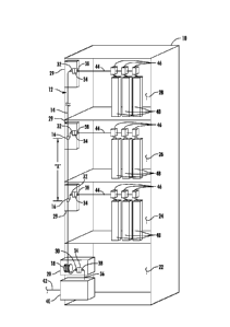
[0031] In this regard, FIGS. 1-6 illustrate exemplary embodiments of
fiber optic
networks in an MDU 10. FIGS. 1-5 are schematic diagrams of a perspective
elevation views
of the MDU 10 with an exemplary fiber optic networks 12, 112, 212, 312, 412
installed
7
CA 02789702 2012-08-13
WO 2011/116081 PCT/US2011/028650
therein, extending to distribution levels in the MDU 10. FIG. 6 is a schematic
diagram of a
bundled drop extending to a subscriber premises at a distribution level of the
MDU 10. A
distribution level may be designated for one of the floors of the MDU 10, or
may be
designated for any combination of a number of floors of the MDU 10, or for any
portion of a
floor of the MDU 10. In FIGS. 1-5, one or more of the riser cables 14 are
shown connecting
to a local convergence point (LCP) 40 through a patch panel enclosure 20.
Alternatively, and
although not shown in FIGS. 1-5, the one or more riser cables 14 may connect
directly to the
LCP 40 without the patch panel enclosure 20.
[0032] Referring now to FIG. 1, a riser cable 14 with pre-set mid-span
access points
16 extends from a payout reel 18. The mid-span access point 16 may comprise a
FlexNAP
System, as commercially available from Corning Cable Systems LLC, or other
type of
connection or system that provides for the separation of one or more optical
fibers from the
riser cable 14. The riser cable 14 pays out from a payout reel 18. Once the
riser cable 14 is
paid out from the payout reel 18 to multiple distribution levels 24, 26, 28,
the payout reel 18
is removably mounted in a patch panel enclosure 20. Although, in FIG. 1 three
higher levels
24, 26, 28 are illustrated, the fiber optic network 12 may have any number of
distribution
levels. The riser cable 14 is preconnectorized with multi-fiber connectors 30,
32 at each end
of the riser cable 14. The patch panel enclosure 20 has a multi-fiber-to-multi-
fiber adapter
assembly 34 which receives a first multi-fiber connector 30. A distribution
cable 36
preconnectorized with a multi-fiber connector 38, is received by and connects
to the multi-
fiber adapter assembly 34 in the patch panel enclosure 20 to establish an
optical connection
between the riser cable 14 and the distribution cable 36. The distribution
cable 36 routes to a
local convergence point (LCP) 40. The LCP 40 receives a feeder cable 42 which
provides
optical communication service to the MDU 10 from a service provider.
[0033] During installation, the riser cable 14 pays out from the payout
reel 18 such
that the riser cable 14 extends generally in an upward direction from the
lower level 22 to
each ascending distribution level 24, 26, 28 in succession with distribution
level 28 being the
highest distribution level in the MDU 10. The mid-span access points 16 are
preset such that
they are separated by a distance "X" along the length of the riser cable 14.
The distance "X"
8
CA 02789702 2012-08-13
WO 2011/116081 PCT/US2011/028650
is preset at the factory to a certain value depending on the distance between
adjoining
distribution levels 24, 26. As examples, the distance "X" may be set at any
desired distance,
as non-limiting examples, 10 feet, 12 feet, 14 feet, 15 feet, and the like. In
this manner, as the
riser cable 14 pays out and installed in the MDU 10, the preset mid-span
access points will
align, generally, with each distribution level 24, 26 of the MDU 10. However,
the one
exception to this may be the highest distribution level 28, since the end of
the riser cable 14
would extend to that level and and would not have a mid-span access point. Any
riser cable
14 slack due to the presetting of the distance "X" or otherwise, may be stored
on the payout
reel 18, in the patch panel enclosure 20, the LCP 40, and/or a slack enclosure
(not shown in
FIG. 1). Slack may also be stored loosely at the lower level 22, and/or in one
ore more fiber
distribution terminals 29 located at one or more of the distribution levels
24, 26, 28.
Additionally, the payout reel 18 may be removably mounted in the slack housing
or may be
mounted or located separate from the patch panel enclosure 20 and/or slack
enclosure and/or
from the FDT 29 at one or more of the distribution levels 24, 26, 28.
[0034] The
riser cable 14 may be any number of optical fibers, as non-limiting
examples, 6, 8, 12 or 24 fibers. At each mid-span access point 16, certain of
the optical fibers
may be separated or furcated out from the riser cable 14 in a FDT 29 located
at the
distribution level 24, 26. As non-limiting examples, 6, 8 or 12 fibers may be
furcated out
from the riser cable 14 and terminated with the second multi-fiber connector
32. At the
highest distribution level 28, the optical fibers remaining in the riser cable
14 after furcating
out the optical fibers at lower distribution levels 24, 26 are terminated with
the second multi-
fiber connector 32. The second multi-fiber connector 32 may be received by a
multi-fiber
adapter assembly 34 removably mounted in the FDT 29 at the distribution level
24, 26, 28.
The multi-fiber adapter assembly 34 may be removably mounted in a connector
module or
panel (not shown in FIG. 1), which may be removably mounted in the FDT 29.
[0035] A
multi-fiber bundled drop cable 44 preconnectorized with a multi-fiber
connector 38, is received by and connects to the multi-fiber adapter assembly
34, or the
connector module, as the case may be, in the FDT 29 located at the
distribution reel 24, 26,
28. In this manner an optical connection is established between the riser
cable 14 and the
9
CA 02789702 2012-08-13
WO 2011/116081 PCT/US2011/028650
multi-fiber bundled drop cable 44. The multi-fiber bundled drop cable 44
routes to one or
more drop boxes 46 associated with subscriber premises 48 located at the
distribution level
24, 26, 28. One or more optical fiber separates from the multi-fiber bundled
drop cable 44 at
the drop box 46 and extends to the subscriber premises 48. In this manner,
optical
communication service is provided to the subscriber premises 48.
[0036]
Alternatively or additionally, one or more connectorized harnesses or jumpers
may be connected between the multi-fiber adapters in the multi-fiber adapter
assembly 34
and extended to single fiber adapters (not shown in Fig. 1). In such a case,
connectorized
single fiber drop cables may connect to the harnesses or jumpers to establish
optical
connection with the riser cable 14, and ultimately to the subscriber premises
48.
[0037]
FIG. 2 is a schematic diagram of a perspective elevation view the MDU 10
with an exemplary fiber optic network 112 installed therein. The riser cable
14 with pre-set
mid-span access points 16 extends from a payout reel 18 in a separate slack
enclosure 50
located at the highest distribution level 28 to the other distribution levels
24, 26 and the the
lower level 22. The fiber optic network 112 is similar to fiber optic network
12 shown on
FIG. 1, and, therefore, the aspects and/or components of the fiber optic
network 112
described with respect to FIG. 1 will not be described again with respect to
FIG. 2. In FIG.
2, after the riser cable 14 is paid out, the payout reel 18 is removably
mounted in the slack
enclosure 50 located at the highest level 28 instead of the patch panel
enclosure 20. In this
manner, during installation, the riser cable 14 pays out from the payout reel
18 such that the
riser cable 14 extends generally in a downward direction from the highest
distribution level
28 to each descending distribution level 26, 24 in succession, and to the
patch panel enclosure
20.
[0038] The
patch panel enclosure 20 includes a multi-fiber adapter assembly 34 but
may not include the payout reel 18 since that is located at the highest
distribution level 28 in
fiber optic network 112. However, the multi-fiber adapter assembly 34 in the
patch panel
enclosure 20 receives the first multi-fiber connector 30 and optically
connects it with the
multi-fiber connector 38 of the distribution cable 36 to establish an optical
connection
CA 02789702 2012-08-13
WO 2011/116081 PCT/US2011/028650
between the riser cable 14 and the distribution cable 36 as described above
with respect to
FIG. 1.
[0039] FIG. 3 is a schematic diagram of a perspective elevation view of
the MDU 10
with an exemplary fiber optic network 212 installed therein. The riser cable
14 with pre-set
mid-span access points 16 extends from the payout reel 18 in the FDT 29
located at the
highest distribution level 28 to the other distribution levels 24, 26. The
fiber optic network
212 is similar to fiber optic network 12 shown on FIG. 1 and the fiber optic
network 112
shown on FIG. 2 and, therefore, the aspects and/or components of the fiber
optic network
212 described with respect to FIG. 1 and/or FIG. 2 will not be described again
with respect
to FIG. 3. In FIG. 3, after the riser cable 14 is paid out, the payout reel 18
is removably
mounted in the FDT 29 located at the highest distribution level 28 instead of
the slack
enclosure 50, as described with respect to FIG. 2. In this way, the slack
enclosure 50 is not
needed at the highest distribution level 28 conserving space. The paying out
and installation
of the riser cable 14 may be the same as described with respect to FIG. 2.
[0040] FIG. 4 is a schematic diagram of a perspective elevation view of
the MDU 10
with an exemplary fiber optic network 312 installed therein. A plurality of
riser cables 14(1),
14(2), 14(3) each extend from a separate payout reel 18(1), 18(2), 18(3) in
the patch panel
enclosure 20 and extending to respective ones of the distribution levels 24,
26, 28. Each riser
cable 14(1), 14(2), 14(3) pays out from respective payout reels 18(1), 18(2),
18(3). After the
riser cable 14(1), 14(2), 14(3) is paid out, the respective payout reel 18(1),
18(2), 18(3) is
removably mounted in the patch panel enclosure 20. The riser cables 14(1),
14(2), 14(3)
extend generally in an upward direction from the lower level 22 to separate
ascending
distribution level 24, 26, 28. In this manner, a separate riser cable 14
provides optical service
to a separate distribution level 24, 26, 28. Each of the riser cables 14(1),
14(2), 14(3)
terminates with respective second multi-fiber connectors 32(1), 32(2), 32(3)
which are
received by and connected to the respective multi-fiber adapter assembly 34 in
the FDT 29
located at the distribution levels 24, 26, 28. In the patch panel enclosure
20, the riser cables
14(1), 14(2), 14(3) extend from each of the payout reels 18(1), 18(2), 18(3)
to the multi-fiber
adapter assembly 34 located at the patch panel enclosure 20. The first multi-
fiber connector
11
CA 02789702 2012-08-13
WO 2011/116081 PCT/US2011/028650
30(1), 30(2), 30(3) of each respective riser cable 14(1), 14(2), 14(3) is
received by and
connects to the multi-fiber adapter assembly 34 in the patch panel enclosure
20. The
distribution cable 36 preconnectorized with a multi-fiber connector 38, is
received by and
connects to the multi-fiber adapter assembly 34 in the patch panel enclosure
20 to establish
an optical connection between the riser cables 14(1), 14(2), 14(3) and the
distribution cable
36. The distribution cable 36 routes to the LCP 40.
[0041] FIG. 5 is a schematic diagram of a perspective elevation view of
the MDU 10
with an exemplary fiber optic network 412 installed therein. The plurality of
riser cables
14(1), 14(2), 14(3) each extend from separate, respective FDTs 29 located on
one of the
distribution levels 24, 26, 28 to the patch panel enclosure 20. The fiber
optic network 412 is
similar to fiber optic network 312 shown on FIG. 4, and, therefore, the
aspects and/or
components of the fiber optic network 312 described with respect to FIG. 4
will not be
described again with respect to FIG. 5. Each riser cable 14(1), 14(2), 14(3)
pays out from
respective payout reels 18(1), 18(2), 18(3). After the necessary length of
riser cable 14(1),
14(2), 14(3) is paid out, the payout reel 18(1), 18(2), 18(3) is removably
mounted in separate,
respective FDTS 29 located at respective distribution levels 24, 26, 28. The
riser cables
14(1), 14(2), 14(3) extend generally in a downward direction from the
respective FDTs 29
located at respective distribution levels 24, 26, 28 to the lower level 22. In
this manner, a
separate riser cable 14 provides optical service to a separate distribution
level 24, 26, 28.
Each of the riser cables 14(1), 14(2), 14(3) terminates with respective second
multi-fiber
connectors 32(1), 32(2), 32(3) which are received by and connected to the
respective multi-
fiber adapter assembly 34 in the FDT 29 located at the distribution levels 24,
26, 28. In the
patch panel enclosure 20, the first multi-fiber connector 30(1), 30(2), 30(3)
of each respective
riser cable 14(1), 14(2), 14(3) is received by and connects to the multi-fiber
adapter assembly
34 in the patch panel enclosure 20. The distribution cable 36 preconnectorized
with a multi-
fiber connector 38, is received by and connects to the multi-fiber adapter
assembly 34 in the
patch panel enclosure 20 to establish an optical connection between the riser
cables 14(1),
14(2), 14(3) and the distribution cable 36. The distribution cable 36 routes
to the LCP 40.
12
CA 02789702 2012-08-13
WO 2011/116081 PCT/US2011/028650
[0042] Referring now to FIG. 6, the portion of the fiber optic networks
12, 112, 212,
312, 412 at the distribution level 24, 26, 28 is illustrated. The multi-fiber
bundled drop cable
44 extends from the FDT 29 at the distribution level 24, 26, 28 to drop box 46
associated with
the and located at the subscriber premises 48. The multi-fiber bundled drop
cable 44 includes
multiple fiber optic cables 52 retained together by one or more helically
wrapped external
binders 54. One or more of the multiple fiber optic cables is separated from
the multi-fiber
bundled drop cable 44 by removing the multiple fiber optic cable from the
retainage of the
one or more external binders. The separated fiber optic cable 52 may then
extend to the
subscriber premises 48.
[0043] FIG. 7 is a schematic diagram of an elevation view of an exemplary
preconnectorized riser cable installation assembly 56 with a plurality of
preconnectorized
riser cables 14(1), 14(2), 14(3) being extended from respective payout reels
18(1), 18(2),
18(3) located at a lower level 22 by a leader 58 with extending features 60
attached to the
leader 58 at preset locations at a distance "Y" along the length of the leader
58. The
extending feature 60 may be any type of loop, hook, swivel, or the like,
configured to attach
to the second multi-fiber connectors 32(1), 32(2), 32(3), or to some type of
pull device
attached to the second multi-fiber connectors 32(1), 32(2), 32(3) to provide
for safely and
effectively paying out the riser cables 14(1), 14(2), 14(3).
[0044] FIG. 7A is a detail view of a pull device assembly 62 which may be
attached
to the end of the riser cable 14 to facilitate extending the riser cable 14
from the payout reel
18. The pull device assembly 62 attaches to the riser cable 14 around the
second multi-fiber
connector 32 enclosing the second multi-fiber connector 32, boot and a portion
of the riser
cable 14. The pull device assembly 62 has a swivel end 64 and a body 66. The
body 66 may
enclose and/or support the second multi-fiber connectors 32. The swivel end 64
is allowed to
rotate freely and independently of the body 66 and, therefore, the the second
multi-fiber
connector 32 and the riser cable 14. The swivel end 64 comprises a hole
through which the
extending feature 60 inserts. As the riser cable 14 is pulled through the MDU
10 particularly
in conduit using a pull loop 68 attached to the end of the leader 58, and the
extending feature
60 attached to the swivel end 64, the swivel end 64 it is allowed to
independently rotate from
13
CA 02789702 2012-08-13
WO 2011/116081 PCT/US2011/028650
the rest of the pull device assembly 62. This independent rotation eliminates
twisting of the
riser cable 14 and the the second multi-fiber connector 32. In this manner, as
the leader 58 is
pulled through the MDU 10 particularly in conduit, the leader 58, the
extending feature 60
and the swivel end 64 reduce or may eliminate any induce additional torsional
stresses on the
riser cable 14 and/or the second multi-fiber connector 32.
[0045] Referring again to FIG. 7, the distance "Y" is preset to a certain
value
depending on the distance between adjoining distribution levels 24, 26, 28. As
non-limting
examples, the distance "Y" may be set at 10 feet, 12 feet, 14 feet, 15 feet,
and the like. In this
manner, as the leader 58 is pulled through the MDU 10, riser cables 14(1),
14(2), 14(3) each
pays out to a point that will align, generally, with each respective
distribution level 24, 26,
28 of the MDU 10. Any riser cable 14 slack due to the presetting of the
distance "Y" or
otherwise, may be stored on the respective payout reel 18(1), 18(2), 18(3)
and/or loosely in
an patch panel enclosure 20 and/or a slack enclosure (not shown in FIG. 7).
Additionally,
slack may be stored loosely, on the payout reels 18(1), 18(2), 18(3) and/or
the FDT 29 at one
or more of the distribution levels 24, 26, 28. Each second multi-fiber
connectors 32(1),
32(2), 32(3), may then be connected to the respective multi-fiber adapter
assembly 34
removably mounted in the FDT 29 located at the respective distribution level
24, 26, 28.
Additionally, the first multi-fiber connectors 30(1), 30(2), 30(3) attached to
respective riser
cables 14(1), 14(2), 14(3) may be connected to the respective multi-fiber
adapter assembly 34
removably mounted in the patch panel enclosure 20.
[0046] FIG. 8 is a flowchart illustrating a method of installing a
plurality of
preconnectoized riser cables 14(1), 14(2), 14(3), from payout reels 18(1),
18(2), 18(3) located
at a lower level 22 to FDTs 29 located at upper levels 24, 26, 28 according to
an exemplary
embodiment. The payout reels 14(1), 14(2), 14(3) are positioned in the lower
level 22 (Step
1000). Optionally, a pull device assembly 62 may be attached to the end of
each riser cable
14(1), 14(2), 14(3) (Step 1002). A leader 58 with extending features 60
located at the pre-set
distance "Y" along the length of the leader 58 is provided (Step 1004). As a
non-limiting
example, the leader may be a 180 pound rated urethane jacketed kevlar. The
extending
features 60 are attached to the end of each riser cable 14(1), 14(2), 14(3),
particularly to each
14
CA 02789702 2012-08-13
WO 2011/116081 PCT/US2011/028650
pull device assembly 62 if such is provided (Step 1006). A pull rope or string
is attached to
the end of the leader 58 through a pull loop 68 (Step 1008) and, using the
pull rope or string,
the leader 58 is pulled to the distribution levels 24, 26, 28 of the MDU 10 in
an ascending
order paying out the riser cables 14(1), 14(2), 14(3) from the respective
payout reels 18(1),
18(2), 18(3) (Step 1010). As a non-limiting example, the pull rope or string
may be a 200
pound rated nylon pull string. A 50 pound pull tension rated plastic mesh
pulling grip may
also be used. At each successive distribution level 24, 26, 28 in the
ascending order, the
leader 58 is accessed and the appropriate riser cable 14(1), 14(2), 14(3) for
that distribution
level 24, 26, 28 is extended. The appropriate riser cable 14(1), 14(2), 14(3)
is disconnected
from the extending feature 60 and the second multi-fiber connector 32(1),
32(2), 32(3) to the
respective multi-fiber adapter assembly 34 in the FDT 29 at the distribution
level 24, 26, 28
(Step 1012). The first multi-fiber connectors 30(1), 30(2), 30(3) may be
conencted to the
multi-fiber adapter assembly 34 located in the patch panel enclosure 20 (Step
1014). Riser
cable 14 slack may be stored in the FDT 29 at the distribution level 24, 26,
28 and/or in the
payout reels 18(1), 18(2),18(3) (Step 1016). The payout reels 18(1),
18(2),18(3) may be
removably mounted in the patch panel enclosure 20.
[0047] Referring again also to FIG. 4, as a non-limiting example, the
extending
features 60 may be positioned further apart than the spacing between
distribution levels 24,
26, 28. If the distribution level is aligned with a floor of the MDU 10, and
the floors are
spaced at 12 feet, the extending feature 60 may be spaced at 14 feet. The
leader 58 and the
riser cable 14(3) is then extended to the upper-most distribution level 28. An
adequate
amount of slack of the riser cable 14(3), for example, 10 feet of slack, is
pulled up and stored
in the FDT 29 at the distribution level 28. The riser cable 14(3) slack is
manually accessed
and extended to the FDT 29 and the second multi-fiber connector 32(3)
connected to the
multi-fiber adapter assembly 34 in the FDT 29. This allows for enough slack of
the riser
cable 14(3) to better facilitate installation. A similar process may then be
used with
successively descending distribution levels 26, 24 of the MDU 10 until the
installation is
complete.
CA 02789702 2012-08-13
WO 2011/116081 PCT/US2011/028650
[0048] FIG. 9 is a schematic diagram of an elevation view of an exemplary
preconnectorized riser cable installation assembly 70 with a plurality of
preconnectorized
riser cables 14(1), 14(2), 14(3) being extended from payout reels 18(1),
18(2),18(3) each
located at respective distribution levels 24, 26, 28 of the MDU 10. The riser
cables 14(1),
14(2), 14(3) by a leader 58 with extending features 60 attached to the leader
58 at preset
locations at a distance "Z" along the length of the leader 58. The extending
feature 60 may
be any type of loop, hook, swivel, or the like, configured to attach to the
second multi-fiber
connectors 32(1), 32(2), 32(3), or to some type of pull device attached to the
second multi-
fiber connectors 32(1), 32(2), 32(3) to provide for safely and effectively
paying out the riser
cables 14(1), 14(2), 14(3). The pull device assembly 66 described with respect
to FIG. 7A,
above, may be attached to the end of the riser cables 14(1), 14(2), 14(3) to
facilitate
extending the riser cables 14(1), 14(2), 14(3) from the payout reels 18(1),
18(2),18(3).
[0049] The distance "Z" is preset to a value, as a nonlimiting example, 6
inches, to
allow the leader 58 to be accessed at each succeeding distribution level 24,
26, 28 in
descending order to attach extending feature 60 to the particular riser cable
14(1), 14(2),
14(3). In other words, the riser cable 14(3) for the highest distribution
level 28 is attached to
the leader first. Then the riser cable 14(2) for then next lower distribution
level 26 is attached
to the leader 58. Then the riser cable 14(1) for the next lower distribution
level 24 is attached
to the leader 58. The leader 58 extends to the lower level 22. Any riser cable
14 slack may
be stored on the respective payout reel 18(1), 18(2), 18(3) and/or loosely in
the FDT 29
and/or a slack enclosure (not shown in FIG. 9) at the distribution level 24,
26, 28.
Additinoally, slack may be stored in the patch panel enclosure 20. Each second
multi-fiber
connectors 32(1), 32(2), 32(3), may then be connected to the respective multi-
fiber adapter
assembly 34 removably mounted in the FDT 29 located at the respective
distribution level 24,
26, 28. Additionally, the first multi-fiber connectors 30(1), 30(2), 30(3)
attached to
respective riser cables 14(1), 14(2), 14(3) may be connected to the respective
multi-fiber
adapter assembly 34 removably mounted in the patch panel enclosure 20.
[0050] FIG. 10 is a flowchart illustrating a method of installing a
plurality of
preconnectoized riser cables 14(1), 14(2), 14(3) from payout reels 18(1),
18(2), 18(3) located
16
CA 02789702 2012-08-13
WO 2011/116081 PCT/US2011/028650
at distribution levels 24, 26, 28 of MDU 10 to the patch panel enclosure 20,
according to an
exemplary embodiment. The payout reels 14(1), 14(2), 14(3) are each positioned
at
respective distribution levels 24, 26, 28 (Step 2000). Optionally, a pull
device assembly 62
may be attached to the end of each riser cable 14(1), 14(2), 14(3) (Step
2002). A leader 58
with extending features 60 located at the pre-set distance "Z" along the
length of the leader
58 is provided (Step 2004). As a non-limiting example, the leader may be a 180
pound rated
urethan jacketed kevlar. A pull rope or string is attached to the pulling loop
68 at the end of
the leader 58 (Step 2006). As a non-limiting example, the pull rope or string
may be a
200pound rated pull string. A 50 pound pull tension rated plastic mesh pulling
grip may also
be used. One of the extending features 60, which may be the first extending
feature 60
closest to the pulling loop 68 is attached to the riser cable 14(3) from the
payout reel 18(3)
located at the highest distribution level 28 in the MDU 10 (Step 2008). The
leader 58 is
extended to the next succeeding distribution level 26, 24 in descending order
(Step 2010). At
the next succeeding distribution level 26, 24, the leader 58 is accessed and
the next extending
feature 60 is attached to the end of that riser cable 14(2), 14(3) (Step
2012). The leader 58 is
extended to all of the distribution levels and the riser cable attached in the
same manner. The
leader 58 is extended to the lower level 22 (Step 2014). The riser cables
14(1), 14(2), 14(3)
are disconnected from the leader 58 and each first multi-fiber connector
30(1), 30(2), 30(3) is
connected to the multi-fiber adapter assembly 34 in the patch panel 20
enclosure (Step 2016).
Each second multi-fiber connector 32(1), 32(2), 32(3) is connected to
respective multi-fiber
adapter assemblies 34 in the FDT 29 located at the distribution levels 24, 26,
28 (Step 2018).
Riser cable 14 slack may be stored in the FDT 29 at the distribution level 24,
26, 28 and/or in
the payout reels 18(1), 18(2),18(3) (Step 2020). The payout reels 18(1),
18(2),18(3) may be
removably mounted in the FDT 29 . Slack may also be stored in the patch panel
enclosure
20.
[0051] FIG. 11 is a schematic diagram of a front, perspective view of an
exemplary
LCP 40 for use with a fiber optic network in a MDU 10. The LCP 40 comprises an
enclosure
72 with a door 74 hingedly attached to the enclosure 72. The door 74 closes to
restrict and/or
prohibit access to the interior 76 of the enclosure 72 and the components
mounted therein,
17
CA 02789702 2012-08-13
WO 2011/116081 PCT/US2011/028650
and opens to allow access to the interior 76 and the components mounted
therein. A
swingable adapter panel 78 mounts in the interior 76. The adapter panel 78 has
a first side
80 (not visible in FIG. 11) and a second side 82 to provide connections of
optical fibers 83
between a feeder side and a distribution side. Pivot points 96 positioned at
the top and
bottom of the interior 76 allow the adapter panel to swing to provide access
to the first side
80 or the second side 82 depending on the positioning of the adapter panel 78.
Additionally,
the adapter panel is lockable in one or more positions. The adapter panel 78
splits the interior
76 into a first section 84 and a second section 86. The LCP 40 is flexible
such that either or
both the first section 84 or the second section 86 can be configured to
support feeder side
optical fiber 83 management and/or connections, and/or distribution side
optical fiber 83
management and/or connections.
[0052] The adapter panel 78 has a connection field 88 that supports multi-
fiber
adapters and connections, single fiber adapters and connections as well as
pass-through
adapters and connection. In FIG. 11, the feeder cable 42 is shown as entering
the LCP 40 at
the bottom into the first section 84 and connecting to splice trays 92. A
continuing section
42(1) of the feeder cable 42 extends from the bottom of the second side 86 to
further provide
optical connection from the service provider to other areas of the MDU 10
and/or to other
MDU's and/or facilities. The distribution cable 36 extends from the top of the
first section
84. The distribution cable 36 optically connects to one or more riser cables
14, which may be
through a multi-fiber adapter assembly 34 in a patch panel housing 20. One or
more splittters
94 may also be mounted in the LCP 40 to split the optical signal carried by
the feeder cable
42 into multiple optical signals for distribution. Fiber routing guides 98 and
fiber
management guides 100 may also be mounted in the first section 84 and/or the
second section
86.
[0053] FIGS. 11A, 11B and 11C are schematic diagrams of front,
perspective,
exploded views of the LCP 40 illustrating interior panels 102(1), 102(2),
102(3) which may
be used in the LCP 40. The interior panels 102(1), 102(2), 102(3) are
intechangeable and
allow the LCP 40 enclosure 72 to be easily reconfigured at the factory or in
the field. This
allows the enclosure 72 to be configured and reconfigured to support multiple
applications
18
CA 02789702 2012-08-13
WO 2011/116081 PCT/US2011/028650
and changing subscriber situations. In this manner, the interior panels
102(1), 102(2), 102(3)
can support, without limitation, fiber splicing, multiple splitter form
factors, cable entries and
other various modifications or arrangements of the LCP 40. Additionally, the
interior panels
102(1), 102(2), 102(3) can be installed on the either the first section 84 or
second section 86
of the interior 76 using any type of fasteners 104, such as, without
limitation, screws, latches
and the like allowing for removable attachment.
[0054] In this regard, FIG. 11A illustrates an interior panel 102(1)
removably
mountable to the enclosure 72 in the interior 76 in the first section 84
configured to support
optical fiber splicing having splice trays 92 and optical fiber management
guides 100. FIG.
11B illustrates an interior panel 102(2) removably mountable to the enclosure
72 in the
interior 76 in the second section 86 configured to support optical fiber
spliting having
splitters 94 and optical fiber management guides 100. FIG. 11C illustrates an
interior panel
102(2) removably mountable to the enclosure 72 in the interior 76 in the
second section 86
configured to support optical fiber splicing having splice trays 92 and
optical fiber
management guides 100. Similarly, although not shown, an interior panel 102
removably
mountable to the enclosure 72 in the interior 76 in the first section 84 may
be configured to
support optical fiber splitting having splitters 94 and optical fiber
management guides 100.
Additionally or alternatively, the interior panels 102 may be configured to
support any type
of function or component, as examples, without limitation, furcation devices,
ribbon fan-out
bodies, wave division multiplexing, coarse wave division multiplexing and
others.
[0055] The LCP 40 provides for a smaller form factor while allow a high
density of
optical fiber connections for distribution of optical service to the MDU 10.
Additionally, the
LCP 40 allows for varrious options for feeder and distribution cables and of
multiple splitters
including, without limitation, at least five 1X32 splitters. The LCP 40 can
also function as a
demarcation point providing 1X1 input to output connections.
[0056] FIG. 12 is a schematic diagram of front, elevation views of an
exemplary
patch panel enclosure 20 with a multi-fiber adapter assembly 34 and multiple
payout reels 18
removably mounted therein. The patch panel enclosure 20 has a door 104
hingedly attached
thereto. The door 104 closes to restrict and/or prohibit access to the
interior 106 of the patch
19
CA 02789702 2012-08-13
WO 2011/116081 PCT/US2011/028650
panel enclosure 20 and the components mounted therein, and opens to allow
access to the
interior 106 and the components mounted therein. In FIG. 12, a multi-fiber
adapter assembly
34 and multiple payout reels 18(1), 18(2), 18(3), 18(4), are shown mounted in
the interior
106. The riser cables 14(1), 14(2), 14(2), 14(2) are shown as having been paid
out from the
payout reels 18(1), 18(2), 18(3), 18(4) which are now being used to store
riser cable 14(1),
14(2), 14(2), 14(2) slack. The payout reels 18(1), 18(2), 18(3), 18(4) are
shown as being
collapsed to a smaller form factor allowing for storing in the patch panel
enclosure 20. The
first multi-fiber connectors 30(1), 30(2), 30(3), 30(4) route and connect to
one side of the
multi-fiber adapter assembly 34. The distribution cable 36 connects to the
other end of the
multi-fiber adapter assembly 34 and extends from the bottom of the patch panel
enclosure 20.
Mounting holes 108 allow the patch panel enclosure 20 to be mounted as non-
limiting
examples, to a wall or rack.
[0057] FIG. 13 is a schematic diagram of a front, perspective view of a
FDT 129
having a payout reel 18 and an adapter module assembly 110 with an adapter
module 112 and
a multi-fiber adapter assembly 34 removably mounted therein. In the embodiment
depicted
in FIG. 13, the FDT 129 is configured to be mounted in-line with and supported
by conduit
113 carrying the riser cable 14 and may be mounted at one or more distribution
levels 24, 26,
28. The FDT 129 has an enclosure 114 with a door 116 hingedly attached
thereto. The door
116 closes to restrict and/or prohibit access to the interior 118 of the FDT
129 and the
components mounted therein, and opens to allow access to the interior 118 and
the
components mounted therein. In FIG. 13, the adapter module assembly 110 is
shown
mounted to the door 116 in the interior 118. The adapter module assembly 110
comprises a
connector panel 120 to which the adapter module 112 and the multi-fiber
adapter assembly
34 attach. The multi-fiber adapter assembly 34 has multi-fiber adapters 122.
Additionally,
the adapter module 112 has multiple single fiber adapters 124. In this manner,
the adapter
module assembly 110 can receive and connect the riser cable 14 to drop cables
44 extending
to subscriber premises 48 located on the distribution levels 24, 26, 28.
[0058] Routing guides 126 route and manage fiber optic cables may be
mounted to
the door 116 in the interior 118 in addition to the adapter module assembly
110. The door
CA 02789702 2012-08-13
WO 2011/116081 PCT/US2011/028650
116 has a flange 128 having a tool lock mechanism 130 and a pad lock hole 132.
A flange
134 on the enclosure 114 has a tool lock receiver 136 and pad lock hole 138,
which mate with
the tool lock mechanism 130 and a pad lock hole 132 when the door 116 is
closed to provide
for locking the FDT 129. The riser cable 14 is shown as having been paid out
from the
payout reel 18 which is now being used to store riser cable 14 slack. The
payout reel 18 is
shown as being collapsed to a smaller form factor allowing for storing in the
FDT 129.
[0059]
FIG. 14 is a schematic diagram of a front, perspective view of an
exemplary FDT 229 having a payout reel 18 removably mounted therein and an
adapter
module assembly 210 pivotably mounted therein. The FDT 229 has an enclosure
214 with a
door 216 hingedly attached thereto, and may be located at one or more
distribution levels 24,
26, 28. The door 216 closes to restrict and/or prohibit access to the interior
218 of the FDT
229 and the components mounted therein, and opens to allow access to the
interior 218 and
the components mounted therein. The adapter module assembly 210 has a cradle
136
adapted to removably hold one or more adapter modules 112 or adapter panels.
The cradle
136 has a slack storage area 138 for storing the slack of drop cables 44
extending to
subscriber premises 48 located at the distribution level 24, 26, 28. A routing
guide 240
connecting to and extending from the cradle provides for drop cable 44 routing
and
management in the FDT 229. One or more mounting ears 142 extend from the
enclosure 214
allowing the enclosure 214 to be mounted to a wall, for example in a closet,
at the
distribution level 24, 26, 28. The door 216 has a flange 228 having a tool
lock mechanism
130 and a pad lock hole 132. A flange 234 on the enclosure 214 has a tool lock
receiver 136
and pad lock hole 138, which mate with the tool lock mechanism 130 and a pad
lock hole 132
when the door 116 is closed to provide for locking the FDT 229. The riser
cable 14 is shown
as having been paid out from the payout reel 18 which is now being used to
store riser cable
14 slack. The payout reel 18 is shown as being collapsed to a smaller form
factor allowing
for storing in the FDT 229.
[0060]
FIG. 15 is a schematic diagram of the front, elevation perspective view of the
FDT 229 with the adapter module assembly 210 pivoted to an open position. The
adapter
module assembly 210 has a pivot assembly 144 connected to the bottom of the
enclosure 214.
21
CA 02789702 2012-08-13
WO 2011/116081 PCT/US2011/028650
In FIG. 15, the pivot assembly 144 is illustrated as a cradle bracket 146 and
a cradle hinge
148. However, the pivot assembly 144 can be any mechanical or structural
design that allows
the adapter module assembly 210 to pivot. Sealing feature 150 allows the riser
cable 14 and
drop cables 44 to enter the enclosure 214 while maintaining the FDT 229 in an
environmentally sealed condition. One or more strain relief brackets 152
provide strain relief
for the riser cable 14 and drop cables 44 in the FDT 229.
[0061] Many modifications and other embodiments set forth herein will
come to mind
to one skilled in the art to which the embodiments pertain having the benefit
of the teachings
presented in the foregoing descriptions and the associated drawings.
Therefore, it is to be
understood that the description and claims are not to be limited to the
specific embodiments
disclosed and that modifications and other embodiments are intended to be
included within
the scope of the appended claims. It is intended that the embodiments cover
the
modifications and variations of the embodiments provided they come within the
scope of the
appended claims and their equivalents. Although specific terms are employed
herein, they
are used in a generic and descriptive sense only and not for purposes of
limitation.
22