Note: Descriptions are shown in the official language in which they were submitted.
= CA 02789717 2014-08-25
55013-3
APPARATUS FOR MARKING SECTION FOR GEOLOGICAL SURVEY
=
[0001]
BACKGROUND
[0002] A geological survey is a survey performed for
identifying a distribution of
rocks and strata, a relation between rock and strata, a geologic age, and
geological structure =
in a certain area. The objective of the geological survey is to provide
preliminary data for
resource development, rational utilization of territory, and establishment of
geological
systems. Also, in building construction, a geological survey can be done as an
advance
preparation for identifying geological features of a building construction
site. Prior to
. beginning a geological survey, a geological survey area is selected, a
geological survey site is
divided into sections, and the sections are marked.
[0003] In a conventional method for dividing a geological
survey site into sections
and marking the sections, a plurality of long posts are driven into the ground
and a band is =
put around the posts to indicate the sections. Such a conventional method is
disadvantageous
since a process of marking a section is not easy, a lot of time is required to
mark a section,
and long posts are bent or broken when driven into the ground, making it
difficult to drive the
long posts into the ground. In addition, in a state where a ground surface is
uneven or has a
slope, it is difficult to judge where the posts have to be driven, and thus a
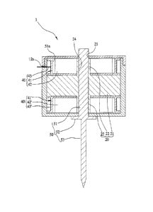
lot of time is
required to mark a section. Also, after removing the posts used for indicating
the section and
bands put around the posts, the posts and the bands are discarded so that
industrial waste is
= produced.
SUMMARY
[0004] The present disclosure provides a section marking
apparatus and method for
geological survey. The section marking apparatus can rapidly and easily divide
a geological
survey site and mark site sections both when the ground surface is flat and
when it is uneven=
or has a slope that makes it difficult to determine a section area. The
section marking
apparatus can be installed and removed easily, and can be secured horizontally
to a ground
surface without any inclination.
= 1
CA 02789717 2012-09-14
[0005] In accordance with an exemplary embodiment, a section marking
apparatus
for geological survey divides a geological survey site into sections and marks
the sections.
The section marking apparatus for geological survey may include a case part; a
fixing shaft
part accommodated in the case part; a section marking part accommodated in the
case part,
coupled to the fixing shaft part, and having a marker string extracted to the
outside of the case
part for guidance to an installation location of another section marking
apparatus; and a
driving pin part coupled to the fixing shaft part and driven into the ground
surface to secure
the section marking apparatus to the ground surface when the section marking
apparatus is
installed.
[0006] In an embodiment, the case part may have an internal space in which
the
fixing shaft part and the section marking part can be received. The fixing
shaft part includes
a partition dividing the internal space of the case part into two spaces, an
upper axial pipe
protruding upward from an upper surface of the partition, and a lower axial
pipe protruding
downward from a lower surface of the partition. The section marking part may
include a first
section marking part accommodated in the case part and disposed above the
partition, and a
second section marking part accommodated in the case part and disposed below
the partition.
[0007] The driving pin part may include a striking rod coupled to the
partition, the
upper axial pipe, and the lower axial pipe, a supporting plate provided below
the striking rod
to support a bottom part of the case part when the striking rod is coupled to
the partition, the
upper axial pipe, and the lower axial pipe, and a driving pin extending
vertically downward
from a lower surface of the supporting plate.
[0008] The first section marking part may include a first drum coupled to
the upper
axial pipe and accommodated in the case part; a first marker string wound
around the first
drum and having one end unwound from the first drum and extracted to the
outside of the
case part; and a first restoring spring provided in the first drum and
connected to the first
marker string to wind the first marker string extracted to the outside of the
case part around
the first drum through the restoration force thereof. Also, the second section
marking part
may include a second drum coupled to the lower axial pipe and accommodated in
the case
part; a second marker string wound around the second drum and having one end
unwound
from the second drum and extracted to the outside of the case part; and a
second restoring
spring provided in the second drum and connected to the second marker string
to wind the
second marker string extracted to the outside of the case part around the
second drum through
the restoration force thereof.
[0009] The case part may include a first extraction hole for extracting
the first marker
2.
CA 02789717 2012-09-14
string and a second extraction hole for extracting the second marker string.
[0010] In another embodiment, the section marking apparatus may include a
connecting part provided on the case part, and the first marker string and the
second marker
string may connect to respective neighboring section marking apparatuses when
the section
marking apparatus is installed.
[0011] The connecting part may include a first connecting hook provided at
a first
end portion of the first marker string extracted to the outside of the case
part and a second
connecting hook provided at a second end portion of the second marker string
extracted to the
outside of the case part. The connecting part may also include a first hook
connecting ring
and a second hook connecting ring provided on an outer surface of the case
part to allow the
first connecting hook or the second connecting hook of another neighboring
section marking
apparatus to be coupled thereto when the section marking apparatus is
installed.
[0012] In still another embodiment, the section marking apparatus may
include a
securing bolt extending through the side part of the case part and coupled to
the partition of
the fixing shaft part.
[0013] In still another embodiment, the section marking apparatus may
include a level
adjusting unit coupled to the side part of the case part to allow the section
marking apparatus
to be secured to the ground surface in a state where the section marking
apparatus is not
inclined but parallel to a horizontal plane when the section marking apparatus
is provided on
the ground surface.
[0014] The level adjusting unit may include a first level provided on a
side part of the
case part in a state where one end portion of the first level is directed in a
first direction, and a
second level provided on the same or another side part of the case part in a
state where one
end portion of the second level is directed in a second direction.
[0015] In addition to the above, some embodiments of the present invention
provide a
section marking apparatus for dividing a geological survey site into one or
more sections,
where the apparatus includes: (a) a case part having a first internal space
formed therein; (b) a
fixing shaft part accommodated in the first internal space to divide the first
internal space; (c)
a first section marking part accommodated in the first internal space and
disposed above the
fixing shaft part, the first section marking part including a first marker
string configured to be
extracted to the outside of the case part; (d) a second section marking part
accommodated in
the first internal space and disposed below the fixing shaft part, the second
section marking
part including a second marker string configured to be extracted to the
outside of the case
part; and (e) a driving pin part including a striking rod extending through
the case part and
CA 02789717 2014-08-25
55013-3
the fixing shaft part, a supporting plate formed at one end portion of the
striking rod to
support a bottom part of the case part, and a driving pin extending from the
supporting plate
and configured to be inserted into the site.
[0016] Other embodiments of the present invention provide
a section marking
= apparatus that includes: (a) a case part having a first extraction hole
and defining a first
internal space; (b) a fixing shaft part accommodated in the first internal
space and having an
upper axial pipe; (c) a first section marking part accommodated in the first
internal space and
having: (i) a first drum including a first winding part and defining a hole
through which the
upper axial pipe extends; (ii) a first marker string wound around an outer
surface of the first
winding part and configured to be extracted to the outside of the case part
through the first
extraction hole; and (iii) a first restoring spring accommodated in a space
formed by an inner
= surface of the first winding part and having a first end portion coupled
to the upper axial pipe
. and a second end portion coupled to the first marker string.
[0017] Still other embodiments of the present invention
provide a method for dividing
a site into one or more sections using a first section marking apparatus, the
method including:
(a) extracting a first marker string from a first extraction hole in a case
part of the first section
marking apparatus, where the case part accommodates a first drum and a first
restoring = =
spring, where the first restoring spring is coupled to the first marker
string, and where the
extracting the first marker string includes unwinding the first marker string
from around an
outer surface of the first drum by overcoming a first restoration force of the
first restoring =
spring; and (b) connecting an end portion of the first marker string to a
second section
marking apparatus.
=
4
CA 02789717 2016-02-23
55013-3
[0017a] According to one aspect of the present invention, there is
provided a section
marking apparatus for dividing a geological survey site into one or more
sections, the
apparatus comprising: a case part having a first internal space formed
therein; a fixing shaft
part accommodated in the first internal space, the fixing shaft part
comprising a partition
dividing the first internal space into an upper space and a lower space; an
upper axial pipe
protruding upward from an upper surface of the partition; and a lower axial
pipe protruding
downward from a lower surface of the partition; a first section marking part
accommodated in
the upper space, the first section marking part including a first drum having
a first bottom part
provided with a hole through which the upper axial pipe extends, and a first
winding part
extending from an edge of the first bottom part and being substantially
perpendicular to the
first bottom part; the first marker string wound around an outer surface of
the first winding
part; and a first restoring spring accommodated in a space formed by an inner
surface of the
first winding part and having a first end portion coupled to the upper axial
pipe and a second
end portion coupled to the first marker string; a second section marking part
accommodated in
the lower space, the second section marking part including a second drum
having a second
bottom part provided with a hole through which the lower axial pipe extends,
and a second
winding part extending from an edge of the second bottom part and being
substantially
perpendicular to the second bottom part; the second marker string wound around
an outer
surface of the second winding part; and a second restoring spring accommodated
in a space
formed by an inner surface of the second winding part and having a first end
portion coupled
to the lower axial pipe and a second end portion coupled to the second marker
string; a driving
pin part including a striking rod extending through the case part, the
partition, the upper axial
pipe and the lower axial pipe to protrude from an upper surface of the case
part, a supporting
plate formed at one end portion of the striking rod to support a bottom part
of the case part,
and a driving pin extending from the supporting plate and configured to be
inserted into the
site; and wherein the first drum and the first winding part of the first
section marking part
rotates with respect to the upper axial pipe, and the second drum and the
second winding part
of the second section marking part rotates with respect to the lower axial
pipe independently
of the first drum and the first winding part, and wherein the first and second
section marking
parts have a same rotation axis which is coincide with the striking rod.
4a
CA 02789717 2016-02-23
, .
55013-3
BRIEF DESCRIPTION OF THE DRAWINGS
[0018] Exemplary embodiments can be understood in more detail
from the following
description taken in conjunction with the accompanying drawings, in which:
[0019] FIG. 1 is an exploded perspective view showing a
structure of a section
marking apparatus for geological survey according to one embodiment of the
present
invention;
[0020] FIG. 2 is a perspective view showing a coupled state of
the apparatus of
FIG. 1;
[0021] FIG. 3 is a cross-section through the apparatus of FIG.
2;
[0022] FIG. 4 is a plan view of the apparatus of FIG. 2 from which a
cover is
removed;
4b
CA 02789717 2012-09-14
[0023] FIG. 5 is a plan view showing a state of a section
marking apparatus for
geological survey according to one embodiment of the present invention in
which a marker
string is extracted;
[0024] FIG. 6 is a plan view illustrating a structure of a
section marking apparatus for
geological survey according to another embodiment of the present invention;
[0025] FIG. 7 is a plan view showing a plurality of the
apparatuses to mark a section
for a geological survey shown in FIG. 6 connected to each other;
[0026] FIG. 8 is an exploded perspective view of a part of a
section marking
apparatus for geological survey according to yet another embodiment of the
present
invention;
[0027] FIG. 9 is a perspective view of a section marking
apparatus for geological
survey to which a securing bolt shown in FIG. 8 is coupled;
[0028] FIG. 10 is a perspective view showing a structure of a
section marking
apparatus for geological survey according to yet another embodiment of the
present
= invention;
[0029] FIG. 11 is a plan view showing a top surface of a
section marking apparatus
for geological survey shown in FIG. 10; and
[0030] FIG. 12 is an exploded perspective view for
illustrating a section marking
apparatus for geological survey according to a second embodiment of the
present invention.
DETAILED DESCRIPTION OF EMBODIMENTS
[0031] Exemplary embodiments will be described in detail with
reference to the
accompanying drawings. Since the present disclosure may have modified
embodiments,
preferred embodiments are illustrated in the drawings and are described in the
detailed
description of the invention. However, this does not limit the present
disclosure within
specific embodiments and it should be understood that the present disclosure
covers all the
modifications, equivalents, and replacements within the idea and technical
scope of the
present disclosure. In the drawings, the dimensions and size of each structure
may be
exaggerated, omitted, or schematically illustrated for convenience in
description and clarity.
[0032] It will be understood that although the terms of first
and second are used
herein to describe various elements, these elements should not be limited by
these terms.
Terms are only used to distinguish one component from other components.
Therefore, a
component referred to as a first component in one embodiment can be referred
to as a second
component in another embodiment.
CA 02789717 2012-09-14
[0033] In the following description, the technical terms are used only for
explaining a
specific exemplary embodiment while not limiting the present disclosure. The
terms of a
singular form may include plural forms unless referred to the contrary. The
meaning of
'include', 'have', or 'comprise' specifies a property, a step, a function, an
element, or a
combination thereof, but does not exclude other properties, steps, functions,
elements, or
combinations thereof
[0034] Unless terms used in the present description are defined
differently, the terms
should be construed as having the one or more meanings known to those skilled
in the art.
Terms that are generally used and have been defined in dictionaries should be
construed as
having meanings matched with contextual meanings in the art. In this
description, unless
defined clearly, terms are not ideally or excessively construed as formal
meanings.
[0035] FIG. 1 is an exploded perspective view showing a structure of a
section
marking apparatus for geological survey in accordance with an exemplary
embodiment. FIG.
2 is a perspective view showing a coupled state of the apparatus of FIG. 1.
FIG. 3 is a cross-
section through the apparatus of FIG. 2. FIG. 4 is a plan view of the
apparatus of FIG. 2 from
which a cover is removed.
[0036] Referring to FIG. 1 to FIG. 4, a section marking apparatus 1 for a
geological
survey in accordance with an exemplary embodiment may include a case part 10,
a fixing
shaft part 20, section marking parts 40 and 40', and a driving pin part 50.
[0037] The fixing shaft part 20 and the section marking parts 40 and 40'
may be
accommodated in the case part 10. For example, the case part 10 may include a
bottom part
11, a side part 12, and a cover part 13 for forming an internal space in which
the fixing shaft
part 20 and the section marking parts 40 and 40'are received.
[0038] The bottom part 11 may have a circular plate-shape or a rectangular
plate-
shape. An insertion hole lla may be formed at a center of the bottom part 11
to allow a
striking rod 51 of the driving pin part 50 to be inserted into the insertion
hole 11 a.
[0039] The side part 12 may extend vertically upward from an edge of the
bottom part
11. For example, the side part 12 can be formed integrally with the bottom
part 11. The side
part 12 may be provided with a first extraction hole 12a and a second
extraction hole 12b.
The first extraction hole 12a enables a first marker string 43 of the first
section marking part
40 of the section marking parts 40 and 40' to be extracted to the outside, and
the second
extraction hole 12b enables a second marker string 43' of the second section
marking part 40'
of the section marking parts 40 and 40' to be extracted to the outside. The
first extraction
(o
CA 02789717 2012-09-14
hole 12a and the second extraction hole 12b are formed on the side part 12
such that the first
marker string 43 and the second marker string 43' can be extracted in a state
where two
strings are perpendicular to each other. The second extraction hole 12b may be
formed below
the first extraction hole 12a.
[0040] The cover part 13 is opposite to the bottom part 11 and
coupled detachably to
an upper end of the side part 12 to enable the internal space of the case part
10 to be opened
and sealed. For example, the cover part 13 can be coupled to the side part 12
by a screw-
coupling. In this case, thread portions which may be screw-coupled to each
other can be
formed on an upper portion of an outer circumference surface of the side part
12 and an inner
circumference surface of the cover part 13, respectively. A hole 13a may be
formed at a
center of the cover part 13 to enable the striking rod 51 to pass through the
hole 13a.
[0041] The above case part 10 may be formed of material such
as metal, plastic, or
the like. However, the material to be used to form the case part 10 is not
limited thereto as
long as it has a certain strength.
= [0042] The fixing shaft part 20 may divide the internal space of
the case part 10 into
two spaces to enable the section marking parts 40 and 40' to be accommodated
in the fixed
places. The fixing shaft part 20 may include a partition 21, an upper axial
pipe 22, and a
lower axial pipe 23.
[0043] The partition 21 may divide the internal space of the
case part 10 into two
spaces. The partition 21 may have a plate shape having a dimension which is
virtually the
same as a cross-section of the internal space of the case part 10.
[0044] The upper axial pipe 22 and the lower axial pipe 23 may
be accommodated in
the internal space of the case part 10 to allow central portions of the first
section marking part
40 and the second section marking part 40' to coincide with a center portion
of the partition
21. The upper axial pipe 22 may protrude upward from an upper surface of the
partition 21,
and the lower axial pipe 23 may protrude downward from a lower surface of the
partition 21.
Holes 24 through which the striking rod 51 may pass may be formed on the
partition 21, the
upper axial pipe 22, and the lower axial pipe 23, respectively, the holes 24
being in
communication with each other. The upper axial pipe 22 may be provided with a
first cut-out
section 22a, and the lower axial pipe 23 may be provided with a second cut-out
section 23a.
The first cut-out section 22a enables one end of a first restoring spring 42
mounted to the first
section marking part 40 of the section marking parts 40 and 40' to be secured
to the upper
axial pipe 22, and the second cut-out section 23a enables one end of a second
restoring spring
7
CA 02789717 2012-09-14
=
42' mounted to the second section marking part 40' of the section marking
parts 40 and 40' to
be secured to the lower axial pipe 23.
[0045] The fixing shaft part 20 described above may be formed of material
such as
metal, plastic, or the like. However, material employed for forming the fixing
shaft part 20 is
not limited thereto as long as it has a certain strength. In addition,
material employed for
forming the fixing shaft part 20 may be the same as or different from that
employed for
forming the case part 10.
[0046] The section marking parts 40 and 40'may divide a geological survey
site into
square sections or rectangular sections and indicate the divided sections. The
section
marking parts 40 and 40' may include the first section marking part 40 and the
second section
marking part 40', which are accommodated in the internal space of the case
part 10. The first
and second section marking parts 40 and 40' may be disposed across the
partition 21 from
each other.
[0047] The first section marking part 40 may be accommodated in an upper
space of
the internal space of the case part 10 which is divided into two spaces by the
partition 21.
The first section marking part 40 may include a first drum 41, the first
restoring spring 42,
and the first marker string 43.
[0048] The first drum 41 may accommodate the first restoring spring 42 and
the first
marker string 43 may be wound around the first drum 41. As one example, in
order to
accommodate the first restoring spring 42 and wind the first marker string 43,
the first drum
41 may include a first bottom part 41a and a first winding part 41b. The first
bottom part 41a
may be a plate having a circular shape, and a hole through which the upper
axial pipe 22
passes may be formed at a center of the first bottom part 41a. The first drum
41 may be
rotated with respect to the upper axial pipe 22 inserted into the hole of the
first bottom part
41a and acting as a rotational axis. The first winding part 41b is formed as a
side surface of
the first drum 41 and may extend upward perpendicularly from an edge of the
first bottom
part 41a. As one example, the first bottom part 41a and the first winding part
41b may be
formed integrally with each other. The first winding part 41b may have a
cylindrical pipe
shape, and an internal space of the first winding part 41b may have an opened
upper end to
enable the first restoring spring 42 to be inserted into the internal space of
the first winding
part 41b. An insertion hole may be formed on one side of the first winding
part 41b for
inserting the first marker string 43 into an inner space of the first winding
part 41b. The first
drum 41 may be formed of material such as metal, plastic, or the like.
However, the material
8
CA 02789717 2012-09-14
=
employed for forming the first drum 41 is not limited as long as it has a
certain strength, and
the first bottom part 41a and the first winding part 41b may be formed of the
same material or
different materials.
[0049] The first restoring spring 42 may make the first marker string 43
unwound
from the first drum 41 be wound around the first drum 41 again. The first
restoring spring 42
may be received in the internal space of the first drum 41. For example a
conventional spiral
spring may be utilized as the first restoring spring 42. An inner end portion
of the first
restoring spring 42 may be secured to the first cut-out section 22a of the
upper axial pipe 22,
and an outer end portion of the first restoring spring 42 may be coupled to
one end portion of
the first marker string 43 inserted through the hole formed on the first
winding part 41b.
[0050] The first marker string 43 may have a certain length and may be
wound
around the first drum 41. For example, in order to wind the first marker
string 43 around the
first drum 41, one end of the first marker string 43 may be inserted into the
insertion hole
formed on the winding part 41b of the first drum 41, and then fixed to the
outer end portion
of the first restoring spring 42. The other end of the first marker string 43
may be extracted
to the outside of the case part 10 through the first extraction hole 12a
formed on the side part
12 of the case part 10. In a case where the first marker string 43 is
connected to the first
drum 41 and the first restoring spring 42 as described above, when the first
marker string 43
may be pulled and extracted to the outside of the case part 10, the first drum
41 may be
rotated about the upper axial pipe 22 so that the first marker string 43 may
be unwound from
the first drum 41, and if the pulled first marker string 43 is released, the
first marker string 43
may be wound again around the first drum 41 by the restoration force of the
first restoring
spring 42.
[0051] The second section marking part 40' may be accommodated in a lower
space
of the internal space of the case part 10 which is divided into two spaces by
the partition 21.
The second section marking part 40' may include a second drum 41', the second
restoring
spring 42', and the second marker string 43'.
[0052] The second drum 41' may accommodate the second restoring spring
42', and
the second marker string 43' may be wound around the second drum 41'. As one
example, in
order to accommodate the second restoring spring 42' and wind the second
marker string 43',
the second drum 41' may include a second bottom part 41a' and a second winding
part 41b'.
The second bottom part 41a' may be a plate having a circular shape, and a hole
through
which the lower axial pipe 23 passes may be formed at a center of the second
bottom part
41a'. The second winding part 41b' is formed as a side surface of the second
drum 41' and
9'
CA 02789717 2012-09-14
may extend downward perpendicularly from an edge of the second bottom part
41a'. As one
example, the second bottom part 41a' and the second winding part 41b' may be
formed
integrally with each other. The second winding part 41b' may have a
cylindrical pipe shape,
and an internal space of the second winding part 41b' may have an opened lower
end to
enable the second restoring spring 42' to be inserted into the internal space
of the second
winding part 41b'. An insertion hole may be formed on one side of the second
winding part
41b' for inserting the second marker string 43' into an inner space of the
second winding part
41b'. The second drum 41' may be formed of material such as metal, plastic, or
the like.
However, the material employed for forming the second drum 41' is not limited
as long as it
has a certain strength, and the second bottom part 41a' and the second winding
part 41b' may
be formed of the same material or different materials.
[0053] The second restoring spring 42' may make the second marker string
43'
unwound from the second drum 41' be wound around the second drum 41' again.
The
second restoring spring 42' may be received in the internal space of the
second drum 41'. A
conventional spiral spring may be utilized as the second restoring spring 42'.
An inner end
portion of the second restoring spring 42' may be secured to the second cut-
out section 23a of
the lower axial pipe 23, and an outer end portion of the second restoring
spring 42' may be
coupled to one end portion of the second marker string 43' inserted through
the hole formed
on the second winding part 41b'.
[0054] The second marker string 43' may have a certain length and may be
wound
around the second drum 41'. For example, in order to wind the second marker
string 43'
around the second drum 41', one end of the second marker string 43' may be
inserted into the
insertion hole formed on the winding part 41b' of the second drum 41', and
then fixed to the
outer end portion of the second restoring spring 42'. The other end of the
second marker
string 43' may be extracted to the outside of the case part 10 through the
second extraction
hole 12b formed on the side part 12 of the case part 10. In a case where the
second marker
string 43' is connected to the second drum 41' and the second restoring spring
42' as
described above, when the second marker string 43' is pulled and extracted to
the outside of
the case part 10, the second drum 41' is rotated about the lower axial pipe 23
so that the
second marker string 43' is unwound from the second drum 41', and if the
pulled second
marker string 43' is released, the second marker string 43' may be wound again
around the
second drum 41' by the restoration force of the second restoring spring 42'.
[0055] The driving pin part 50 allows the section marking apparatus 1 to be
secured
to a ground surface. The driving pin part 50 may be coupled to the fixing
shaft part 20 and
CA 02789717 2012-09-14
the case part 10. As one example, the driving pin part 50 is coupled to the
fixing shaft part 20
and the case part 10, and may include the striking rod 51, a supporting plate
52, and a driving
pin 53 to secure the section marking apparatus 1 to a ground surface.
[0056] The striking rod 51 may be struck by a hammer to drive the driving
pin 53 into
the ground surface when the section marking apparatus 1 is fixed to the ground
surface. The
striking rod 51 may be a vertically elongated rod having a dimension which is
virtually the
same as a section of the holes 24 formed on the partition 21, the upper axial
pipe 22, and the
lower axial pipe 23. The striking rod 51 may be forcibly inserted into the
insertion hole 11 a
formed on the lower part of the case part 10 and the holes 24 formed on the
partition 21.
[0057] The supporting plate 52 may be disposed below the striking rod 51
to restrict a
length of the striking rod 51 which is forcibly inserted into the fixing shaft
part 20 and
prevent the case part 10 from moving downward along the striking rod 51 due to
its own
weight or an external impact. The supporting plate 52 may be a plate having a
circular shape
or a polygonal shape such as a quadrangle, hexagon, or the like. The
supporting plate 52 may
be supported on the bottom part 11 of the case part 10 when the striking rod
51 is coupled to
the fixing shaft part 20.
[0058] The driving pin 53 may extend downward perpendicularly from a
center of a
lower surface of the supporting plate 52. The driving pin 53 may have a
pointed end so that
the driving pin 53 may be driven into the ground surface, and may have a
certain strength and
a diameter smaller that the striking rod 51 and the supporting plate 52.
[0059] The driving pin 53 as described above may be formed of material
such as
metal having a length by which the driving pin 53 may withstand an external
impact.
Provided the driving pin 53 has a certain length which is sufficient to be
driven into the
ground surface, the material employed for forming the driving pin 53 is not
limited.
[0060] When the section marking apparatus 1 for a geological survey
according to the
first embodiment of the present invention is secured to the ground surface for
dividing the
site and marking the sections, the striking rod 51 is stricken by a hammer and
the striking pin
53 is driven into the ground surface to enable the section marking apparatus 1
to be secured
to the ground surface. FIG. 5 is a plan view showing a state of the section
marking apparatus
1 for geological survey according to the first embodiment of the present
invention in which
the marker string is extracted. Referring to FIG. 5, once the section marking
apparatus 1 is
secured to the ground surface, the first marker string 43 and the second
marker string 43' are
extracted to the outside of the case part 10. That is, the first marker string
43 and the second
marker string 43' are extracted to front areas of the first extraction hole
12a and the second
II
CA 02789717 2012-09-14
extraction hole 12b so that the first extraction hole 12a and the second
extraction hole 12b
guide a location to which another section marking apparatus I will be secured.
Accordingly,
the securing location of another section marking apparatus 1 may be easily
recognized. Due
to the above, in any case where the ground surface is even and a height of the
ground surface
is not constant, that is, in a case where the ground surface is uneven or has
a slope that makes
it difficult to determine a section area, the processes for dividing the
geological survey site
and indicating sections may be rapidly executed.
[0061] FIG. 6 is a plan view illustrating a structure of the section
marking apparatus 1
for geological survey in accordance with another exemplary embodiment. FIG. 7
is a plan
view showing a plurality of the apparatus to mark a section for a geological
survey shown in
FIG. 6 connected to each other.
[0062] Referring to FIG. 6 and FIG. 7, the section marking apparatus 1 for
a
geological survey may further include a connecting part 60.
[0063] When the section marking apparatus 1 is installed on the ground
surface, the
connecting part 60 enables the first marker string 43 and the second marker
string 43' to be
connected to another neighboring the section marking apparatus 1. For example,
the
connecting part 60 may include a first connecting hook 61, a second connecting
hook 62, a
first hook connecting ring 63, and a second hook connecting ring 64.
[0064] The first connecting hook 61 may be provided at one end of the
first marker
string 43 extracted through the first extraction hole 12a of the case part 10,
and the second
connecting hook 62 may be provided at one end of the second marker string
43'extracted
through the second extraction hole 12b of the case part 10.
[0065] The first connecting hook 61 and the second connecting hook 62 of
the
neighboring apparatuses 1 to mark a section may be secured to the first hook
connecting ring
63 and the second hook connecting ring 64, respectively. The first hook
connecting ring 63
and the second hook connecting ring 64 may be provided on the side part 12 of
the case part
10. The first hook connecting ring 63 may be provided at a location which is
opposite to the
second connecting hook 62, and the second hook connecting ring 64 may be
provided at a
location which is opposite to the first connecting hook 61.
[0066] In a case where the section marking apparatus I is further provided
with the
connecting part 60 as described above, as shown in FIG. 7, the first marker
string 43 and the
second marker string 43' of each section marking apparatus may be connected to
a
neighboring section marking apparatus in a state where the section marking
apparatuses are
fixed to the ground surface.
CA 02789717 2012-09-14
[0067] FIG. 8 is an exploded perspective view for illustrating a structure
of a section
marking apparatus 1 for geological survey in accordance with still another
embodiment. FIG.
9 is a perspective view of a section marking apparatus 1 for geological survey
to which a
securing bolt shown in FIG. 8 is coupled.
[0068] Referring to FIG. 8 and FIG. 9, the section marking apparatus 1 for
a
geological survey may further include a securing bolt 70.
[0069] The securing bolt 70 may couple the case part 10 with the fixing
shaft part 20.
As one example, a through hole 14 through which the securing bolt 70 may pass
may be
formed on the side part 12 of the case part 10, and the partition 21 of the
fixing shaft part 20
may have a threaded hole 21a formed thereon. Here, the through hole 14
corresponds to this
threaded hole 21a, and the securing bolt 70 passing through the side part 12
of the case part
may be screw-coupled to the threaded hole 21a. In a case where the case part
10 and the
fixing shaft part 20 are coupled to each other by the securing bolt 70 as
described above, in a
state where the fixing shaft part 20 is fixed at a predetermined place, the
fixing shaft part 20
may be accommodated in the internal space of the case part 10.
[0070] FIG. 10 is a perspective view showing a structure of a section
marking
apparatus I for geological survey in accordance with another embodiment of the
present
invention. FIG. 11 is a plan view showing a top surface of a section marking
apparatus 1 for
geological survey shown in FIG. 10.
[0071] Referring to FIG. 10 and FIG. 11, the section marking apparatus 1
for a
geological survey may further include a level adjusting unit 80.
[0072] The level adjusting unit 80 allows the section marking apparatus I
to be
secured to the ground surface in a state where the section marking apparatus 1
is not inclined
but parallel to a horizontal plane when the section marking apparatus 1 is
provided on the
ground surface. As one example, the level adjusting unit 80 may include a
first level 81 and a
second level 82. The first level 81 is provided on one side of the side part
12 of the case part
10 and may be directed in the first lateral direction. The second level 82 is
provided on the
other side of the side part 12 of the case part 10 and may be directed in the
second lateral
direction which is perpendicular to the first lateral direction. As the first
level 81 and the
second level 82, a manual type level which works by checking whether a bubble
in a liquid
contained in a transparent tube is located within gradations marked on the
transparent tube
may be employed, and a digital level may be utilized.
[0073] As described above, if the section marking apparatus 1 is provided
with the
level adjusting unit 80, when the section marking apparatus 1 is installed on
the ground
I 5
CA 02789717 2012-09-14
surface, the user may secure the section marking apparatus 1 to the ground
surface while the
user checks the first level 81 and the second level 82, and so the section
marking apparatus 1
may be secured on the ground surface without any inclination.
[0074] FIG. 12 is an exploded perspective view for illustrating a section
marking
apparatus 2 according to another embodiment.
[0075] Referring to FIG. 12, a section marking apparatus 2 according to a
second
embodiment of the present invention may include a case part 110, a fixing
shaft part 120,
section marking parts 140, 140', a driving pin part 150, a connecting part
160, a securing bolt
170, a level adjusting unit 180, and a marker string guiding part 190.
[0076] The structures of the case part 110, the fixing shaft part 120, the
section
marking parts 140 and 140', the driving pin part 150, the connecting part 160,
the securing
bolt 170, and the level adjusting unit 180 included in the section marking
apparatus 2
according to the second embodiment of the present invention are substantially
the same as or
similar to those of the case part 10, the fixing shaft part 20, the section
marking parts 40, 40',
the driving pin part 50, the connecting part 60, the securing bolt 70, and the
level adjusting
unit 80 of the section marking apparatus 1 according to the first embodiment
of the present
invention, which are described above with reference to FIG. 1 to FIG. 11.
Thus, for a
detailed description of these elements, refer to the description regarding
FIG. 1 to FIG. 11.
[0077] The marker string guiding part 190 may guide extraction directions
of the first
and second marker strings to enable the first marker string to be extracted
perpendicular to
the direction in which the second marker string is extracted. The marker
string guiding part
190 is secured between the bottom part of the case part 110 and a supporting
plate of the
driving pin part 150, and may have a shape of a circular plate having a
diameter larger than
the bottom part of the case part 110. The marker string guiding part 190 may
have a hole
formed at a center thereof to allow a striking rod of the driving pin part 150
to pass through
the hole. On an upper surface of the marker string guiding part 190, in
addition, a first line
indicating the extraction direction of the first marker string, a second line
indicating the
extraction direction of the second marker string, and a third line and a
fourth line for
verifying the extraction directions of the first and second marker strings of
the neighboring
section marking apparatuses may be formed. The first, second, third, and
fourth lines may be
extending in the mutually perpendicular directions with respect to a hole
through which the
striking rod passes.
[0078] According to the section marking apparatus for geological survey in
accordance with exemplary embodiments, both when the ground surface is flat
and when it is
CA 02789717 2014-08-25
55013-3 =
uneven or has a slope so that it is difficult to grasp a section area, the
processes for dividing a
geological survey site and marking the sections may be easily executed. In
addition, in
accordance with some embodiments, the section marking apparatus is
advantageous in that it
. is easy to install and remove, and it is possible to horizontally
secure the section marking ..
apparatus to the ground surface without any inclination.
[0079] Although exemplary embodiments have been described it will be
readily
understood by those skilled in the art that various modifications and changes
can be made
thereto without departing from the scope of the present disclosure defined by
the
appended claims.
=