Note: Descriptions are shown in the official language in which they were submitted.
CA 02789761 2012-08-14
WO 2011/103143 PCT/US2011/025018
1
Array of Micromolded Structures for Sorting Adherent Cells
Nancy Allbritton, Christopher Sims, and Yuli Wang
This invention was made with Government support under grant numbers EB007612,
HG4843 and HG4843S1 from the National Institutes of Health. The US Government
has
certain rights to this invention.
Background of the Invention
The selection and isolation of single cells from a mixed population is a
common
procedure performed throughout biomedical research. For example, during the
development
of cell lines that are genetically engineered, derived from stem cells, or
grown from patient
cell lines, single cells must be isolated and then cloned to form a
homogeneous population. A
variety of strategies exist to selectively identify and collect nonadherent
cells from a mixed
population, including fluorescence activated cell sorting (FACS), limiting
dilution, panning,
column chromatography and magnetic sorting; furthermore, new techniques based
on
microfluidics and dielectrophoresis show promise in this area.1-6 To address
the need to
collect pure or enriched populations of adherent cells, investigators use
these procedures by
disaggregating or stripping the cells from their growth surface to create cell
suspensions.
Unfortunately, enzymatic or mechanical release imposes significant drawbacks
including loss
of cell morphology, removal of cell surface markers, damage to cell membranes,
alterations
in cellular physiology and loss of viability:1-14
New techniques for adherent, mammalian cell selection address some of the
challenges but remain limited for living cells. Laser capture microdissection
(LCM)
(Arcturus; Mountain View, CA) has enabled single cells or small groups of
selected cells to
be obtained from tissue sections for genetic and proteomic studies, although
most
applications utilize fixed or frozen specimens.15 Protocols for use with live
cells have been
published, but are very low throughput and not suitable for isolating large
numbers of single,
living cells.16 Most applications of LCM utilize fixed or frozen specimens.15-
18 Thus, these
techniques have only partially met the needs of investigators for the positive
selection of
adherent, mammalian cells. P.A.L.M. Microlaser Technologies (Bernried,
Germany) markets
CA 02789761 2012-08-14
WO 2011/103143
PCT/US2011/025018
2
an instrument that uses a laser to cut out a region of interest from a tissue
section and then
generate a shock wave that "catapults" the cells into an overlying collection
device.I7 Again
most of the work with this technique has utilized fixed specimens, but
collection of living
cells has been demonstrated.I8 Cells are subjected to stress due to the direct
effects of the
shock wave and desiccation from removal of fluid overlying the sample during
collection.
ClonePix (Genetix, Hampshire, UK) is an automated system that uses image
recognition to
guide a suction pipette that aspirates colonies of loosely adherent cells from
plates. The
system requires cells that grow in loosely adherent clusters or suspension-
adapted versions of
adherent cells growing in a semi-solid methylcellulose media, thus it is not
applicable to the
vast majority of mammalian cells.
Recently, the Allbritton group developed an array technology for sorting
adherent
eells.19-23 This cell sorting strategy uses arrays of releasable,
microfabricated elements,
termed pallets, formed from the biocompatible epoxy photoresist, either
formulated from
EPON SU-8 or 1002F epoxy resins.19' 24 The epoxy is photolithographically
defined on a
.. standard microscope slide to create the pallet array. The pallets can be
varied in size from
tens to hundreds of microns to provide an adequate growth area for single
cells or large
colonies. In addition, the pallet surfaces can be modified with proteins or
gels to enhance cell
attachment and growth.I9' 25' 26 To culture cells on these arrays, cells are
initially placed in
suspension, but are allowed to settle and grow on individual pallets prior to
analysis. When
cells are plated on the array, the virtual air wall or polyethylene glycol
hydrogel wall limit the
location for cell attachment to the upper pallet surface.19' 23 Since the
aiTay is transparent,
cells can be analyzed by standard microscopy techniques during culture.
Subsequent to
analysis, individual pallets containing the desired cells are released from
the array using a
pulsed laser and are then collected.29' 22 Recent studies of the selection and
expansion of
single cells have demonstrated a high rate of viability after laser-based
release and
exceptional success in clonal expansion of individual, sorted cells.21' 22 The
approach makes
possible a range of cell selection criteria for determining cells of interest
(e.g. phenotrypic
and temporal criteria and other characteristics) not accessible by alternative
methods.22 The
pallet array has recently been used as a platform for culturing and sorting
stem cell, and
sorting cells based on antibody affinity.27' 28
Although some unique advantages have been demonstrated for the pallet array
over
other cell sorting technologies, several limitations need to be overcome
before it can be
widely accepted by the biology research community. The most serious limitation
is that an
3
expensive optical system is required to release a target pallet from the
array. The optical system
(including pulsed laser, beam splitter, mirror and lens) must be precisely
aligned and maintained. To
effectively release a pallet from the glass surface on which it is formed, the
beam of the laser
must be focused precisely at the interface between pallet and glass within a
distance of a few
micrometers.29 To assist the user to find the right laser focal plane,
indicators need to be
built on the pallet array which adds complexity to fabrication. The shock wave
generated by the
laser is detrimental to the viability of cells, and as a result the energy of
each laser pulse must be
restricted to be less than 51.t.1 in order to maintain high post-sort cell
viability. However, a very
low energy of release requires precise control of the adhesion force between
the pallet and glass
to keep pallets attached to the array until released is desired. In addition
to the limitations
required for laser-based release, the pallet array itself has drawbacks.
First, the pallet array is made
from photoresist having autofluorescence in the range of 480-520 nm, which
coincides with the
range of wavelengths of the most frequently used dyes (e.g. FITC, Oregon
green, Alexa Fluor
488, ctc) for fluorescence imaging.22. 24 Second, the fabrication of the
pallet array is expensive
and complicated, since the whole fabrication process needs a clean environment
and expensive
microfabrication tools including mask aligner, photoresist spin coater, metal
evaporator, and plasma
cleaner.I9
Accordingly, there is a need for new ways to construct microcarriers useful
for cell
sorting.
Summary of the Invention
In one aspect, there is provided an apparatus for collecting or culturing
cells or cell colonies,
said apparatus comprising: a
substrate formed from an elastomer and having a first surface and
an opposed second surface and a plurality of wells formed in the first surface
in the form of an
array; and a
plurality of rigid cell carriers, each carrier disposed in one of said wells
such that
the carrier is resiliently received in the one of said wells, the carriers
configured to release from said
substrate upon mechanical distortion of said substratc.
In another aspect, there is provided a method of collecting cells or cell
colonies,
comprising: (a) providing an apparatus comprising a substrate formed from an
elastomer and
having a first surface and an opposed second surface and a plurality of wells
formed in the first
surface in the form of an array, and a plurality of rigid cell carriers, each
carrier disposed in one of
said wells, the carriers configured to release from said substrate upon
mechanical distortion of said
substrate; (b) depositing a liquid media carrying said cells on said apparatus
so that said cells settle
on or adhere to said cell carriers; (c) releasing at least one selected
CA 2789761 2017-08-24
4
carrier having said cells thereon by application of gradual mechanical pushing
energy to
the second surface of the substrate opposite the well in which the at least
one selected carrier is
disposed until the at least one selected carrier is released; and then (d)
collecting said at least one
selected carrier.
The present invention is explained in greater detail in the drawings herein
and the
specification set forth below. The disclosures of all United States patent
references cited herein are
to be incorporated by reference herein in their entirety.
Brief Description of the Drawings
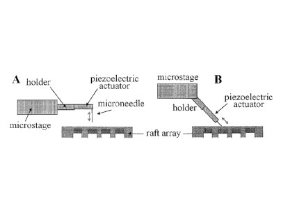
Figure 1. Shown are schematics (A,B) of raft release hardware and geometry.
Figure 2. Schematic of array scaffold and raft collection plate. A) Side view
of the mold
mated to the scaffold/collection plate. B & C) Top view of scaffold/collection
plate only. Either
support walls (B) or posts (C) are present. D) Side view of mated array and
scaffold/collection
plate with vias shown for array washing.
Figure 3. Fabrication of microwell array bottomed with micromolded concave
rafts. (A)
Schematic of the fabrication process. i) A polydimethylsiloxane (PDMS)
microwell array was
fabricated by standard molding process. ii) A polymer solution was cast on the
PDMS microwell
array. iii) Polymer solution flew from the array and resulted in isolated
polymer convex solution in
each well. iv) Evaporation of solvent resulted in a concave polymer raft
forming the base of each
well. (B) Transmitted light micrograph of polymer convex solution in the array
of microwells (100
p.m square, 30 lam gap). (C) Transmitted light micrograph of polymer convex
rafts in the microwell
array after evaporation of solvent (100 pm square, 30 pm gap). (D) SEM image
of a microwell
array (175 m square, 40 pm gap) with raft bases. (E) A close-up of an SEM
image of a ruptured
section showing that the concave raft has little adhesion to the PDMS well so
that it can be easily
detached.
Figure 4. Fluorescence of films of SU-8 photoresist (50-um thickness), 1002F
photoresist
(50- m thickness), 1009F resin (50- m thickness), and PDMS (120- m thickness)
using common
microscopy filter sets. Films of varying thickness were coated onto glass
slides. The fluorescence
intensity of the films was measured using a fluorescein filter set (hatched
bars), a TRITC filter set
(white bars), or a Cy5 filter set (black bars).
Figure 5. Release of individual rafts from the array by needle release. A)
Experimental
setup of the needle release system. The needle was fixed on a transparent
CA 2789761 2017-08-24
CA 02789761 2012-08-14
WO 2011/103143 PCT/US2011/025018
polycarbonate block, and the position of the needle was controlled by an x-y-z
manipulator.
The manipulator was installed on the stage of an inverted microscope. B)
Micrographs of
needles used for release (from top to bottom): tungsten carbide, anodized
steel, tungsten. The
scale bar is 100 1-1,M. C) Shown is an array of square molded rafts (50 lam
side, 15 [im height,
5 25 jim spacing). The rafts marked with an asterisk were released as shown
in (E). I)) The
fluorescence image of the raft array in (C). The polymer solution used to form
the rafts was
mixed with 100 ppm of rhodamine B in order to visualize the rafts by
fluorescence
microscopy, E) The four rafts marked in (C) were sequentially released with a
needle. F) The
fluorescence image of the raft array in (E). After release, the four rafts
dropped from the array
.. into the collection dish.
Figure 6. Patterning of cells on the microwell array bottomed with detachable
rafts.
(A) and (B) Single HeLa cells were patterned on a 30 ni microwell array (15
p.m depth,
inter-well gap of 120 tm; height of pallet: 9 pm). (C) and (D) A multiple of
HeLa cells were
patterned on a 100 p.m microwell array (50 1.im depth, inter-well gap of 50
t.tm; height of
base: 15 inn). (A) and (C) are transmitted light micrograph images, and (B)
and (D) are SEM
images.
Figure 7. Needle-based release of adherent cells grown on the concave rafts
from the
microwell array. (A) Schematic of the release process. i) An array of
microwells with
detachable rafts as their base was assembled on a cassette and the surface was
oxidized with
air plasma, ii) Cells were plated on the array and allowed to attach to the
rafts. iii) The
chamber containing the array was filled with medium, covered by a collection
chamber and
the assembly was inverted. The cell of interest (depicted in green) was
separated from the
array by dislodging the raft to which it was attached using a needle. iv) The
raft transported
the isolated cell to a new culture dish. v) The isolated cell continued to
grow. Transmitted
light micrographs showing the selected HeLa cells (marked with an asterisk)
were released
from the array by a needle. (B-D) A single HeLa cell was isolated with a 30
[tm raft. (E-G)
Five HeLa cells were isolated with a 100 1.tm raft, (F-J) A colony of HeLa
cells (number of
cells > 100) was isolated with a 300 ?Am raft. (B), (E) and (H) are images
before needle
penetration. (C), (F) and (I) are images after needle penetration, showing the
targeted rafts
were released without disturbing neighboring rafts. (D), (G) and (J) are
images showing the
targeted cells were transported to the collection dishes by the rafts and that
the released rafts
remained intact.
CA 02789761 2012-08-14
WO 2011/103143 PCT/US2011/025018
6
Figure 8. Proliferation of single cells after needle release, The released
single HeLa
cell on a raft (length x width >< depth = 50 pm x 50 um x 15 um) was
collected, and imaged
at 0 h (A), 24 h (B), 48 (h) and 144 (h) after the initiation of culture.
Figure 9. Isolation of colonies of eGFP-expressing cells. (A) Transmitted
light image
of HeLa cells on an array. (B) Fluorescent image of the cells shown in (A).
(C) Raft with
eGFP-expressing cells was released from the array. Shown is a transmitted
light image
immediately after collection. (D) Shown is the fluorescence image of the cells
and raft shown
in (C). (E) Shown is the same raft in collection well shown in (C) 6 days
after collection. The
cells have expanded into a colony of >200 cells. (F) The fluorescence image of
the raft and
collection well shown in (E).
Figure 10. Brightfield images showing attachment of HeLa cells on the
microraft
array 2 h after cell plating. (A) No ECM coating. (B) ECM coating (collagen,
100 ug/mL for
1 h). Raft material is poly(styrene-co-acrylic acid) (PS-AA). Raft size is 100
um. Inter-raft
gap is 20 um.
Figure 11. Culture of mouse embryonic stem cell on the raft array. The array
was
coated with Matrigel (1/100 dilution with medium) for 30 min. Raft material is
poly(styrene-
co-acrylic acid) (PS-AA). Raft size is 200 um. Inter-raft gap is 20 um.
Figure 12. Scheme of individually spotting different types or different mixing
ratios
of biological reagents on the microraft arrays before or after cell plating.
The droplet could
also contain a cell in suspension within the reagent and deposited on a
particular raft after
which the cell could be followed over time to assess response such as growth,
differentiation
or other property.
Figure 13. Scheme of multilayer microraft fabrication. Transmitted light (A)
and
SEM (B) image of 2 layer microraft composed of a 1% Fe2O3 embedded in 1002F
photoresist
bottom and a polystyrene top. TEM image of slice through layers of a 2 layer
microraft
composed of a 1% Fe2O3 embedded in 1002F photoresist bottom and a polystyrene
top where
the polystyrene top is 5 urn thick (C) or 20 urn thick (D). TEM image of
single-layer
magnetic raft (E), 2-layer raft (F), 3-layer raft (G) and 4-layer raft (H).
Transmitted light (I)
and SEM (J) image of 4-layer microraft.
Figure 14. Scheme for the magnetic collection of microrafts.
CA 02789761 2012-08-14
WO 2011/103143 PCT/US2011/025018
7
Detailed Description of the Invention
The present invention is now described more fully hereinafter with reference
to the
accompanying drawings, in which embodiments of the invention are shown. This
invention
may, however, be embodied in many different forms and should not be construed
as limited
to the embodiments set forth herein; rather these embodiments are provided so
that this
disclosure will be thorough and complete and will fully convey the scope of
the invention to
those skilled in the art.
Like numbers refer to like elements throughout. In the figures, the thickness
of
certain lines, layers, components, elements or features may be exaggerated for
clarity. Where
used, broken lines illustrate optional features or operations unless specified
otherwise.
The terminology used herein is for the purpose of describing particular
embodiments
only and is not intended to be limiting of the invention. As used herein, the
singular forms
"a," "an" and "the" are intended to include plural forms as well, unless the
context clearly
indicates otherwise. It will be further understood that the terms "comprises"
or "comprising,"
when used in this specification, specify the presence of stated features,
integers, steps,
operations, elements components and/or groups or combinations thereof, but do
not preclude
the presence or addition of one or more other features, integers, steps,
operations, elements,
components and/or groups or combinations thereof.
As used herein, the term "and/or" includes any and all possible combinations
or one
or more of the associated listed items, as well as the lack of combinations
when interpreted in
the alternative ("or").
Unless otherwise defined, all terms (including technical and scientific terms)
used
herein have the same meaning as commonly understood by one of ordinary skill
in the art to
which this invention belongs. It will be further understood that terms, such
as those defined
in commonly used dictionaries, should be interpreted as having a meaning that
is consistent
with their meaning in the context of the specification and claims and should
not be
interpreted in an idealized or overly formal sense unless expressly so defined
herein. Well-
known functions or constructions may not be described in detail for brevity
and/or clarity.
It will be understood that when an element is referred to as being "on,"
"attached" to,
"connected" to, "coupled" with, "contacting," etc., another element, it can be
directly on,
attached to, connected to, coupled with and/or contacting the other element or
intervening
elements can also be present. In contrast, when an element is referred to as
being, for
example, "directly on," "directly attached" to, "directly connected" to,
"directly coupled"
CA 02789761 2012-08-14
WO 2011/103143
PCT/US2011/025018
8
with or "directly contacting" another element, there are no intervening
elements present. It
will also be appreciated by those of skill in the art that references to a
structure or feature that
is disposed "adjacent" another feature can have portions that overlap or
underlie the adjacent
feature.
Spatially relative terms, such as "under," "below," "lower," "over," "upper"
and the
like, may be used herein for ease of description to describe an element's or
feature's
relationship to another element(s) or feature(s) as illustrated in the
figures. It will be
understood that the spatially relative terms are intended to encompass
different orientations of
the device in use or operation in addition to the orientation depicted in the
figures. For
example, if the device in the figures is inverted, elements described as
"under" or "beneath"
other elements or features would then be oriented "over" the other elements or
features. Thus
the exemplary tem' "under" can encompass both an orientation of over and
under. The
device may otherwise be oriented (rotated 90 degrees or at other orientations)
and the
spatially relative descriptors used herein interpreted accordingly. Similarly,
the terms
"upwardly," "downwardly," "vertical," "horizontal" and the like are used
herein for the
purpose of explanation only, unless specifically indicated otherwise.
It will be understood that, although the terms first, second, etc., may be
used herein to
describe various elements, components, regions, layers and/or sections, these
elements,
components, regions, layers and/or sections should not be limited by these
terms. Rather,
these terms are only used to distinguish one element, component, region, layer
and/or section,
from another element, component, region, layer and/or section. Thus, a first
element,
component, region, layer or section discussed herein could be termed a second
element,
component, region, layer or section without departing from the teachings of
the present
invention. The sequence of operations (or steps) is not limited to the order
presented in the
claims or figures unless specifically indicated otherwise.
"Interdigitated" as used herein with respect to carriers or microcups in an
array means
that the pattern of the array is staggered or off-set (typically in a uniform
or repeating pattern)
so that gap intersections are reduced in size and the opportunity for cells to
settle at such
intersections is reduced. Interdigitation can be achieved by one or more of a
variety of means.
The microcups can be hexagonal or triangular in cross-section; the microcups,
when square
or rectangular, can be offset from one another in adjacent row. The microcups
can be
provided with one or more vertical ridges that, when arranged in an array,
interdigitates with
CA 02789761 2012-08-14
WO 2011/103143 PCT/US2011/025018
9
gaps between microcups in adjacent rows. Numerous variations on the foregoing
will be
apparent to those skilled in the art,
"Cells" for carrying out the present invention are, in general, live cells,
and can be any
type of cell, including animal (e.g,, mammal, bird, reptile, amphibian),
plant, or other
microbial cell (e.g., yeast, gram negative bacteria, gram positive bacteria,
fungi, mold, algae,
etc.).
"Liquid media" for carrying out the present invention, in which cells are
carried for
depositing on an array as described herein (and specifically within the
cavities of the
microcups) may be any suitable, typically aqueous, liquid, including saline
solution, buffer
solutions, Ringer's solution, growth media, and biological samples such as
blood, urine,
saliva, etc. (which biological samples may optionally be partially purified,
and/or have other
diluents, media or reagents added thereto).
"Substrate" as used herein is, in general, a flexible or elastomeric
substrate, and may
be conveniently formed from a material in which cavities may be produced and
the carrier
molded directly therein. Examples include, but are not limited to,
silicones (e.g.,
polydimethylsiloxane (or "PDMS"), Silastic, Texin and ChronoFlex silicone
materials),
polyurethane substrates, styrene-butadiene copolymer, polyolefin and polydiene
elastomers,
thermoplastic elastomers, other biomedical grade elastomers, etc.
"Biodegradable polymer" as used herein includes biodegradable polyesters and
biodegradable aliphatic polymers. Numerous examples are known, including but
not limited
to those described in US Patent Nos. 7,879,356; 7,862,585; 7,846,987;
7,842,737; and
7,767,221. Particular examples include, but are not limited to, polymers that
includes
poly(lactic acid) (including poly(L-lactide) and poly(DL-lactide)),
polyglycolide,
poly(lactide-co-glycolide) (PLGA) (including
poly(DL-lactide-co-glycolidc)),
poly(caprolactone) (PCL), poly[(R)-3-hydroxybutyric acid (PLA), poly(glycolic
acid) (PGA),
poly(ethylene glycol) (PEG), poly(hydroxy alkanoates) (PHA), dendritic
polymers with
acidic, hydroxyl and ester functional groups, modified polyesters, acetylated
cellulose, starch,
a starch derivative, a co-polymer of PLA and a modified polyester, or a
combination thereof.
"Hydrogel" as used herein refers to a composition comprising a network of
natural or
synthetic polymer chains that are hydrophilic, and in which a significant
amount of water is
absorbed, Numerous examples are known, including but not limited to those
described in US
Patent Nos. 7,883,648; 7,858,375; 7,858,000; 7,842,498; 7,838,699; 7,780,897;
and
7,776,240.
CA 02789761 2012-08-14
WO 2011/103143 PCT/US2011/025018
Arrays.
As noted above, the present invention is generally comprised of a common
substrate
formed from a flexible resilient polymeric material and having a plurality of
wells formed
5 therein; and a plurality of rigid cell carriers releasably connected to
the common substrate,
with said carriers arranged in the form of an array, and with each of the
carriers resiliently
received in one of said wells.
The cavities in said substrate can be separated by walls, The walls may be
uniform or
non-uniform and of any suitable dimension. In some embodiments, the walls have
an
10 average width of at least 2 micrometers, up to 5, 10, 100, 200, 500, or
1000 micrometers. In
general, the walls have an average height of at least 2 or 5 micrometers, up
to 200, 500, or
1000 micrometers
The cavities in the substrate in some embodiments have floors. The floors can
be
uniform or non-uniform and of any suitable thickness. In some embodiments, the
floors have
an average thickness of from 2 or 5 to 200 or 500 micrometers.
In other embodiments, the floor is eliminated and the cavity is a continuous
opening
from the top surface of the substrate to the bottom surface of the substrate.
Such arrays can
be made in accordance with known techniques by, for example, from the
substrate with such
continuous cavities on top of a release layer.
The array may be in any suitable uniform or non-uniform arrangement, including
but
not limited to interdigitated arrays and/or or tilings.
The substrate has a top surface, and the carriers are preferably positioned
either below
the top surface, or up at (that is, even with, or flush with) the top
surface). Preferably the
carriers do not protrude above the top surface of the substrate. This
configuration can follow
from one preferred way of making the array, by forming the substrate with the
cavities and
then casting the carriers in the cavities, as discussed further below.
The carriers are configured to release from said substrate upon mechanical
distortion
of said substrate: that is, the application of a gradual energy such as
mechanical pushing or
continuous vibration, in contrast to a "burst" of energy, as discussed further
below. The
carriers or rafts may be in any suitable geometry, including cylindrical,
elliptical, triangular,
rectangular, square, hexagonal, pentagonal, octagonal, etc., including
combinations thereof.
In some embodiments, the carriers have heights of at least 2 micrometers, up
to 400 or 500
CA 02789761 2012-08-14
WO 2011/103143 PCT/US2011/025018
11
micrometers. In some embodiments, the carriers have maximum widths of at least
5 or 10
micrometers, up to 1000 micrometers.
The substrate can be produced by any suitable technique, such as printing or
microprinting. The carriers can likewise be produced by any suitable
technique, such as by
casting the carriers in the cavities or wells formed during printing of the
substrate. In some
embodiments, the carriers have a concave top surface portion. While any
desired physical or
structural feature can be incorporated into the carrier top portion, alone or
in combination, a
concave top surface portion is conveniently formed by meniscus coating of the
side walls of
said wells or cavities in the substrate during the process of casting said
carriers in those
cavities or wells.
The carriers (also referred to as "rafts" herein) can be formed of any
suitable material.
The rafts are, in some embodiments, preferably transparent or semitransparent
(e.g., visually
transparent, optically transparent, optically transparent at certain
wavelengths, and/or
optionally containing elements or features that magnifies, reflects, refracts,
absorbs or
otherwise distorts light or certain wavelengths of light as light passes
therethrough, etc.) A
variety of polymers and other materials can generally satisfy the requirements
for the
microcarriers or rafts. Currently polystyrene (including copolymers thereof)
and epoxy are
preferred. A wide range of epoxies can be used including the epoxy novolac
resins such as
EPON 1001F, 1009F, and 1007F. These resins can be used alone or with
crosslinkers.
Preformulated epoxies, such as Loctite Hysol and other medical device epoxies
can also be
used, Medical device polymers such as polystyrene (including copolymers
thereof, such as
poly(styrene-co-acrylic acid) (PS-AA)), poly(methyl methacrylate),
polycarbonate, and cyclic
olefin copolymer can also be used as raft materials. Sol-gel materials,
ceramics, and glasses
(e.g., sodium silicate) can also be used as raft materials. Biodegradable
polymers and
hydrogels can also be used as raft materials. The rafts may be formed of a
single material,
may be a composite of two or more layers of different materials, etc. The
rafts may be
"doped" with one or more additional agents, such as growth factors (e.g., as
in matrigel),
magnetic or ferromagnetic particles or nanoparticles, live feeder cells, etc.
Methods of use.
Arrays of the present invention are, in some respects, used in like manner as
previous
arrays, subject to some of the modifications described further herein.
CA 02789761 2012-08-14
WO 2011/103143 PCT/US2011/025018
12
The present invention provides a method of collecting or culturing cells or
cell
colonies, generally involving the steps of: (a) providing an apparatus
comprising a common
substrate, the substrate formed from an clastomer and having a plurality of
wells formed
therein in the form of an array, and a plurality of cell carriers rcleasably
received in those
wells, as described above; (b) depositing a liquid media carrying the cells
(including but not
limited to non-adherent cells) on apparatus so that the cells settle on or
adhere to the cell
carriers; and then (c) releasing at least one selected carrier having the
cells thereon by
application of release energy to each of the at least one carrier from the
well in which it is
received.
Release energy may be applied as a burst of energy, or may be applied in a
gradual
manner. In some embodiments of the present invention release energy is applied
gradually,
for example, by gradual mechanical pushing or vibrating. In general, any
suitable device for
applying a release energy gradually may be employed. In some embodiments,
sudden
"bursts" of energy are less preferred because the resilient engagement of the
carrier in the
generally elastic substrate tends to serve as a "shock absorber" that resist
release of the carrier
by application of all but very large energy bursts (which then tend to
release, for some (but
not all) embodiments, undesirably large numbers of carriers). Hence, in some
embodiments,
release energy is typically applied over a duration of at least 1 millisecond
(ms), at least 10
ms, at least 100 ms, and at least 1 second to achieve carrier or raft release.
In some embodiments, mechanical pushing is carried out by positioning a probe
(e.g.,
a blunt probe, a needle, micropipette tip, etc), adjacent (e.g. above, below)
beneath the
common substrate and oriented towards the at least one selected carrier, and
then
progressively contacting the probe to the substrate. Progressively contacting
may be carried
out at any suitable rate of speed (as a non-limiting example, at a rate of
0.01 or 1 to 500 or
1000 m/s) until the at least one carrier is released therefrom. In some
embodiments the probe
does not pierce the substrate; in other embodiments the probe pierces the
substrate and
contacts and dislodges the at least one carrier.
In some embodiments, the invention is configured and carried out so that cells
are
deposited on the apparatus at an efficiency of capture (that is, are received
in carriers rather
than on walls) of at least 40, 50, or 60 percent.
Control ofprobe movement. Probe or microneedle movement can be provided by any
suitable means, such as a miniaturized piezoelectric driver (Physique
Instrumente GmbH, P-
563) (Figure 1) or similar piezoelectric device. Typically, these devices can
travel up to 5
CA 02789761 2012-08-14
WO 2011/103143 PCT/US2011/025018
13
cm in the forward or reverse direction with velocities up to 200 m/s and step
sizes as little as
um, while generating forces up to 0.2 N. The devices can be controlled by a 5V
TTL
signal. The microneedle is supported on the piezo-driven rod and an XYZ
microstage by any
suitable means, such as custom mounts or clamps. Movement of the microneedle
is in some
embodiments controlled using a standard digital board interfaced via Metamorph
(Molecular
Devices) or uManager (http://www.micro-manager.org/) software. If the
piezomotor proves
insufficient for a particular application, DC motor (for example, Pololu
Robotics &
Electronics, Las Vegas, NV) can be utilized using similar mounting and control
software.
A third strategy is a commercially available microinj eetion system
(Eppendorf) with
the injection pipette replaced by the microneedle, since the required motions
for the
microneedle are similar to that of a microinjection pipette. Still other
approaches for the
application of release energy include an ultrasound transducer, which may be
used to vibrate
or gradually vibrate a carrier from its corresponding cavity.
Collection plate and scaffolding support for the microraft array. Since the
substrate
(which also serves as the mold for the microcarriers) is a flexible polymer, a
scaffold may be
used in some (but not all) embodiments to prevent sagging of the array during
imaging and
raft release. In addition, released rafts are generally collected for
subsequent culture. A
scaffold and collection plate are in some embodiments combined into a single
unit. Support
posts or walls are, for example, fabricated from 1002F photoresist or PDMS on
a glass base
using standard photolithography or soft lithography. If needed, high quality
glass plates (Erie
Scientific, Portsmouth, NH) that have a flatness with a variance of less than
1 micron over
several centimeters of travel are utilized for the collection plate.
Alternatively, a
polycarbonate cassette is machined using a CNC tool to provide the scaffold as
well as
collection plate. A jig or clamp is provided to hold the raft array over the
scaffolding during
raft release, Special care can be paid to sterility of the array as necessary.
For the probe-based (e.g., needle-based) release, the amount of array sag can
be large
since needle movement in the z direction does not need to be precise; however,
the
constraints for imaging are much tighter even with low magnification
objectives (0.63X,
numerical aperture (NA) 0.15). The depth of field for this objective is 22 um;
therefore, the
5 goal in some (but not all) embodiments is to limit the amount of sag in
the array between
support posts to <22 urn. PDMS is an example in the following discussions;
however, similar
strategies can be employed for other mold materials, Again, in other
embodiments, some sag,
or even considerable sag, is less problematic and no steps to avoid sag need
be taken.
CA 02789761 2012-08-14
WO 2011/103143 PCT/US2011/025018
14
Three strategies can be utilized to reduce array sag. I) Increase Young's
modulus of
the mold. A PDMS formulation with reduced elasticity or a Young's modulus of
10-15 MPa
(10-fold higher than that of Sylgard 184 PDMS) can be used. Simulations using
Comsol
suggest that array sag can be reduced to less than 10 um with support posts 15
mm apart. 2)
In-plane stretching of the PDMS mold. The substrate can be stretched along the
axes parallel
to the array surface to offset the out-of-plane sag (z-axis). If necessary, a
film laminating
instrument will be used to stretch the array uniformly before it is attached
to a scaffold. 3)
Decrease the scaffold spacing. The distance between the posts or walls for
array support
(Figure 2) can be varied to increase or decrease the degree of array sag as
necessary.
Rafts released into the collection wells can be cultured in the collection
plate or
retrieved for culture in standard multiwell plates. If cells floating in the
medium (not attached
to a surface) act as a source of contamination, the array can be washed
extensively prior to
release or vias can be inserted on either side of the collection plate for
washing the array
(Figure 2D).
Coatings.
In some embodiments, one or more biologically active molecules is applied to
or
coated on the rafts (particularly, the top surface or layer of the raft).
Different rafts in the
same device may be coated with the same, or a different, molecule. Examples of
such
biomolecules include, but are not limited to, a peptide, a protein, a
carbohydrate, a nucleic
acid, a lipid, a polysaccharide, a hormone, an extracellular matrix molecule,
a cell adhesion
molecule, a natural polymer, an enzyme, an antibody, an antigen, a
polynucleotide, a growth
factor, a synthetic polymer, polylysine, a drug, etc., including combinations
thereof Coating
may be carried out by any suitable technique, including but not limited to
simple adsorption
and covalent coupling. See, e.g., US Patent No, 7,579,179. More particular
examples of
biologically active molecules include, but are not limited to, fibronectin,
laminin,
thrombospondin, collagen including collagen IVõ elastin, tenascin,
vitronectin;
carbohydrates, and lipids; fibrinogen, tenascin; bovine pituitary extract,
epidermal growth
factor, hepatocyte growth factor, keratinocyte growth factor, and
hydrocortisone. (See, e.g.,
US Patent No. 7,455,816; see also US Patent No. 7,713,734); pharmaceutical
preparations or
compounds; substances which influence the properties of biological cells;
messengers;
growth factors (e.g., vascular endothelial growth factor, bone morphogenic
factor beta,
epidermal growth factor, endothelial growth factor, platelet-derived growth
factor, neural
CA 02789761 2012-08-14
WO 2011/103143 PCT/US2011/025018
growth factor, fibroblast growth factor, insulin growth factor, or
transforming growth factor);
differentiation factors (e.g., neurotrophin, colony stimulating factor,
transforming growth
factor); antigens; allergens; etc. (See, e.g., US Patent No. 7,455,816; see
also US Patent No.
7,704,740),
5
Composite carriers.
Carriers of the present invention may be composites of two or more (e.g., 2,
3, 4, 5, 6)
layers, with each layer formed of a different material, or having a different
composition, than
the immediately adjacent layer or layers. This feature can be used to
incorporate a variety of
10 advantageous structural and/or functional features into the carrier.
For example, in some embodiments, the carriers may be made magnetic or
ferromagnetic by incorporating magnetic or ferromagnetic particles or
nanoparticles into one
or more layers of the carrier. If desired, a barrier layer can be provided
between the layer(s)
in which such particles or nanoparticles are incorporated, and the cell-
supporting surface, to
15 inhibit the transfer of particles or nanoparticles from the carriers to
the cells.
In some embodiments, the carriers, or one or more layers of the carriers,
comprise
polystyrene (including copolymers thereof). In some embodiments, the carriers,
or one or
more layers of the carriers, comprise an anionic transparent magnetic
polystyrene (e.g,, a
polystyrene copolymer incorporating an anionic comonomcr such as acrylic acid,
and
containing magnetic or ferromagnetic particles or nanoparticles).
In some embodiments, the carriers comprise a rigid lower layer (sufficiently
rigid to
facilitate the mechanical displacement of the carrier from the elastomeric
support; e.g.,
formed of a rigid polymer such as polystyrene, ceramic or glass, etc.);
optionally, one or
more intervening layers; and a cell-growth compatible upper layer on which
cells can be
grown such as a gel layer (e.g., matrigel or hydrogel, containing growth
factors, antibodies, or
the like). For example, the cell growth-compatible upper layer may comprise
polystyrene
such as an anionic polystyrene), a hydrogel (optionally containing live feeder
cells to
facilitate the growth of cells thereon, in any suitable amount, e.g., from 1,
5 or 10 to 100 or
1,000 cells per carrier, such as murine embryonic fibroblasts); a
biodegradable polymer, a
biologically active material or biomolecule as described above, etc.
The present invention is explained in greater detail in the following non-
limiting
Examples.
CA 02789761 2012-08-14
WO 2011/103143 PCT/US2011/025018
16
EXAMPLE 1
As one non-limiting example of the invention, we describe here an improved
technology for creating an array of individually releasable elements which
overcomes the
above limitations. Instead of fabricating pallets on glass using
photolithography and
photoresist, we use an array of microwells made from PDMS as the template to
micromold
the rafts. The micromolded raft contains no photoinitiator and therefore has a
low
autofluorescence background. The micromolding process does not require any
microfabrication tool, so the fabrication becomes extremely simple and
inexpensive. Since
the raft is located inside the microwell, cells can fall into the microwell
and then attach, thus
eliminating the necessity of using a virtual air wall or PEG hydrogel wall to
localize cell
attachment, The most important improvement is to replace the expensive optical
system with
a low-cost needle release system. A selected raft can be effectively released
from the array by
the action of a needle inserted through the PDMS substrate, The use of a
needle eliminates
the necessity of building laser focal indicators on the pallet array, and also
eliminates the
possibility of laser damage to cells and rafts.
Arrays of micromolded concave rafts were fabricated on a PDMS plate. Cells
fell in
the microwells and attached to the surface of rafts so that the cells could be
readily viewed
with conventional microscopy. Single rafts were released by the action of a
needle inserted
through the PDMS plate. Upon release of a raft with an attached cell, the cell
remained
adherent to the underlying raft. The feasibility of collecting and then
cloning the cell on the
released raft was demonstrated. Cell isolation based on fluorescence and
creation of a pure
fluorescent cell line was demonstrated.
MATERIALS AND METHODS
Materials. SU-8 photoresist was purchased from MicroChem Corp. (Newton, MA).
The Sylgard 184 silicone elastomer kit was purchased from Dow Corning (Midland
MI),
Gamma-butyrolactone, octyltrichlorosilane, propylene glycol monomethyl ether
acetate,
rhodamine B, glutaraldehyde, L-glutamine were obtained from Sigma-Aldrich (St.
Louis,
MO), EPON epoxy resin 1009F and 1002F (fusion solids) were purchased from
Miller
Stephenson Chemical Co. (Sylmar, CA), Dulbecco's Modified Eagle Medium (DMEM),
fetal
bovine serum (FBS), and penicillin/streptomycin were obtained from Invitrogen
(Carlsbad,
17
CA). Polycarbonate plates (12 inch x 12 inch x 0.25 inch) were purchased from
McMaster-Carr
(Los Angeles, CA). All other reagents were from Fisher Scientific (Pittsburgh,
PA).
Fabrication of mold. The microwell array was fabricated by casting PDMS on a
mold.
The mold was fabricated by standard photolithography on a glass slide with 40-
100 tim thick SU-8
with an area of microstructures of 25.4 mm x 25.4 mm. Glass slides were first
rinsed with
deionized water and ethanol to remove dust, and dried with a stream of
nitrogen. The slides were
then cleaned with the air plasma cleaner (Harrick Plasma, Ithaca, NY) for 3
min before use. SU-8
films of 50-ttm thickness were obtained by spin-coating SU-8 photoresist
(formulation 50) on the
glass slides following the protocol provided by MicroChem Corp.3 Briefly,
approximately 2-3 mt.,
of SU-8 was dispensed to the center of glass slides, and then the resist was
spin-coated at 500 rpm
for 10 s followed by 2000 rpm for 30 s on a WS-200-4NPP spin coater (Laurell
Technologies
Corp., North Wales, PA). The coated slides were baked on a hot plate at 65 C
for 6 mm followed
by a second bake at 95 C for 20 min to remove organic solvent. To prepare SU-
8 mold, the SU-8
film was exposed to UV light at a dose of 400 mJ/cm2 through a photomask with
the designed
features using an Oriel collimated UV source equipped with a 350 nm short pass
filter (Omega
Optical, Brattleboro, VT). The post-exposure baking was performed on a hot
plate at 65 C for 1
mm followed by a second bake at 95 C for 5 mm. The SU-8 samples were then
developed in SU8
developer for 6 min, rinsed with 2-propanol, and dried by a stream of
nitrogen. The mold is finally
hard baked on a hotplate at 120 C for 1 h. Fabrication of SU-8 molds of
alternative thicknesses
(20-100 um in this study) was performed using the same process, except that
the appropriate time
parameters for that thickness were substituted.30
Fabrication of PDMS microwell array. The surface of the mold was treated to
render it
non-sticky to PDMS by spin coating 1 vol% octyltrichlorosilane in propylene
glycol monomethyl
ether acetate at 2000 rpm for 30 s, followed by baking at 120 C hotplate for
10 mm. PDMS
prepolymer (10:1 mixture of basc:curing-agent of Sylgard'm 184 kit) was spread
on the mold, and
degassed under vacuum to remove trapped air bubble. To control the thickness
of PDMS to be
around 200 fun, PDMS on the mold was spin-coated at 500 rpm for 30 s. PDMS was
cured by
baking the mold on 100 C hotplate for 30 mm. PDMS microwell array (Figure 3A-
i) was
obtained by peeling it from the mold.
CA 2789761 2017-08-24
CA 02789761 2012-08-14
WO 2011/103143
PCT/US2011/025018
18
Micromolding of rafts on the microwell array. A solution composed of 30 wt%
1009F epoxy resin in gamma-butyrolactone was prepared. An approximate amount
of the
solution was spread on microwell array (Figure 3A-ii). The trapped air bubbles
in microwells
were removed by degassing under vacuum using an oil pump. The microwell array
was then
vertically hung on a rack using tape, and the excess polymer solution dewetted
on the PDMS
surface and slowly flew out of the microwell array. Thus each microwell was
filled with a
convex polymer solution (Figure 3A-iii). The solvent (gamma-butyrolactone) in
the polymer
solution was evaporated by baking the microwell array in an oven at 95 C for
3 h. The film
was then further baked in a vacuum oven at 120 C for 16 h to completely
evaporate the
solvent. At the same time1009F epoxy resin was solidified by thermally induced
epoxy ring-
opening and condensation reactions.31 With the evaporation of solvent, polymer
in each
microwell shrank and finally solidified at the bottom of the well into a
concave raft (Figure
3A-iv). The height of the raft was approximately 30% of the total height of
the well.
Cell culture on the raft array. A plastic chamber (25.4 mm x 25.4 mm x 6.35
mm)
was machined from a polycarbonate plate by a computer numerical controlled
(CNC)
machine. The plate of microwell array with detachable rafts was glued to the
chamber by
using PDMS and cured in an oven at 70 C for 1 h. The array and the chamber
were treated
with air plasma cleaner for 5 min. The array was sprayed with 75% ethanol for
sterilization,
and then dried in a biosafety cabinet, 3 mL of phosphate buffered saline (PBS)
was added
into the chamber. To remove the trapped air bubbles inside the microwells, the
plate was
placed in a sterile vacuum desiccator (catalog # 71236, Electron Microscopy
Sciences,
Hatfield, PA) and degassed for 20 min at room temperature inside the biosafety
cabinet. The
plate was then taken out of the desiccators, PBS buffer was aspirated, and a
suspension of
HeLa cells (10,000 cells) was added to the chamber. The cells were cultured on
the array in
DMEM supplemented with FBS (10%), and L-glutamine (584 mg/L) at 37 C in a
humidified,
5% CO2 atmosphere. Penicillin (100 units/mL) and streptomycin (100 vtg/mL)
were added to
the media to inhibit bacterial growth. Immediately prior to use, the growth
medium was
removed from the cell chamber and replaced with PBS,
Release of rafts by a needle. The concave raft composed of 1009F epoxy resin
was
readily dislodged from the well by the action of a needle inserted through the
PDMS (Figure
5). Three type of needles were tested (Figure 5B): the anodized steel needles
(150 in base
diameter, 17.5 in tip diameter) and tungsten needles (125 inn base diameter,
1 [tm tip
19
diameter) were purchased from Fine Science Tools (Foster City, CA), and
tungsten carbide needles
(508 1,im base diameter, tip angle = 10 , tip radius ¨ 12.7 gm) were purchased
from Semprex
Corporation (Campbell, CA). A needle was inserted into a small PDMS plate
(length x width x
height = 25 mm x 25 mm x 0.3mm), and the PDMS plate was self-stuck to a
polycarbonate plate
(length x width x height = 76.2 mm x 76.2 mm x 3.2 mm) having a cavity of
(length x width x
height = 25.4 mm x 25.4 mm x 3.2mm). A micromanipulator was installed on the
stage of an
inverted fluorescence microscope (TE300, Nikon). Then the polycarbonate plate
with fixed needle
was attached to the micromanipulator. The needle was moved to the center of
imaging field by the
x- and y-direction micrometers. The needle was lowered to punch through the
PDMS by
controlling the z-direction micrometer (Figure 5A).
Cell collection after needle release of raft. A collection chamber (40 mm x 40
mm x 6.35
mm) was machined from a polycarbonate plate by a CNC machine, and its bottom
was glued with a
glass plate. Prior to needle release, the microwell array was rinsed with
fresh culture medium to
remove nonadherent and dead cells. Then 4 mL of fresh culture medium was added
to the cell
.. culture chamber, so that the liquid was close to overflow and formed a
convex surface. The
collection plate was placed directly above the cell culture chamber, and the
excess liquid squeezed
out. In this manner an enclosed compartment was formed between microwell array
and collection
plate filled with culture medium. Then the assembly was inverted and placed on
the microscope
stage. The selected cells were released by the needle by detaching the rafts
to which they were
attached. The raft carried the cells to the collection plate by gravity force.
The collection plate and
microwell array were separated in a sterile environment. The collection plate
containing the
released cells/rafts was placed into a polystyrene Petri dish and transferred
to a standard tissue
culture incubator. The growth of the collected cells was observed over time by
transmitted light
microscopy.
Characterization of fluorescence with standard microscopy filter sets. 1002F
photoresist was formulated according to a previous publication.24 Films of SU-
8 photoresist (50 pm
thickness). 1002F photoresist (50 gm thickness), 1009F resin (50 gm
thickness), PDMS (120 gm
thickness) were prepared on glass slides by spin coating at an approximate
spin rate, and baked in
an oven at 95 C for 1 h to remove solvent or to cure. The SU-8 and 1002F film
were exposed to
UV at a dose of 400 and 800 mJ respectively, and baked at 95 C for 10 to
finish photoinduced
crosslinking reaction. Finally, all four types of films were baked at 120 C
for 2 h. The
fluorescence of the films were examined by a Nikon EclipseTM TE300
CA 2789761 2017-08-24
CA 02789761 2012-08-14
WO 2011/103143 PCT/US2011/025018
inverted fluorescent microscope equipped with three fluorescent filter sets: a
fluorescein filter
set (B-2A; Nikon Instruments; excitation filter 450-490 nm, dichroic 500 nm
long pass,
emission 520 nm long pass); a TRITC filter set (G-2E; Nikon Instruments;
excitation filter
528-553 mu dichroic 565 nm long pass, emission 590-650 nm); and a Cy5 filter
set (41008;
5 Chroma
Technology, Rockingham, VT; excitation filter 590-650 nm, dichroic 660-nm long
pass, emission 665-740 nm). Data were collected by a cooled CCD camera
(Photometrix
Cool Snap; Roper Scientific, Tuscon, AZ) using Metafluor Software (Molecular
Devices,
Sunnyvale, CA).
Fluorescence Microscopy. Transillumination and fluorescence microscopy were
10
performed using an inverted microscope (TE300, Nikon). Imaging of GFP-
expressing cells
was performed using a standard fluorescein filter set.
Scanning electron microscopy (SEM) of cells. Cells plated on microwell arrays
were rinsed gently with PBS and then fixed with 2.5 wt % glutaraldehyde in PBS
for 30 min.
This sample was washed with PBS, and dehydrated with a series of ethanol/water
mixtures of
15
increasing ethanol concentration (30%, 40%, 50%, 60%, 70%, 80%, 90%, and 100%
ethanol,
10 min in each mixture). The fixed cells were observed by SEM (FEI Quanta 200
ESEM,
FEI Company).
RESULTS AND DISCUSSION
20
Fabrication of microwell array with detachable base's. Microwell arrays with
controlled depth and dimension were fabricated by casting PDMS against a mold.
This
molding process has been generally used in fabricating microfluidic channels
and
microdevices.32' 33 The fabricated PDMS microwell array has been used to
pattern cells for a
variety of applications including imaging cytometry,34 hybridoma selection,35
microcnvironment for stem cell research,36' 37 etc. PDMS microwell array has
been combined
with optical tweezers or micropipette to isolate the selected non-adherent
cells.35' 38" 39 The
mold was fabricated by using SU-8 photoresist and the standard
photolithography process.
The microwell arrays with density of over 600 - 5000 wells/cm-2 are used for
the current
experiments, and the dimension of wells is in the range of 30-300 im (Figure
3A-i).
A filling-dewetting process was used to mold pallets in the microwells (Figure
3A).
We observed that a polymer solution composed of 30 wt% of EPON epoxy 1009F
resin in
CA 02789761 2012-08-14
WO 2011/103143 PCT/US2011/025018
21
gamma-butyrolactone does not wet PDMS, When a drop of the solution was added
to a
PDMS plate and the plate was tilted, the solution gradually traveled out of
the PDMS surface
without leaving any residue. This dewetting phenomenon is caused by their
mismatched
surface tension. PDMS has a surface tension of 16-21 dyne/cm, while gamma-
butyrolactone
is a polar solvent with a relatively high surface tension of 40 dyne/cm, and
EPON epoxy resin
has a surface tension of 44-49 dyne/cm. The 1009F polymer solution was added
the PDMS
microwell array, and vacuum was used to remove the trapped air bubble inside
each well
(Figure 3A-ii). When the PDMS is tilted or hung vertically, the polymer
solution slowly
drained off the PDMS surface due to dewetting, leaving each well filled with
polymer
solution, As a result, an array of microwells individually filled with polymer
solution was
achieved on the PDMS plate (Figure 3A-iii). The polymer solution was found to
be convex
in each well (Figure 4B). The plate was then baked at elevated temperature to
evaporate the
solvent, The evaporation caused shrinkage of the polymer. A concave polymer
pallet is
generated inside each well at the end of solvent evaporation (Fig. 3A-iv, Fig.
3C). The
concave shape is caused by the mismatched surface tension between PDMS and
1009F
resin/gamma-butyrolactone during solvent evaporation. The thickness of the
pallet can be
adjusted by the concentration of epoxy resin in solvent. By using 30 wt% resin
concentration,
the height of pallet is approximately 1/3 of the depth of the well. Gamma-
butyrolactone was
found to be compatible with PDMS with negligible swelling." 1009F resin was
used due to
its high melting point (Tn, = 130-140 C) and its low autofluorescence. Fig.
3D shows the
microwell array bottomed with molded rafts. The concave shape of each raft is
clearly shown
in a ruptured section (Fig. 3E). The raft has poor adhesion to the PDMS well
so that it can be
easily detached.
In the filling-dewetting process, the microwell array was used as the template
for
molding of pallets. The micromolding process does not require any
microfabrication tool and
a cleanroom facility; a small laminar flow bench is enough for the whole
micromolding
process. A mold for fabricating PDMS microwell array can be obtained from a
microfabrication foundry service. As a result, the fabrication process becomes
extremely
simple and inexpensive after obtaining a mold.
Micromolding is a versatile process to fabricate rafts. It requires a simple
polymer
solution composed of resin and solvent, and it does not require inclusion of
photocatalyst. In
contrast, photocatalyst is an indispensable component of the photoresist for
fabricating pallets
CA 02789761 2012-08-14
WO 2011/103143 PCT/US2011/025018
22
using photolithography. On the other hand, the polymer solution can include
other
components (e.g. magnetic particles, color or fluorescent dye, pore generator,
etc.), so that
functional rafts (e.g. magnetic, color-coded or fluorescent, porous, etc) can
be easily molded,
It is always difficult to fabricate functional pallets by photolithography,
since the functional
component usually interferes with or blocks the UV light needed for
development.
Autofluorescenee. Fluorescence-based assays are important tools for cell
selection.
SU-8 and 1002F, the photoresist from which the pallets are constructed by
photolithography,
has strong autofluorescence in the range of 480-520 nm.22' 24 This wavelength
range
unfortunately coincides with the wavelength of the most frequently used dyes
(e.g. FITC,
Oregon green, Alexa Fluor 488, etc) for fluorescence imaging. 1002F
photoresist has a lower
level of autofluorescence than SU-S. The SU-8 or 1002F photoresist contains
about 5 wt%
photoinitiator, triarylsulfonium hexafluoroantimonate. The autofluorescence
comes from the
photodecomposition by-products which have conjugated structure.41 Using the
micromolding
method, the raft is composed of only 1009F resin, and as a result the
autofluorescence is very
low. To determine the level of auto-fluorescence, thin films of SU-8
photoresist, 1002F
photoresist, 1009F resin and PDMS were spin coated on glass slides, and their
fluorescence
intensity was obtained with commonly used filter sets in fluorescence
microscopy (Fig. 4).
The thickness of film was 50 p.m, except that PDMS has a film thickness of 120
tm and it is
shown for comparison, Under FITC filter set, the autofluorescence of 1009F
resin is only 2%
.. of that of SU-8 photoresist, and 12% of that of 1002F photoresist. The
autofluorescence of
1009F resin is slightly higher than that of PDMS, which is generally
considered one of the
lowest autofluorescence polymers.42 Under TRITC and CY5 filter sets, the
autofluorescence
of 1009F resin is almost negligible. Compared with SU-8 and 1002F photoresist,
the reduced
autofluorescence of 1009F resin is due to the absence of photocatalyst. The
reduced
autofluorescence of molded pallets is particularly valuable for highly
sensitive measurements.
Release of individual rafts from a large array with a needle. The micromolded
rafts are seated at the bottom of PDMS microwells. Although rafts have shown
poor adhesion
with PDMS (Figure 3E), they are not easily detached from the array since they
are
surrounded by PDMS wells. The selected raft can be detached from the array
simply by the
mechanical action of a needle pushed through the PDMS from the backside. PDMS
is a
flexible material, and a needle can easily penetrate a PDMS film of 200 in
thickness. Figure
5A shows the needle system built on an inverted microscope. The needle was
attached on the
CA 02789761 2012-08-14
WO 2011/103143 PCT/US2011/025018
23
transparent plastic plate, and its movement at x, y, and z direction was
controlled precisely by
a micromanipulator. The needle was moved to the center of field of view by x
and y
micrometers. The raft to be released was the moved to the spot the needle
would penetrate
The penetration depth was controlled by lowering the needle by z micrometer.
Depending on
the size of raft, a variety of needles can be used. Figure 5B shows three
types of needles used
for releasing rafts. The tungsten carbide needle (top) with a tip diameter of
12.7 um and the
anodized steel needle (middle) with a tip diameter of 17.5 um are suitable for
releasing big
rafts, while the tungsten needle (bottom) with a tip diameter of 1 um is
suitable for releasing
small rafts. To demonstrate the release of individual rafts, a large array
composed of 17,780
rafts/cm2 (50 um size, 25 um gap) was used. The raft was doped with 100 ppm of
rhodamine
B so that the detachment of rafts from the array could be clearly visualized
by fluorescence
microscopy. The selected rafts (marked with asterisk) were released by
inserting the needle
through the PDMS and punching the raft out of the microwell. The release of
rafts was
confirmed by watching the raft float away from the microwell array under the
microscope.
Most of the rafts were released from the array by only one punching action
(81%, 1\1=140),
Sometimes additional penetrations were required before release was
accomplished: two
(14%, N=140), three (4%, N=140), or four (1%, N=140). The penetration site
could be
visualized in the PDMS after withdrawal of the needle (Figure 5E). To confirm
the release of
rafts, rhodamine B doped rafts were observed under fluorescence microscopy
before and after
penetration of the PDMS with the needle (Figure 5D,F). The images clearly show
the four
selected rafts were released without disturbing neighboring rafts. In this
experiment,100%
(1\1=140) of targeted rafts were released and 0% of adjacent rafts were
detached. Multiple
rafts in an array could be released by moving the microscope stage to
sequentially place rafts
under the point of needle penetration. Larger rafts are more easily released
from the array.
The smallest rafts tested had a diameter of 30 um (Fig. 7B,C,D). For small
rafts, a gap of at
least 25 1.1M prevented adjacent rafts from being disturbed by the needle
release action. Since
the rafts were individually addressable and releasable with the needle, the
rafts were suitable
candidates for the array-based scanning and cloning of adherent, mammalian
cells.
Cell culture on microwell array with detachable rafts. To determine if rafts
.. surrounded by a PDMS well could be used to create a cell-based array,
arrays were oxidized
by plasma cleaner for 5 mm to provide a surface suitable for cell attachment.
HeLa cells were
plated on the arrays. Most cells fell into the wells by gravity, and settled
near the center of
CA 02789761 2012-08-14
WO 2011/103143 PCT/US2011/025018
24
rafts due to the concave surface shape of the rafts. Twenty minutes after cell
plating, the array
was gently rinsed with fresh medium to remove the cells that did not fall into
the wells. 30
1.1m rafts were used to create an array of single cells per raft (Fig. 6A),
and 1001.im rafts were
used to create an array of multiple cells per raft (Fig. 6C). The arrays were
examined by
microscopy after 6 h, 95% of cells (N = 500 cells) were located inside the
well and attached
to the pallets. SEM images (Fig. 6B,D) corroborated these findings.
Release of individual rafts with cells. To determine the feasibility of
releasing rafts
with living cells, the pallets with cells on their surface were released using
a needle as
described above (Fig. 7Aiii). To isolate single cells, an array of 30 vm.
rafts was used. The
selected single cell (marked with asterisk) was separated from the array by
detaching the raft
on which it was attached. The release process is shown in Fig. 7B, C, D. After
release, the
cell stayed attached to the raft and was unharmed by the process. To isolate a
small colony of
cells (5-10 cells), an array of 100 im rafts was used (Fig. 7E, F, G). To
isolate a larger
colony of cells (>30 cells), an array of 300 [on rafts was used (Fig. 711, I,
J).
Proliferation of single cells from released rafts. To determine the
feasibility of
collecting single cells for culture and expansion, rafts (length x width x
depth = 50 lam x 50
1.1.m x 15 p.m) with single HeLa cells were released, collected, and placed
into a culture dish,
The cells were imaged by microscopy within an hour of collection and then at
varying times
thereafter. At one hour after collection, the HeLa cell remained on the raft
top (Fig. 8A). By
24 h after collection, single cells divided into two daughter cells (Fig. 8B).
The cells had
migrated from the rafts onto the adjacent surface by 48 h (Fig. 8C). By 144 h,
the single cell
had expanded into a small colony to create a clonal population from the
original single cell.
Of the released single HeLa cells 95% (N=40) proliferated into colonies. These
data
demonstrate the feasibility of collecting living, single cells from the raft
array and producing
clonal colonies. In similar experiments using rafts containing a colony of
HeLa cells (number
of cells > 3), the proliferation rate was 100% (N = 10).
Cell sorting based on fluorescence. To demonstrate cell sorting based on
fluorescence, a HeLa cell line stably transfeeted with the enhanced green
fluorescent protein
(eGFP) fused to the histone-Hl protein was used. Histone-Hl is tightly
associated with
cellular DNA so that transfected cells display green fluorescence localized to
their nuclei.
Wild-type HeLa cells were mixed with the eGFP-histone-H1 expressing cells at a
ratio of
500:1, respectively. The cells were then plated on an array of molded rafts
(length x width x
CA 02789761 2012-08-14
WO 2011/103143 PCT/US2011/025018
depth = 100 um x 100 um x 15 um) at limiting dilution to yield 1 cell/pallet:
i.e. 28,000 cells
were plated on the array composed of 28,000 wells/rafts. The array was imaged
by
microscopy (transmitted light and fluorescence). Pallets with fluorescent
cells were easily
visualized amongst rafts containing nonfluorescent cells (Figs. 9A and 9B).
Under these
5 conditions, no background fluorescence from the rafts and PDMS was
detectible. After 48 h,
a proportion of rafts on the array contained 3-5 fluorescent cells, which were
the daughter
cells from the single parental cells originally plated on the raft array. To
demonstrate sorting
of these clonal colonies, individual rafts containing fluorescent colonies
were selected,
released, collected, and placed in culture (Fig. 9C and 9D). Expansion of
these fluorescent
10 colonies for 6 days yielded clonal populations of cells expressing the
fusion protein (Fig. 9E
and 9F). These experiments demonstrate the ability to sort colonies of cells
based on whether
the individual cells retain the properties of the parental cell. This
selection strategy may find
utility in the molecular engineering of cells or the development of cell
lines, for example,
stem cells.
15 Comparison with the currently used cell sorting methods. Current methods
for
cell sorting of adherent cells rely on either re-suspending adherent cells so
that they may be
used in a flow cytometer, or the use of a time consuming process called
"limiting dilution".
Suspending cells is not desired because the suspending process damages the
cells and places
them in an unnatural state (not adhered to a surface). This process also
causes the loss of
20 morphologic features of the normally adherent cell. Limiting dilution is
a time consuming
and laborious assay, resulting in only an enriched sample of target cells.
Sorting by flow
cytometry is expensive as the instrument generally retails for several hundred
thousand
dollars and requires a trained and dedicated technician. As a result, shared
cell sorting
facilities are established in research universities and institutes. Operating,
maintaining, and
25 staffing a sorting facility is an expensive undertaking.
The micromolded raft array technology has a number of unique advantages over
other
cell sorting methods. First, in the raft array technology, individual cells of
interest are
identified then isolated by detaching the structure that supports the cells.
Each cell remains
fixed on the solid surface at all times. This simplicity and robustness allows
one to rapidly
isolate adherent cells without the need to re-suspend them, and without the
need to perform a
limiting dilution. In a single step, a researcher can quickly scan tens of
thousands of cells and
collect one or several cells from the initial population. Cells experience no
stresses and are
CA 02789761 2012-08-14
WO 2011/103143 PCT/US2011/025018
26
completely viable for further growth and expansion. Second, the cells can be
rescanned
multiple times, as the cells are completely unharmed in the scanning and
isolation process,
making this technology an extremely attractive alternative to flow sorting
when adherent cell
assays are desired. Third, cells can be separated based on new sorting
criteria that other
methods cannot do, for example, cell morphology, cell growth rate, and cell
secretion. No
other company (including industry leaders) offers a similar product. Finally,
raft array
technology is extremely simple and it does not rely on any sophisticated
equipment, making
it affordable for any biology laboratory. It provides an inexpensive yet
efficient method for
biologists to perform cell sorting and creation of cell lines in their
laboratory. The technology
is especially valuable for sorting of very small samples (1,000 ¨ 100,000
cells), such as those
obtained from animal models or biopsy specimens. The viability after sorting
(whether cells
are alive and able to grow) remains extremely high ¨ well over 90% of sorted
cells survive
the sorting process by this method, unlike other methods where many if not
most cells die
after sorting. This means that stem cells and other primary cells taken
directly from a tissue
sample can be effectively isolated in the laboratory. The micromolded pallet
array technology
creates the possibility of opening an entire market of adherent cell sorting.
EXAMPLE 2
Coating Microraft Arrays with Biologically Active Molecules
1. Coating with extracellular matrices to enhance cell attachment.
Extracellular
matrices (ECMs), such as collagen, gelatin, laminin and fibronectin, can be
coated on the
microraft surface to enhance cell attachment. As the first example, a
microraft array was
coated with 100 ittg/mL collagen (type I from rat tail) for 1 h. HeLa cells
attached quickly to
the microrafts in 2 h (Fig. 10B). As a control, cells didn't attach to the non-
coated array at the
2 h time point (Fig. 10A), although they did adhere and spread after 6 h.
As a second example, in-vitro culture of stem cells generally requires
supplying with
ECMs to mimic in-vivo environment for self renewal. Matrigel can be coated on
the
microraft array for culturing stem cells. Fig. 11 shows mouse embryonic stem
cell line ES129
cultured on the array at 50 h in the presence of leukemia inhibitory factor
(LIF). The array
was coated with Matrigel prior to plating the stem cells. The rafts of 200 IAM
size provided a
suitable environment so that the stem cells renewed themselves and were
maintained in the
undifferentiated state.
CA 02789761 2012-08-14
WO 2011/103143 PCT/US2011/025018
27
1 Spotting with biological reagents for screening purposes. For screening
purposes,
the microraft array could be spotted with different types of biological
reagents. A number of
products are available for spotting liquid on the surface, e.g. ink-jets or
nano-pipettes. For
example, the Nano eNablerTM system is a highly flexible molecular printer that
can dispense
minute volumes (1-30 um sample droplet) of liquid at defined positions to
create patterns of
spots with high spatial accuracy (BioForce Nanosciences, Inc., 1615 Golden
Aspen Drive,
Suite 101, Ames, IA 50010 USA). Rafts are created in a microwell providing
surrounding
walls, making it ideal for spotting with ECMs or any other biological reagents
(drugs,
antibodies, growth factors, DNA plasmid etc.). Drops of reagent can be
individually
dispensed into the microwells (Fig. 12). Cells can then be plated on the array
and the cells-
reagent interactions can be quickly screened. Additionally, the cells with
desirable
interactions can be isolated from the array for further study. A very large
number of rafts can
be created on the array, e.g. 1 inch x 1 inch array contains 45,000 rafts (100
i..tm size). Many
types of reagents or many different mixing ratios can be spotted on the array;
therefore, the
microraft array provides a platform for studying cell-reagent interaction.
Instructions for Use of Microraft Array
1. Technical Data for microraft array
Chamber dimension: 25 mm (length) x 25 mm (width) x 5 mm (height), total
volume
3125 mm33 3.1 ml. Array dimension: 25 mm (length) x 25 mm (width) = 625 mm2.
2. Microraft specification
Table 1.
Inter-raft Total number on the
Size of Raft height length width Raft surface area
space array
200 um 30 um 200um 200um 20gm 0,04mm' 12,9'10
100 um 20 urn 100um 100pin 201,tin 0.01 m rn2 43,400
3. Reagents
--Cell culture medium appropriate for the cell type used
--100% ethanol
--Sterile phosphate buffered saline (PBS)
CA 02789761 2012-08-14
WO 2011/103143
PCT/US2011/025018
28
--0.1% gelatin solution (diluted from 2% gelatin [Sigma Aldrich G1393] with
PBS)
4. Protocol for use. Note: all steps performed in a laminar flow hood
1. The array has been sterilized and packaged in a sterile pouch. Open the
pouch. Place the
array in a petri dish.
2. Add 2 mL 100% ethanol to the array. Wait 3 min. This purpose of this step
is to eliminate
air
bubbles that may trapped in the microwells. You can check the array under
microscope to
make
sure all air bubbles are gone.
3. Tilt the cassette slightly to the side and aspirate the ethanol.
4. Add 2 mL PBS to the array. Aspirate PBS.
5. Repeat 4 for additional four times. The purpose is to get rid of ethanol
residue.
6. Add 2 mL gelatin solution to the array, and incubate for 10 min at room
temperature.
Aspirate gelatin solution.
7. Plate 2 ml of cell suspension per chamber.
8. Incubate cassettes at 37C incubator
9. Monitor cell adhesion by microscopy.
General consideration of cell numbers per array
The plating density for a particular cell line will depend upon the array used
and
optimal density for cell growth. A general guideline for a total number of
cells to be plated to
obtain a single cell/raft condition is to plate about 1/2 of the number of
rafts on the array
(Table 2). However, cell density can be titrated for optimal results.
Table 2.
Total # of Array cell Total Suggested
Suggested final
Size of Raft rafts per growth area volume for total cell 4
concentration
array plating per array
200 um 12,910 5. l6cmiz 2 mL 6,400 3,200 cells
/inL
100 um 43.400 4.34cna2 2 mL 21,700 10,800 cells /mL
CA 02789761 2012-08-14
WO 2011/103143 PCT/US2011/025018
29
Culture of Stem Cells on Raft Array Coated with MatrigelTM Basement membrane
matrix.
Raft array: 200 urn x 200 um (LxW) wells. There are 13,000 wells on the entire
array..
All steps performed in a laminar flow hood
1. The array has been sterilized and packaged in a sterile pouch. Open the
pouch. Place the array
in a pctri dish.
2. Add 2 mL 70% ethanol to the array. Wait 3 min. The purpose of this
step is to eliminate air
bubbles that may trapped in the microwells. You can check the array under
microscope to
make sure all air bubbles are gone.
.3. Tilt the cassette slightly to the side and aspirate the ethanol.
4. Add 2 mL sterile phosphate-buffered saline (PBS) to the array. Aspirate
PBS,
5, Repeat step 4 for additional four times. The purpose is to get rid of
ethanol residue,
6. Dilute 20 tiL gelatin with 2 InL cold medium. Add 2 mL diluted gelatin
solution to the array.
The array is placed in a 37 C incubator for 30 min.
7. Aspirate gelatin solution.
8. Plate 2 ml of cell suspension per chamber. Total cell = 10,000 mouse
embryonic stem
cell line ES129.
9. Incubate cassettes at 37 degrees C in incubator
10. Monitor cell adhesion by microscopy,
EXAMPLE 3
Polystyrene and Other Carrier Materials
An elastomeric PDMS mold (75 mm x 5() mm x 0.5 mm) was fabricated by casting
PDMS on an SU-8 master fabricated by standard photolithography on a glass
slide, The SU-8
thickness was 10 - 250 pm. Approximately 4 g of polystyrene solution (25 wt%
in GBL) was
added to the PDMS mold (not shown), This amount of solution generates a film
of
approximately 0.25 mm thickness after baking. Polystyrene solution was found
to be
dewetting on PDMS surface during baking, causing the solution to shrink. To
prevent the
dewetting, the PDMS mold was treated with air plasma for 1 min prior to the
addition of the
polystyrene solution. This treatment did not affect the mold release in the
final step. A short
(1 min) degas by oil pump was required to remove the trapped air bubbles in
the PDMS
mold. Since GBL has a high boiling point of 204 C, polystyrene solution did
not evaporate or
boil during degassing. The polystyrene solution remained as a clear, viscous
solution after
degassing. The mold was then heated on a hotplate at 150 C overnight (16 h) to
completely
CA 02789761 2012-08-14
WO 2011/103143 PCT/US2011/025018
evaporate the GBL solvent. Finally, the PDMS/polystyrene was cooled to room
temperature
and the PDMS mold was slowly peeled from the solidified polystyrene.
Solvents for other materials from which rafts or carriers are fabricated are
described
in the table below. Composite carriers are conveniently prepared by carrying
out the process
5 with a first material, and then sequentially repeating the process one or
more times with a
different material, until a composite of two or more materials is formed.
Table 3. Materials for raft fabrication and liquid micromolding
Solute Solvent Process conditions
Polystyrene gamma-Butyrolactone Solidification via solvent
Dimethylformamide evaporation
N-Methylpyrrolidone
Poly(styrene-co-acrylic gamma-Butyrolactone Solidification via solvent
acid) Dimethylformamide evaporation
N-Methylpyrrolidone
Epoxy (e.g. EPON 1002F gamma-Butyrolactone Solidification via solvent
and 1009F resin) evaporation
Biodegradable polymers gamma-Butyrolactone Solidification via solvent
(e.g. poly(dl-lactide), evaporation
poly(dl-lactide/glycolide))
Hydrogel (e.g. polyethylene Water Solidification via thermal or
glycol diacrylate) photo induced crosslink
rcactionl
Biopolymers (e.g. chitosan, Water Solidification via pH change
(e.g.
collagen, Matti gel) neutralization)
Ceramics (e.g. sodium Water Solidification via solvent
silicate) evaporation
Porous materials (e.g. gamma-Butyrolactone Solidification through
leaching
polystyrene, epoxy, poly(d1- Dimethylformamide out solvent in a second
solvent
lactide)) N-Methylpyrrolidone (e.g. water). Since the
solvent is
miscible with water, the leaching
out of solvent leaves porous
structures. Water does not
dissolve the material.
cyclic olefin copolymer Propylene glycol methyl Solidification via solvent
ether acetate evaporation
Anisole
Cyclopentanone
polycarbonate Propylene glycol methyl Solidification via solvent
ether acetate evaporation
Anisolc
Cyclopentanone
CA 02789761 2012-08-14
WO 2011/103143
PCT/US2011/025018
31
Poly(methyl methacrylate) Propylene glycol methyl Solidification via
solvent
ether acetate evaporation
Anisole
Cyclopentanone
'Where it is desired to incorporate live feeder cells into the hydrogel, the
feeder cells can be
added after crosslinking, or added before crosslinking and photocrosslinking
employed.
EXAMPLE 4
Magnetic Carriers and Multi-Layer Carriers
While deforming the PDMS frame during microraft release does not affect
adjacent
microrafts, we observed that loosely adherent cells can detach and contaminate
the collected
cell colonies. To overcome this limitation, this example utilizes magnetism to
manipulate the
microraft. Microrafts are doped with magnetic nanoparticles so they can carry
the cell of
interest to the collection dish via magnetic attraction, Due to the ability to
fabricate microrafts
with a variety of polymers outside those required for carrier development an
anionic
transparent magnetic polystyrene was developed which has better
biocompatibility and a
lower autofluorescence than magnetic 1002F or SU8 photoresists.
Magnetic microrafts were developed with these polymers and coated with a non-
magnetic polymer to provide a barrier between the magnetic film and plated
cells, Additional
layers of polymer added over pre-existing microrafts remained isolated within
the PDMS
microwells even after the addition of a forth polymer. Magnetic microrafts
were released
from the PDMS frame and magnetically collected with an external magnet. Cells
grown on
magnetic rafts were imaged with traditional transmitted light and fluorescence
microscope, as
well as confocal microscope. The growth and localization of cells on these
microrafts with
untreated poly(styrene-co-acrylic acid) (PS-AA) surfaces was monitored.
Finally, single cells
attached to magnetic microrafts were sorted and magnetically collected.
Materials. The following materials were obtained from the Aldrich Chemical
Company (St. Louis, MO): iron(II) chloride tetrahydrate (99%), iron(III)
chloride anhydrous
(98%), iron(III) nitrate nonahydrate (99+%), 28% ammonium hydroxide
solution,oleic acid
(90%), toluene (reagent grade), triarylsulfoniumhexafluorophosphate salts,
mixed, 50% in
propylene carbonate, y-butyralactone (GBL, 99+%), 1-methoxy-2-propanol (1002F
developer, 98.5%), glutaraldchyde, Rhodamine B, 2,2'-azobisisobutyionitrile
(AIBN, 98%),
styrene (?_99%) and acrylic acid (99.5%).EPON resin SU-8 and EPON resin 1002F
(phenol,
4,4' -(1-m ethyl ethylidene)bis-, polymer .. with .. 2,2- [(1 -
methylethylidene) .. bi s (4,1-
phenyleneoxym ethyleneThis- [oxirane]) were obtained from Miller-Stephenson
(Sylmar, CA).
CA 02789761 2012-08-14
WO 2011/103143
PCT/US2011/025018
32
Phenyl red free Dulbecco's Modified Eagle's Medium (DMEM), fetal bovine serum
(FBS),
1X phosphate buffered saline (PBS), pH 7.4, 0.05% trypsin with EDTA solution
and
penicillin/streptomycin were received from Invitrogen (Carlsbad, CA). Sylgard
184 silicone
elastomer kit (PDMS) was received from Dow Corning (Midland, MI). Fibronectin
extracted
and purified from human plasma was obtained from Chemicon International Inc.
(Temecula,
CA).Collagen I from rat tail tendon and FalconTM Petri dishes were purchased
from BD
Bioseiences (San Jose, CA). Polycarbonate plates (12" x 12" x 0.25") were
purchased from
McMaster-Carr (Los Angeles, CA).Wild-type HeLa cells were purchased from the
American
Type Culture Collection (ATCC, Manassas, VA). All other chemicals were
procured from
Fisher Scientific (Pittsburgh, PA).
Magnetic polystyrene development. Magnetite nanoparticles were synthesized by
the co-preciptation of iron salts in deionized water by the addition of
ammonium hydrwdde,17
The nanoparticles were magnetically decanted and the fluid was replaced with
fresh
deionized water and iron nitrate. 1 h mixing at 80 C in the presence of iron
nitrate allows for
oxidation of nanoparticles to maghemite (A. Bee et al., J. Magn. Magn. Mater.
149, 6-9
(1995)). Magnetically decanting the nanoparticles and replacing the liquid
with deionized
water gives a magnetic ferrofluid. Maghemite nanoparticles were then made
hydrophobic
through extraction with oleic acid. The magnetic phase was magnetically
decanted and
excess oleic acid removed by three washes of ethanol. Oleic acid coated
maghemite
.. nanoparticles were then dissolved in toluene (5 g of maghemite/lL toluene).
Poly(styrene -
co-acrylic acid) (PS-AA) was prepared by copolymerization of styrene and
acrylic acid in
gamma-butyrolactone (GBL), as described previously (see, e.g., Y. Wang et al.,
Lab Chip 10,
2917-24 (2010). Briefly 95 g styrene, 5 g acrylic acid, 0.1 g AMN and 100 g
GBL were
mixed in a flask and heated in a 60 C water bath for 72 h to complete
copolymerization. A
1:5 v/v mixture of PS-AA in toluene was slowly added to the maghemite
ferrofluid. The
toluene was then evaporated (Mehl R200 rotovapor, Flawil, Switzerland) until a
thick gel
remained. GBL was added to this magnetic polystyrene gel until the desired
viscosity for
efficient dip coating was achieved.
Fabrication of PDMS mold. PDMS molds for the arrays of microrafts were
developed though soft lithography from an SU-8 master. The SU-8 masters were
developed
though typical photolithography experiments as described previously (G. T.
Salazar et al,
Anal. Chem. 79, 682-7 (2007)). SU-8 masters for raft release and cell culture
experiments
were composed of 40 [tm thick 100x100 um squares with 20 vm gaps. The SU-8
master for
CA 02789761 2012-08-14
WO 2011/103143 PCT/US2011/025018
33
the 4 layer rafts were composed of 100 pin thick 100x100 pm squares with 30
pin gaps which
were developed by frontside exposure. Following development, the SU-8 masters
were made
non-sticky to PDMS by spin coating 1% vol. octyltrichlorosilane in propylene
monomethyl
ether acetate at 2000 rpm for 30 s, followed by baking at 120 C on a hotplate
for 10 mm.
PDMS prepolymer (10 1 mixture of base : curing-agent of Sylagard 184 kit) was
poured
over the SU-8 master and degassed (house vacuum) to remove trapped air
bubbles.
Following degassing the sample was spin-coated at 500 rpm for 30 s and baked
at 100 C for
30 min. which gives a 200 p.m-thick PDMS layer over the SU-8 master, The PDMS
was then
gently peeled from the SU-8 master leaving a PDMS mold containing an array of
multiwells.
Fabrication of magnetic microrafts. Releasable magnetic microstructures were
micromolded within the microwells of the PDMS mold, as described
previously(see, e.g., Y.
Wang et al., Lab Chip 10, 2917-24 (2010). For single-layer microraft arrays
magnetic 1002F
or magnetic poly(styrene-co-acrylic acid) were applied over the PDMS mold.
Trapped air
bubbles within the microwells were removed though degassing under vacuum
(Oerlikon
Leyboid pump). The PDMS mold was then strung to a DC motor and lowered into a
solution
of the magnetic polymer well side down, Slowly raising the PDMS mold gives a
convex
solution of polymer in each microwell. Placing the PDMS mold in a 95 C oven
for 2 h
evaporates the bulk of the GI3L giving concave microstructures within the
microwells.
Further evaporation of the magnetic microstructures is achieved by a 1 h bake
at 120 C
vacuum oven (-30 in. Hg). Multi-layer microrafts may be constructed through
repeating the
above process with different polymers dissolved in GBL.
Following fabrication of the microraft arrays the PDMS mold was placed onto a
polycarbonate cassette, microraft array face side down, and the PDMS mold was
stretched to
reduce any sagging. While still attached to the cassette a second
polycarbonate cassette (25.4
mm x 25.4 mm x 6.35 mm/ top release or 25.4 mm x 25.4 mm inner x 53 mmo.d. x
10 mm
height/ bottom release) was glued to the top of the PDMS mold using PDMS with
a 70 C
bake in an oven for 1 h.
Release and collection of magnetic microrafts. Microrafts on an inverted array
were
released from the top by means of previously used procedures (see, e.g., Y.
Wang et al., Lab
Chip 10, 2917-24 (2010). Additionally, magnetic rafts were released with a
needle from
below the array and magnetically collected against gravity onto a collection
plate. The
microraft array attached to the release chamber with culture media enclosed
within the
chamber by a collection plate was directly placed upright on a microscope
stage. The release
CA 02789761 2012-08-14
WO 2011/103143 PCT/US2011/025018
34
needle, an anodized steel microneedle with a 150 nm base diameter and 17.5 nm
tip diameter
(Fine Science Tools, Foster City, CA) was either bound to a PDMS block or bent
at a 90
angle and attached to an XYZ micromanipulator with a polycarbonate brace. The
needle tip
was positioned between the center of the microscope objective and the
microraft of interest.
Individual microrafts were released from the PDMS mold by raising the needle
to puncture
the PDMS and eject the selected microraft. Following release the
micromanipulator was
lowered to its original position. Released microrafts were drawn to the
collection plate by a
permanent magnet held above the cassette. The magnet was kept over the
collection
substrate to retain microrafts as the collection plate is gently lifted off
the microraft cassette.
Cell culture on magnetic microrafts. For quick (2 h) adhesion of cells onto
microrafts
the array was first treated in a plasma cleaner (Harrick Plasma, Ithaca, NY)
for 1 min. The
microraft array and cassette holder were thoroughly sprayed with 75% ethanol
and allowed to
dry in a tissue culture hood. Following sterilization and 3 rinses with
sterile DI H20,1 mL
type I collagen from rat tail (100 ug mL -I) was added to the microraft array
for 1 h including
a 20 mm degassing by vacuum to remove trapped air bubbles within the
microwells. 3 rinses
of DI H20 was followed by the addition of DMEM supplemented with FBS (10%),
L-glutamine (584 mg L -1), penicillin (100 units mL -1), and streptomycin (100
[tg mL -I). A
suspension of 15,000 cells was then added to the microraft array and allowed
to adhere to the
microrafts for 2 h in a 37 C incubator with a 5% CO2 atmosphere.
Prior to cell selection, loose cells were removed with 3 rinses of H20 and
DMEM waS
added to the microraft chamber. A plasma cleaned and sterilized polystyrene
petri dish was
then mated to the microraft cassette which made a concealed chamber filled
with cell culture
media. Following single cell collection the petri dish was removed from the
microraft
cassette and filled with 3 mL conditioned media and allowed to culture in a 37
C incubator
with a 5% CO2 atmosphere. Conditioned media was made by culturing subconfluent
cultures
of GFP-HeLa cells in DMEM supplemented with FBS (10%), L-glutamine (584 mg L -
1),
penicillin (100 units mL -I), and streptomycin (1001..tg mL -1) for 48 h.
Cells were centrifuged
(3,000 x g, 20 min) and the supernatant removed and stored at -20 C until
ready for use.
RESULTS
Single-layer magnetic rafts. In the current work, microrafts were developed by
dip-
coating various polymers (SU-8, 1002F and PS-AA) containing 0.01 to 1 wt%
uniformly
distributed maghemite nanoparticles dissolved in 70 wt% GBL on a PDMS mold
consisting
CA 02789761 2012-08-14
WO 2011/103143
PCT/US2011/025018
of arrays of 100 x 100 p.m squares isolated by 40 p.m tall 20 tun wide PDMS
walls. To assist
in release of the microrafts the SU-8 master was developed by using backside
exposure. This
creates a slightly bowed sidewall which decreases the sharp contact angle of
the microrafts.
These polymers showed successful dewetting on the PDMS and microraft
construction.
5 Magnetic rafts remain isolated within the PDMS wells and possess a
slightly concave surface
as monitored by SEM and TEM (not shown). TEM images of vertical slices through
microrafts composed of 1% yFe203 in 1002F or PS-AA show that these structures
have
concave curvatures of 18 and 20 , respectively. The microraft thickness and
curvature can be
altered by adjusting the concentration of polymer in GBL that is dip-coated.
10 Transparency of the magnetic polymers is retained during microraft
fabrication (not
shown), It has previously been shown that magnetic nanoparticles will
accumulate at the
surface of the polymer during photolithographic processing of magnetic
photoresists.
Horizontal slices through the magnetic microrafts were imaged by TEM to
identify the
dispersion of magnetic nanopartieles throughout the microrafts. All microrafts
composed of
15 1% yFe203 in 1002F showed evenly distributed nanoparticles throughout
the polymer with a
20 nm thick layer of maghemite nanoparticles accumulated at the surface and
bottoms of the
microrafts (not shown). These results confirm the previous hypothesis that
nanoparticles are
carried to the extremities of the polymer by evaporating GBL molecules (P. C,
Gach, C. E.
Sims and N. L. Allbritton, Biomaterials 31, 8810-17 (2010)). Mierorafts
developed with 1%
20 yFe203in PS-AA have uniformly distributed nanoparticics through the
polymer, however,
unlike the magnetic 1002F there is no accumulation of nanoparticles at the
microraft surfaces
(not shown),The retention of the nanoparticles within the microrafts is likely
due to
coordinative bonding between the magnetic nanoparticles and the PS-AA, a
phenomenon
hypothesized to occur in similar nanocomposites by previous researchers (S.
Wei, Y. Zhang
25 and J, Xu. J. Polym. Res. 18, 125-130 (2011)).
Multi-layer magnetic rafts. In this work we tested the ability to fabricate
microrafts
containing multiple layers of different polymers. Successful layering is
dependent on the
should be capability of polymer of dewetting on the microraft surface between
the PDMS
wells, The surface tension of 1002F and PS-AA are 20 and 25 dyne cm-1,
respectively, which
30 is still significantly lower than that of the polymer solvent (GBL, 40
dyne em11). Second, the
quantity of polymer coating the microrafts should be high enough to ensure
that when the
GBL is evaporated the polymer will uniformly coat the microraft.
CA 02789761 2012-08-14
WO 2011/103143 PCT/US2011/025018
36
To fabricate two layer magnetic rafts a magnetic raft array was constructed as
described above using 1002F or PS-AA containing 1% yFe203. A layer of PS-AA
dissolved
in 70 wt% GBL was then coated on the magnetic raft by repeating the
fabrication procedure
for making the first microraft layer. Following evaporation of solvent a
uniform layer of PS-
AA is coated on the magnetic raft, The polymer remains isolated within the
PDMS wells and
the microrafts retain smooth side walls as confirmed by transmitted light
microscopy and
SEM (Fig. 13A-B). Addition of a second layer did not cause any noticeable
light scatter
when imaged by transmitted light and fluorescence microscopy. TEM images of
vertical
sections through the two layer microrafts show the central thickness of the
poly(styrene-co-
acrylic acid) layer to be 10 pm with a concave curvature of 10 (Fig. 13C).
While the
viscosities of the polymers used for the first and second layers are the same
the second layer
is much thinner due to less total polymer filling the PDMS microwells which
have been
previously filled with a magnetic polymer. Thicknesses of the microraft layers
can be
adjusted by controlling the volume of polymer within the GBL during dip
coating. Addition
of poly(styrene-co-acrylic acid) dissolved in 80 wt% GBL gives a second layer
thickness of 5
pm with a concave curvature of 150 (Fig. 13D).
Successes in two layer microraft fabrication demonstrate the capabilities of
developing microrafts exhibiting multiple properties. To expand upon the
fabrication
capabilities; microrafts developed with four successive dip coating steps of
different
polymers were prepared. 1002F, 1002F containing 0.01% Bodipy FL, 1002F
containing 1%
maghemite nanoparticles and 1002F containing 0.01% Rhodamine B, each dissolved
in 70
wt% GBL, were each sequentially dip-coated onto a PDMS mold consisting of
arrays of 100
x 100 p.m squares isolated by 40 m tall 20 pm wide PDMS walls (Fig. 13E-G),
The
polymer remained isolated within the PDMS walls and optical transparency was
retained for
these microrafts (Fig. 131-J). A cross-section of the microrafts imaged by
light microscopy
shows that the surface has a much less concave surface geometry than single or
two layer
microrafts with a concave curvature of only 10, Microrafts were also imaged by
confocal
fluorescence microscopy to analyze the segregations of each successive layer.
A GFP filter
set shows Bodipy FL fluorescence isolated at the second layer of the microraft
and the
mCherry filter set shows a very thin Rhodamine B fluorescent layer at the top
of the
microraft.
Cell culture on magnetic rafts. For magnetic microrafts to be proper platforms
for
sorting individual cells and cell colonies they should be capable of providing
both good
CA 02789761 2012-08-14
WO 2011/103143
PCT/US2011/025018
37
cellular adhesion and long term growth on the substrate. PS-AA, 1002F and
magnetic 1002F
have all been shown previously to be biologically compatible substrates (see,
e.g., P. C. Gach
et al., Biomaterials 31, 8810-17 (2010); Y. Wang et al., Lab Chip 10, 2917-24
(2010); 23J. H.
Pai et al., Anal. Chem.79, 8774-80 (2007)). These substrates along with the
recently
developed magnetic PS-AA have all been shown to be good substrates for
modifying with
extracellular matrices, such as fibronectin and collagen, which allow for
quick attachment of
cells (< 2hrs). Cells plated on microrafts coated with collagen adhere to the
surface after an
hour and begin to reach across the surface within 2 hours of plating as
observed with
transmitted light and SEM (not shown), Cells allowed to culture on these
microrafts for 7
days will fill up the microraft and cross over the PDMS wall to adjacent
microrafts. PS-AA
and magnetic PS-AA have negative surface charges and allow for cellular
adhesion without
surface modification within 8 hrs of cell plating. Additionally, microrafts
developed from
these materials do not require plasma treatment or the addition of an
extracellular matrix
which also modifies the surface of the PDMS walls allowing for cell crossing
to adjacent
.. microrafts. Cell colonies grown on these surfaces remain isolated on the
microraft surface
and within the confines of the PDMS walls.
A layer of native polymer applied over magnetic micropallets was previously
shown
to provide a protecting layer to prevent nanoparticle uptake by cells (P. C.
Gach et al.,
Biomaterials 31, 8810-17 (2010)). Applying a thin layer of non-magnetic
polymer over the
magnetic microrafts would remove possible nanoparticle contamination within
cells which
could disrupt cellular functions important in sensitive biological assays.
Furthermore,
microrafts fabricated with numerous polymer layers have a much flatter
geometry and
surfaces flush with the PDMS side walls. These factors could make cells
cultured on these
microrafts more susceptible to crossing the PDMS gap to adjacent microrafts.
Microrafts
were developed with 4 successive dip-coating steps with 1002F to create a tall
and flat
microraft. Following plasma treatment and fibronectin coating, cells loaded on
these
microrafts showed good initial attachment, however, cells migrated between
microrafts
within 3 days of culture. Microrafts were also developed by 4 successive dip-
coated steps
using PS-AA. These microrafts also had flat tops which rose to the level of
the PDMS wells.
Cell colonies grown on these microrafts remained confined within the PDMS
walls 8 days
following plating.
Many biological assays rely on fluorescent markers to identify the cell lines
of
interest. The ability to perform sensitive fluorescence measurements on multi-
layer magnetic
CA 02789761 2012-08-14
WO 2011/103143 PCT/US2011/025018
38
rafts was demonstrated by examining cells loaded with fluorescence dyes with
fluorescence
and confocal microscopy. Cells stained with a nuclear dye (Hoechst 33342,
excitation/
emission 350/461 rim) and a dye loaded in the cytoplasm (CellTracker Green,
excitation/
emission 492/517 nm) were plated on the two-layer magnetic microrafts. The
Hoechst 33342
was clearly isolated within the nucleus of the cells and CellTracker Green
exhibited good
fluorescence with no background scatter or distortion caused by imaging
through the
microraft (not shown),
Release and collection of magnetic microrafts. Utility of magnetic microrafts
relies
upon the ability to selectively release and manipulate the microrafts with an
external magnet.
One example for collecting microrafts is schematically illustrated in Figure
14. Magnetic
microrafts were prepared for release by attaching the microraft array to a
polycarbonate
chamber, as described previously (see, e.g., Y. Wang et al., Lab Chip 10, 2917-
24 (2010)).
The chamber was filled with DMEM supplemented with 10% FBS and matted to a
second
polycarbonate cassette attached to a glass slide.Three methods were developed
for releasing
and magnetically collecting individual 100 x 100 um square microrafts (40 iim
tall 20 um
wide PDMS walls) from the microraft array with a microneedle(17.5 um tip
diameter). The
efficiency of collection of these loose magnetic microstructures was then
quantified by
varying the magnetic field strength and the concentration of maghemite within
the microrafts:
data are given in Table 4 below.
Table 4: Magnetic collection of rafts.
Raft Material 1 Pallet/Magnet Separation (nma) ' B Field at Pallet
Array , Collection Probability (%) 1 Collection Probability (%)
Bottom Release ! Top Release
Purification '
Native 1002F 1 449 4 1 0 0 0 0
0.01% Fe203 in 1002F 1 449 1 4 46 1 15 , 76 + 27
2 352 10 0 + 0 . 10 5
0,1% Fe203 in 1002F 6 166 + 6 100 + 0 : 100 0
8 113 7 24+8 ' 53126
10 79 + 3 0 + 0 17 + 8
' 1% Fe203 in 1002F 6 166 1 6 100 + 0 100 + 0
10 79 3 100 1 0 , 100 0
14 44 + 3 100 0 100 + 0
18 27 + 2 100 0 100 1 0 ,
. 22 18 1 2 N/A 15 4
1-- ,
; 1% Fe2O3 in 1002F bottom 6 166 6 100 + 0 '
100 0
1 Native PS-AA Top 10 79 + 3 , 100 0 100 0 '
,
i 14 44 + 3 100 + 0 100 + 0
18 27 2 82 1 15 95 5
22 18 1 2 N/A 0 0
,
CA 02789761 2012-08-14
WO 2011/103143
PCT/US2011/025018
39
Magnetism can provide a method for purifying magnetic microrafts from cell
debris
and other contamination that may fall down during the gravity based collection
utilized
during top-down release of microrafts. Microrafts were released and allowed to
fall down to
the initial collection plate with the same protocol as used previously (see,
e.g., Y. Wang et al.,
Lab Chip 10, 2917-24 (2010)). As schematically illustrated in Figure 14, a
permanent
magnet was held under the collected microrafts as the microraft array was
replaced with a
glass slide attached to a polycarbonate cassette. The permanent magnet was
then removed
and placed over the collection glass. Gentle agitation of the glass holding
the microrafts
frees the magnetic microrafts and allows for magnetic collection against
gravity onto the
collection substrate if the magnetic force experienced by the microrafts is
sufficient.
Microrafts containing 1% maghemite were collected with 100% efficiency with
magnet
displacements up to 18 mm from the initial position, corresponding to a
magnetic field of
27mT. Increasing the height of the collection substrate to 22 mm (18mT) lowers
the
collection probability to 15 0. Decreasing the concentration of maghemite in
the microrafts
to 0.1% results in collection efficiencies of 100 0, 53 26 and 17 8 with
magnet
separations of 6, 8 and 10 mm (166, 113 and 79mT), respectively. Furthermore,
microrafts
containing 0.01% maghemite were collected with 76 27 and 10 5 %
efficiencies at
magnet separations of 1 and 2 mm (449 and 352 mT), respectively. Likewise, 2-
layer
microrafts composed of 1% magnetic 1002F bottoms and PS-AA tops resulted in
collection
probabilities of 100% at distances up to 14 mm (44 mT) and 62 26 % at 18 mm
(27 mT).
This method shows the ability to obtain pure microrafts where an initial
magnetic collection
is not feasible.
Along with purifying collected microrafts, magnetism can be utilized to
vertically
collect magnetic microrafts immediately following release. Placing the
microraft cassette in
an upright orientation on an open microscope stage allows for access of the
microneedle for
release from the bottom-up. Two approaches were successfully applied to
release the
microrafts in this orientation. In the first method, the microneedle was
attached to the XYZ
micromanipulator with a U brace to position the needle beneath the microraft
array. Bending
the microneedle at a 90 angle prior to attachment to the brace displaces the
equipment from
the objectives optical path and reduces light scatter by the equipment. This
method allows
for the integration of a motorized release system. As a low-cost alternative,
the microraft
needle was mounted onto a PDMS block which could be placed over the microscope
CA 02789761 2012-08-14
WO 2011/103143 PCT/US2011/025018
objective of an inverted microscope. Raising the microscope objective provides
the z-axis
manipulation of the microneedle required to dislodge the microraft.
Placing the external magnet over the collection substrate allows for immediate
collection following release of the selected microrafts (not shown).
Microrafts containing 1%
5 maghemite were collected with 100% efficiency at distances up to 18 mm
(27mT) the
maximum achievable collection plate separation with the current system.
Microrafts with
maghemite concentrations of 0,1% were collected with 100 0, 24 8 and 0
0%
efficiencies at magnet separations of 6, 8 and 10 mm (166, 113 and 79mT),
respectively.
Microrafts with only 0.01% maghemite exhibited a collection probability of 46+
15 % at a
10 magnet separation of 1 mm (449 mT). The addition of a PS-AA layer over the
1%
maghemite loaded microraft lowered the collection efficiency with a magnet
displacement of
18 mm (27 mT) to 82 15%. Slightly higher collection efficiencies were
observed for the
agitated microrafts with respect to the immediately collected microrafts. This
could be a
result of these agitated microrafts rising further up the collection plate
prior to being caught
15 in a high magnetic field. Releasing microrafts from the bottom has the
advantage in that it
allows for a one-step collection without requiring plate transfers which is a
simpler method
and lowers the stresses cells encounter during fluid exchanges.
Cell sorting and purification with magnetic microrafts. Utility of magnetic
microrafts for bioanalytical applications was demonstrated by sorting single
highly
20 fluorescent HeLa cells from a heterogeneous population of GFP-HeLa cells
exhibiting
various degrees of fluorescence spiked with HeLa cells at a 3:1 ratio. In
triplicate
experiments, 15,000 cells were plated on an array of 44,000 two-layer
microrafts (PS-AA
top/ 1% magnetic PS-AA bottom -100 x 100 um square 40 um tall PDMS wells 20
p.m gap)
attached to a 10 mm tall polycarbonate cassette designed to fit a 53 cm round
polystyrene
25 petri dish bottom, Three hours following cell plating, 30 microrafts
containing single cells
exhibiting high fluorescence were released from the bottom and magnetically
collected into
individual petri dishes (not shown). Following microraft collection the
chamber was
transferred to a sterile environment where the petri dish could be removed
from the microraft
cassette and filled with fresh media and covered with the petri dish
top.Keeping the magnet
30 held under the petri dish during this process helps retain the microraft
at the center of the
petri dish during the separation and wash steps. Immediately following
collection the petri
dish was imaged for the presence of the collected microraft. All 30 microrafts
were collected
CA 02789761 2012-08-14
WO 2011/103143 PCT/US2011/025018
41
and retained their single cell following collection (not shown). Following a 7
day incubation
period 97 + 3% of single cells grew into a colony (not shown).
The ability to purify previously sorted microrafts was demonstrated by
releasing 20
magnetic microrafts from the top and magnetically purifying the microrafts, as
described
previously, Again, 3,750 GFP-HeLa cells and 11,250 HeLa cells were plated on
an array of
44,000 two-layer microrafts (PS-AA top/ 1% magnetic PS-AA bottom100 x 100
IJIll square
40 pm tall PDMS wells 20 m gap) attached to a 6 mm tall polycarbonate
cassette. All 20
microrafts were gravitationally collected and then magnetically collected on a
glass collection
substrate. Each microraft retained its single cell immediately following
collection and 18 of
cells grew into a colony after 7 days of incubation. All substrates from
magnetic collection
and magnetic purification showed no sign of contamination of unwanted cells
when imaged
after 7 days of incubation. The initial glass slide used for gravity
collection showed 11
distinct cell colonies after being observed following 7 days of incubation.
These results show
that the magnetic collection of microrafts is an excellent method for
obtaining pure
populations of cells from a heterogeneous population.
REFERENCES
1, Patel, D., Separating Cells. Springer-Verlag: New York, 2001; p 168.
2. Fu, A. Y.; Chou, H. P.; Spence, C,; Arnold, F. H.; Quake, S. R., An
integrated
microfabricated cell sorter. Anal Chem 2002, 74, (11), 2451-2457.
3. Wolff, A.; Perch-Nielsen, I. R.; Larsen, U. D.; Friis, P.; Goranovic, G.;
Poulsen, C. R.;
Kutter, J. P.; Telleman, P., Integrating advanced functionality in a
microfabricated high-
throughput fluorescent-activated cell sorter. Lab chip 2003, 3, (1), 22-27.
4. Young, S. M.; Curry, M. S.; Ransom, J. T.; Ballesteros, J. A.; Prossnitz,
E. R.; Sklar, L. A.;
Edwards, B. S., High-throughput microfluidic mixing and multiparametric cell
sorting for
bioactive compound screening. J Biomol Screen 2004, 9, (2), 103-111,
5, Sohn, L. L.; Saleh, 0. A.; Facer, G. R.; Beavis, A. J.; Allan, R. S.;
Notterman, D. A.,
Capacitance cytometry: measuring biological cells one by one. proceedings of
the National
Academy of Science, USA 2000, 97, (20), 10687-90.
CA 02789761 2012-08-14
WO 2011/103143 PCT/US2011/025018
42
6. Wang, X. B.; Yang, J.; Huang, Y.; Vykoukal, J.; Becker, F. F.; Gascoyne, P.
R., Cell
separation by dielectrophoretic field-flow-fractionation. Analytical Chemistry
2000, 72, (4),
832-839.
7. We1m, B.; Behbod, F.; Goodell, M. A.; Rosen, J. M., Isolation and
characterization of
functional mammary gland stem cells. Cell Prolif2003, 36 Suppl 1, 17-32.
8. Burridge, K.; Chrzanowska-Wodnicka, M., Focal adhesions, contractility, and
signaling.
Annual Review of Cell and Developmental Biology 1996, 12, 463-519.
9. Chiquet, M.; Matthisson, M.; Koch, M.; Tannheimer, M.; Chiquet-Ehrismann,
R.,
Regulation of extracellular matrix synthesis by mechanical stress.
Biochemistry and Cell
Biology 1996, 74, 737-744.
10. Ingber, D. E., Tensegrity: the architectural basis of cellular
mechanotransduction. Annual
Review of Physiology 1997, 59, 575-599.
11. Seidl, J.; Knuechel, R.; Kunz-Schughart, L, A., Evaluation of membrane
physiology
following fluorescence activated or magnetic cell separation. Cytometry 1999,
36, (2), 102-
111.
12. Piercy, K. T.; Donnell, R. L.; Kirkpatrick, S. S.; Mundy, B. L.; Stevens,
S. L.; Freeman,
M. B.; Goldman, M. H., Effect of harvesting and sorting on beta-1 intcgrin in
canine
microvascular cells. J Surg Res 2001, 100, (2), 211-216.
13. Mackie, E. J.; Pagel, C. N.; Smith, R.; de Niese, M. R.; Song, S. J.;
Pike, R. N., Protease-
.. activated receptors: a means of converting extracellular proteolysis into
intracellular signals.
IUBMB Life 2002, 53, 277-281.
14. Miki, M.; Nakamura, Y.; Takahashi, A.; Nakaya, Y.; Eguchi, H.; Masegi, T.;
Yoneda, K.;
Yasouka, S.; Sone, S., Effect of human airway tryp sin-like protease on
intracellular free Ca2+
concentration in human bronchial epithelial cells. Journal of Medical
Investigation 2003, 50,
95-107.
15. Burgess, D. S., Laser microdissection: Making inroads in research.
Biophotonics
International 2004, 11, 46-49.
16. Todd, R.; Lingen, M. W.; Kuo, W. P., Gene expression profiling using laser
capture
microdissection. Expert Rev Mol Diagn 2002, 2, (5), 497-507.
17, Schutze, K.; Posl, H.; Lahr, G., Laser micromanipulation systems as
universal tools in
cellular and molecular biology and in medicine. Cell Mol Biol (Noisy-le-grand)
1998, 44, (5),
735-746.
CA 02789761 2012-08-14
WO 2011/103143 PCT/US2011/025018
43
18, Burgemeister, R., New aspects of laser microdissection in research and
routine. Journal
of Histochemistry and Cytochemistry 2005, 53, 409-412.
19, Wang, Y.; Sims, C. E.; Marc, P.; Bachman, M.; Li, G. P.; Allbritton, N.
L.,
Micropatterning of living cells on a heterogeneously wetted surface. Langmuir
2006, 22,
8257-8262.
20. Salazar, G. T.; Wang, Y.; Young, G.; Bachman, M.; Sims, C. E.; Li, G. P.;
Allbritton, N.
L., Micropallet arrays for the separation of single, adherent cells.
Analytical Chemistry 2007,
79, 682-687.
21. Wang, Y.; Young, G,; Bachman, M.; Sims, C. E.; Li, G. P.; Allbritton, N.
L., Collection
and expansion of single cells and colonies released from a micropallet array.
Analytical
Chemistry 2007, 79, 2359-2366.
22. Wang, Y.; Young, G.; Aoto, P.; Pai, J.-H.; Bachman, M.; Li, G. P.; Sims,
C. E,;
Allbritton, N. L., Broadening cell selection criteria with micropallet arrays
of adherent cells.
Cytometry A 2007, 71A, (10), 866-874.
21 Wang, Y.; Salazar, G. T.; Pai, J. H.; Shadpour, H.; Sims, C. E.;
Allbritton, N. L.,
Micropallet arrays with poly(ethylene glycol) walls. Lab on a Chip 2008, 8,
734-740.
24. Pai, J.-H.; Wang, Y.; Salazar, G. T.; Sims, C. E.; Bachman, M,; Li, G. P.;
Allbritton, N.
L., Photoresist with low fluorescence for bioanalytical applications.
Analytical Chemistry
2007, 79 8774-8780.
25. Wang, Y.; Bachman, M.; Sims, C. E.; Li, G. P.; Allbritton, N. L., Simple
photografting
method to chemically modify and micropattem the surface of SU-8 photoresist.
Langmuir
2006, 22, (6), 2719-2725.
26. Wang, Y.; Pai, J.-H.; Lai, H. H.; Sims, C. E.; Bachman, M.; Li, G. P.;
Allbritton, N. L.,
Surface graft polymerization of SU-8 for bio-MEMS applications. Journal of
Micromechancis and Microengineering 2007, 17, 1371-1380.
27. Shadpour, H.; Sims, C. E.; Thresher, R. J.; Allbritton, N. L., Sorting and
Expansion of
Murine Embryonic Stem Cell Colonies Using Micropallet Arrays. CYTOMETRY PART A
2009, 75A, (2), 121-129,
28. Shadpour, H.; Sims, C. E.; Allbritton, N. L., Enrichment and Expansion of
Cells Using
Antibody-Coated Micropallet Arrays CYTOMETRY PART A 2009, 75A, (7), 609-618.
29. Salazar, G. T.; Wang, Y.; Sims, C. E,; Bachman, M.; Li, U. P.; Allbritton,
N. L.,
Characterization of the laser-based release of micropallets from arrays.
Journal of Biomedical
Optics 2008, 13, (3), 034007.
CA 02789761 2012-08-14
WO 2011/103143
PCT/US2011/025018
44
30. Microchem Products, Datasheet, T. SU-8 Photoresist Formulations (Rev.
2/2002),
31. Chang, S. S., Heat of reaction and curing of epoxy resin. Journal of
Thermal Analysis and
Calorimetry 1988, 34, (1), 135-154.
32. Falconnet, D.; Csucs, G.; Grandin, II. M.; Textor, M., Surface engineering
approaches to
micropattern surfaces for cell-based assays. Biomaterials 2006, 27, (16), 3044-
3063.
33, Kim, S. M.; Lee, S. H.; Suh, K. Y., Cell research with physically modified
microfluidic
channels: A review. Lab on a Chip 2008, 8, (7), 1015-1023.
34. Rettig, J. R.; Folch, A., Large-scale single-cell trapping and imaging
using microwell
arrays. Analytical Chemistry 2005, 77, (17), 5628-5634.
35. Love, J. C.; Ronan, J. L.; Grotenbreg, G. M.; van der Veen, A. G.; Ploegh,
H. L., A
microengraving method for rapid selection of single cells producing antigen-
specific
antibodies. Nature Biotechnology 2006, 24, 703 - 707.
36. Mohr, J. C.; de Pablo, J. J.; Palecek, S. P., 3-D mierowell culture of
human embryonic
stem cells Biomaterials 2006, 27, (36), 6032-6042
37. Moeller, H. C.; Mian, M. K.; Shrivastava, S.; Chung, B. G.;
Khademhosseini, A., A
microwell array system for stem cell culture. Biomaterials 2008, 29, (6), 752-
763.
38. Kovac, J. R.; Voldman, J., Intuitive, Image-Based Cell Sorting Using Opto-
fluidic Cell
Sorting. Analytical Chemistry 2007, 79, 9321-9330,
39. Luo, C. X.; Li, H.; Xiong, C. Y.; Peng, X. L.; Kou, Q. L.; Chen, Y.; Ji,
H.; Ouyang, Q.,
The combination of optical tweezers and microwell array for cells physical
manipulation and
localization in microfluidic device. Biomedical Microdevices 2007, 9, (4), 573-
578,
40. Lee, J. N,; Park, C.; Whitesides, G. M., Solvent compatibility of
poly(dimethylsiloxane)-
based microfluidic devices. Analytical Chemistry 2003, 75, (23), 6544-6554,
41. Dektar, J. L.; Hacker, N. P., Photochemistry of triarylsulfonium salts.
Journal of the
American Chemical Society 1990, 112, (16), 6004-6015.
42. Piruska, A. ; Nikcevic, I.; Lee, S. H.; Ahn, C.; Heineman, W. R.; Limbach,
P. A.;
Seliskar, C. J., The autofluorescence of plastic materials and chips measured
under laser
irradiation. Lab on a Chip 2005, 5, (12), 1348-1354,
The foregoing is illustrative of the present invention, and is not to be
construed as limiting
thereof The invention is defined by the following claims, with equivalents of
the claims to be
included therein,