Language selection

Search

Patent 2789825 Summary

Third-party information liability

Some of the information on this Web page has been provided by external sources. The Government of Canada is not responsible for the accuracy, reliability or currency of the information supplied by external sources. Users wishing to rely upon this information should consult directly with the source of the information. Content provided by external sources is not subject to official languages, privacy and accessibility requirements.

Claims and Abstract availability

Any discrepancies in the text and image of the Claims and Abstract are due to differing posting times. Text of the Claims and Abstract are posted:

  • At the time the application is open to public inspection;
  • At the time of issue of the patent (grant).
(12) Patent Application: (11) CA 2789825
(54) English Title: METHOD FOR ASSEMBLING PART OF A GENERATOR, GENERATOR AND WIND TURBINE
(54) French Title: PROCEDE D'ASSEMBLAGE D'UNE PARTIE D'UN GENERATEUR, GENERATEUR ET TURBINE D'EOLIENNE
Status: Deemed Abandoned and Beyond the Period of Reinstatement - Pending Response to Notice of Disregarded Communication
Bibliographic Data
Abstracts

English Abstract

A method for assembling part of a generator (6) is provided, wherein a magnet assembly (11) comprising at least one magnet (13) and a mounting plate (14) is fastened to a base element (12) by welding (15) the mounting plate (14) to the base element (12).


French Abstract

L'invention concerne un procédé d'assemblage d'une partie d'un générateur (6). Selon l'invention, un système (11) d'aimant comprenant au moins un aimant (13) et une plaque de montage (14) est attaché à un élément de base (12) par soudage (15) de la plaque de montage (14) à l'élément de base (12).

Claims

Note: Claims are shown in the official language in which they were submitted.

7
Claims
1. A method for assembling part of a generator (6),
wherein a magnet assembly (11) comprising at least one magnet
(13) and a mounting plate (14) is fastened to a base element
(12) by welding (15) the mounting plate (14) to the base ele-
ment (12).
2. The method as claimed in claim 2,
wherein the magnet assembly (11) is positioned and maintained
in the position before welding it to the base element (12).
3. The method as claimed in claim 1 or 2,
wherein a non-magnetized magnet (13) is used and the non-
magnetized magnet (13) is magnetised after welding the mount-
ing plate (14) to the base element (12).
4. The method as claimed in any of the claims 1 to 3,
wherein the mounting plate (14) is welded to the base element
(12) by means of an industrial robot.
5. The method as claimed in any of the claims 1 to 4,
wherein the mounting plate (14) is fastened to the base ele-
ment (12) by spot-welding (15) and/or braze-welding and/or
hard-soldering the mounting plate (14) to the base element
(12).
6. A generator (6) comprising a magnet assembly (11) and a
base element (12), the magnet assembly (11) comprising at
least one magnet (13) and a mounting plate (14),
wherein the mounting plate (14) is fastened to the base ele-
ment (12) by means of a number of welds (15).
7. The generator (6) as claimed in claim 6,
wherein the generator (6) comprises a rotor and the base ele-
ment (12) is part of the rotor or is connected to the rotor.
8. The generator (6) as claimed in claim 6 or 7,

8
wherein the magnet assembly (11) comprises at least one per-
manent magnet (13).
9. The generator (6) as claimed in any of the claims 6 to 8,
wherein the magnet (13) is segmented.
10. The generator (6) as claimed in any of the claims 7 to 9,
wherein the magnet (13) is covered by a protective cover.
11. The generator (6) as claimed in claim 10,
wherein the protective cover comprises stainless steel or a
plastic material.
12. The generator (6) as claimed in any of the claims 6 to
11,
wherein the generator (6) is a direct drive generator.
13. The generator (6) as claimed in any of the claims 6 to
12,
wherein the mounting plate (14) is fastened to the base ele-
ment (12) by means of a number of spot-welds (15) and/or
braze-welds and/or hard-soldering.
14. A wind turbine (1) comprising a generator (6) as claimed
in any of the claims 6 to 13.

Description

Note: Descriptions are shown in the official language in which they were submitted.


CA 02789825 2012-08-14
WO 2011/100987 PCT/EP2010/000961
1
Description
Method for assembling part of a generator, generator and wind
turbine
The present invention relates to a method for assembling part
of a generator. It further relates to a generator and to a
wind turbine.
Permanent magnet (PM) generator rotors for wind turbines are
known in the art. Here rods or segments of permanent magnet
material are mounted on the surface of a generator rotor on
some rotor base construction. The purpose of the magnets is
to induce current in generator stator coils which they pass
when the generator rotor is rotating. It is of most impor-
tance that the magnets are sufficiently secured to the said
rotor base construction as the distance between the magnets
and the stator coils often is only a few millimetres.
In EP 1 860 755 A2 a permanent magnet rotor arrangement is
provided. The arrangement includes a rotor having a radially
outer rim. A circumferential array of magnet carriers is a
fixed to the outer rim of the rotor by means of at least one
screw or bolt. The bolts or screws penetrate the rotor base
construction and are attached to a threaded portion of the
mounting plate.
One difficulty related to the former mentioned prior art is
that the process of fitting or mounting the permanent magnets
including their mounting plate to the rotor base is very time
consuming because numerous bolts and nuts are required in or-
der to hold and maintain the permanent magnet in the correct
position and to withstand the magnetic attractive forces that
act on the magnets once magnetized. The bolts have to be
mounted and tightened manually.
A first objective of the present invention is to provide an
advantageous method for assembling part of a generator. A

CA 02789825 2012-08-14
WO 2011/100987 PCT/EP2010/000961
2
second objective of the present invention is to provide an
advantageous generator. A third objective of the present in-
vention is to provide an advantageous wind turbine.
The first objective is solved by the method for assembling
part of a generator as claimed in claim 1. The second objec-
tive is solved by a generator as claimed in claim 6. The
third objective is solved by a wind turbine as claimed in
claim 14. The depending claims define further developments of
the invention.
In the inventive method for assembling part of a generator a
magnet assembly comprising at least one magnet and a mounting
plating is fastened to a base element by welding the mounting
plate to the base element. Using welding instead of bolts,
nuts or screws has the advantage, that it is simple, effec-
tive and cost-effective. For example, bolts, nuts or screws
have to be mounted and tightened manually, while the spot
welding can be performed by means of an industrial robot.
The magnet assembly may be positioned and maintained in the
position before welding it to the base element. The base ele-
ment may be, for example, part of a rotor of the generator.
Preferably, a non-magnetized magnet may be used. The non-
magnetized magnet can be magnetized after welding the mount-
ing plate to the base element. Using a non-magnetized magnet
is advantageous, because during the fastening process no at-
tractive magnetic forces are acting between the magnet and
the means for fastening.
Preferably, the mounting plate is welded to the base element
by means of an industrial robot. Such industrial robot can
perform multiple of the steps required for the mounting proc-
ess. For example, the industrial robot may pick up a prein-
stalled magnet assembly from storage and may position it in a
correct position on the generator base element. The base ele-
ment may be, for example, a generator rotor base construc-

CA 02789825 2012-08-14
WO 2011/100987 PCT/EP2010/000961
3
tion. Moreover, the industrial robot may maintain the posi-
tion during fastening without the need of other holding
means. Furthermore, the industrial robot can fasten the mag-
net assembly to the base element by welding the mounting
plate to the base construction at a plurality of welding
points, especially spot welding points, along the mounting
plate construction.
Preferably, the mounting plate may be fastened to the base
element by spot-welding the mounting plate to the base ele-
ment. Braze-welding and/or hard-soldering is also possible.
As to the number of welding points it must be ensured that
enough points are made so that the permanent magnet assembly
will maintain its position both during mounting and during
operation. The permanent magnet assembly has to be able to
withstand any magnetic attractive forces that may occur once
the magnet is magnetized.
Furthermore, by the present invention it is ensured that at
least the process of fastening the permanent magnet assembly
to the base construction is shortened in time as the time
consuming process of tightening nuts to specific moment-level
is replaced by a speedy industrial robot spot welding proc-
ess.
The inventive generator comprises a magnet assembly and a
base element. The magnet assembly comprises at least one mag-
net and a mounting plate. The mounting plate is fastened to
the base element by means of a number of welds, preferably
spot-welds. For example, the generator may comprise a rotor.
The base element may be part of the rotor or the base element
may be connected to the rotor.
The magnet assembly can comprise at least one permanent mag-
net. Moreover, the magnet can be segmented. This allows for
an easy assembling. For example, a number of permanent mag-
nets may be connected to the same mounting plate.

CA 02789825 2012-08-14
WO 2011/100987 PCT/EP2010/000961
4
Advantageously, the magnet can be covered by a protective
cover. The protective cover can comprise stainless steel or a
plastic material. For example, the protective cover may con-
sist of stainless steel or a plastic material. The protective
cover provides a protection of the magnet or of the magnet
material against corrosion and other environmental influ-
ences.
Generally, the generator may be a direct drive generator.
The mounting plate may be fastened to the base element by
means of a number of spot-welds and/or braze-welds and/or
hard-soldering.
The inventive wind turbine comprises an inventive generator,
as previously described. The inventive wind turbine has the
same advantages as the inventive generator has.
In the context of the present invention welding comprises
spot-welding, braze-welding and soldering, especially hard-
soldering.
Further features, properties and advantages of the present
invention will become clear from the following description of
an embodiment in conjunction with the accompanying drawings.
Figure 1 schematically shows a wind turbine.
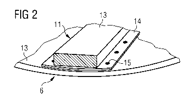
Figure 2 schematically shows part of an inventive generator
in a perspective view.
An embodiment of the present invention will now be described
with reference to Figure 1 and 2.
Figure 1 schematically shows a wind turbine 1. The wind tur-
bine 1 comprises a tower 2, a nacelle 3 and a hub 4. The na-
celle 3 is located on top of the tower 2. The hub 4 comprises

CA 02789825 2012-08-14
WO 2011/100987 PCT/EP2010/000961
a number of wind turbine blades 5. The hub 4 is mounted to
the nacelle 3. Moreover, the hub 4 is pivot-mounted such that
it is able to rotate about a rotation axis 9. A generator 6
is located inside the nacelle 3. The wind turbine 1 is a di-
5 rect drive wind turbine.
Figure 2 schematically shows part of an inventive generator 6
in a perspective view. The generator 6 comprises a magnet as-
sembly 11 and a base element 12. The magnet assembly 11 com-
prises at least one magnet 13 and a mounting plate 14. The
magnet 13 is connected to the mounting plate 14. For example,
a permanent magnet 13 is glued onto the mounting plate 14.
The mounting plate 14 is fastened to the base element 12 by
spot-welding. The weld points are designated by reference nu-
meral 15.
The magnet 13 can be a permanent magnet. Advantageously, a
non-magnetized magnet 13 is used, which is magnetized after
spot-welding the mounting plate 14 onto the base element 12.
This avoids disturbing attractive magnetic forces between the
elements. Moreover, the magnet 13 may be segmented. For exam-
ple, a number of permanent magnets 13 may be glued onto one
mounting plate 14.
The base element 12 may be part of the rotor of the generator
6 or it may be connected to the rotor of the generator 6.
Furthermore, the magnet 13 can be covered by a protective
cover. The protective cover may comprise stainless steel or a
plastic material. The protective cover provides a protection
of the magnet material against corrosion and other environ-
mental influences.
Instead of spot-welds also braze-welds or hard-soldering is
possible.
In summary, the present invention provides a simple and cost-
effective generator, especially for a wind turbine, and a

CA 02789825 2012-08-14
WO 2011/100987 PCT/EP2010/000961
6
simple and cost effective method for mounting of permanent
magnet assemblies to a generator rotor base.

Representative Drawing
A single figure which represents the drawing illustrating the invention.
Administrative Status

2024-08-01:As part of the Next Generation Patents (NGP) transition, the Canadian Patents Database (CPD) now contains a more detailed Event History, which replicates the Event Log of our new back-office solution.

Please note that "Inactive:" events refers to events no longer in use in our new back-office solution.

For a clearer understanding of the status of the application/patent presented on this page, the site Disclaimer , as well as the definitions for Patent , Event History , Maintenance Fee  and Payment History  should be consulted.

Event History

Description Date
Inactive: IPC expired 2022-01-01
Application Not Reinstated by Deadline 2017-07-04
Inactive: Dead - No reply to s.30(2) Rules requisition 2017-07-04
Deemed Abandoned - Failure to Respond to Maintenance Fee Notice 2017-02-16
Inactive: Abandoned - No reply to s.30(2) Rules requisition 2016-07-04
Inactive: S.30(2) Rules - Examiner requisition 2016-01-04
Inactive: Report - No QC 2015-12-17
Change of Address or Method of Correspondence Request Received 2015-01-15
Letter Sent 2014-10-17
Request for Examination Requirements Determined Compliant 2014-10-07
Request for Examination Received 2014-10-07
All Requirements for Examination Determined Compliant 2014-10-07
Inactive: Cover page published 2012-10-25
Application Received - PCT 2012-09-28
Inactive: Notice - National entry - No RFE 2012-09-28
Inactive: IPC assigned 2012-09-28
Inactive: First IPC assigned 2012-09-28
National Entry Requirements Determined Compliant 2012-08-14
Application Published (Open to Public Inspection) 2011-08-25

Abandonment History

Abandonment Date Reason Reinstatement Date
2017-02-16

Maintenance Fee

The last payment was received on 2016-01-13

Note : If the full payment has not been received on or before the date indicated, a further fee may be required which may be one of the following

  • the reinstatement fee;
  • the late payment fee; or
  • additional fee to reverse deemed expiry.

Please refer to the CIPO Patent Fees web page to see all current fee amounts.

Fee History

Fee Type Anniversary Year Due Date Paid Date
Basic national fee - standard 2012-08-14
MF (application, 2nd anniv.) - standard 02 2012-02-16 2012-08-14
MF (application, 3rd anniv.) - standard 03 2013-02-18 2013-01-17
MF (application, 4th anniv.) - standard 04 2014-02-17 2014-01-14
Request for examination - standard 2014-10-07
MF (application, 5th anniv.) - standard 05 2015-02-16 2015-01-22
MF (application, 6th anniv.) - standard 06 2016-02-16 2016-01-13
Owners on Record

Note: Records showing the ownership history in alphabetical order.

Current Owners on Record
SIEMENS AKTIENGESELLSCHAFT
Past Owners on Record
KURT ANDERSEN
Past Owners that do not appear in the "Owners on Record" listing will appear in other documentation within the application.
Documents

To view selected files, please enter reCAPTCHA code :


To view images, click a link in the Document Description column. To download the documents, select one or more checkboxes in the first column and then click the "Download Selected in PDF format (Zip Archive)" or the "Download Selected as Single PDF" button.

List of published and non-published patent-specific documents on the CPD .

If you have any difficulty accessing content, you can call the Client Service Centre at 1-866-997-1936 or send them an e-mail at CIPO Client Service Centre.


Document
Description 
Date
(yyyy-mm-dd) 
Number of pages   Size of Image (KB) 
Description 2012-08-14 6 220
Representative drawing 2012-08-14 1 6
Claims 2012-08-14 2 58
Abstract 2012-08-14 1 50
Drawings 2012-08-14 1 10
Cover Page 2012-10-25 1 32
Description 2012-08-15 8 232
Claims 2012-08-15 3 55
Notice of National Entry 2012-09-28 1 194
Acknowledgement of Request for Examination 2014-10-17 1 176
Courtesy - Abandonment Letter (R30(2)) 2016-08-15 1 166
Courtesy - Abandonment Letter (Maintenance Fee) 2017-03-30 1 176
PCT 2012-08-14 9 291
Correspondence 2015-01-15 2 64
Examiner Requisition 2016-01-04 3 236