Sélection de la langue

Search

Sommaire du brevet 2789825 

Énoncé de désistement de responsabilité concernant l'information provenant de tiers

Une partie des informations de ce site Web a été fournie par des sources externes. Le gouvernement du Canada n'assume aucune responsabilité concernant la précision, l'actualité ou la fiabilité des informations fournies par les sources externes. Les utilisateurs qui désirent employer cette information devraient consulter directement la source des informations. Le contenu fourni par les sources externes n'est pas assujetti aux exigences sur les langues officielles, la protection des renseignements personnels et l'accessibilité.

Disponibilité de l'Abrégé et des Revendications

L'apparition de différences dans le texte et l'image des Revendications et de l'Abrégé dépend du moment auquel le document est publié. Les textes des Revendications et de l'Abrégé sont affichés :

  • lorsque la demande peut être examinée par le public;
  • lorsque le brevet est émis (délivrance).
(12) Demande de brevet: (11) CA 2789825
(54) Titre français: PROCEDE D'ASSEMBLAGE D'UNE PARTIE D'UN GENERATEUR, GENERATEUR ET TURBINE D'EOLIENNE
(54) Titre anglais: METHOD FOR ASSEMBLING PART OF A GENERATOR, GENERATOR AND WIND TURBINE
Statut: Réputée abandonnée et au-delà du délai pour le rétablissement - en attente de la réponse à l’avis de communication rejetée
Données bibliographiques
Abrégés

Abrégé français

L'invention concerne un procédé d'assemblage d'une partie d'un générateur (6). Selon l'invention, un système (11) d'aimant comprenant au moins un aimant (13) et une plaque de montage (14) est attaché à un élément de base (12) par soudage (15) de la plaque de montage (14) à l'élément de base (12).


Abrégé anglais

A method for assembling part of a generator (6) is provided, wherein a magnet assembly (11) comprising at least one magnet (13) and a mounting plate (14) is fastened to a base element (12) by welding (15) the mounting plate (14) to the base element (12).

Revendications

Note : Les revendications sont présentées dans la langue officielle dans laquelle elles ont été soumises.


7
Claims
1. A method for assembling part of a generator (6),
wherein a magnet assembly (11) comprising at least one magnet
(13) and a mounting plate (14) is fastened to a base element
(12) by welding (15) the mounting plate (14) to the base ele-
ment (12).
2. The method as claimed in claim 2,
wherein the magnet assembly (11) is positioned and maintained
in the position before welding it to the base element (12).
3. The method as claimed in claim 1 or 2,
wherein a non-magnetized magnet (13) is used and the non-
magnetized magnet (13) is magnetised after welding the mount-
ing plate (14) to the base element (12).
4. The method as claimed in any of the claims 1 to 3,
wherein the mounting plate (14) is welded to the base element
(12) by means of an industrial robot.
5. The method as claimed in any of the claims 1 to 4,
wherein the mounting plate (14) is fastened to the base ele-
ment (12) by spot-welding (15) and/or braze-welding and/or
hard-soldering the mounting plate (14) to the base element
(12).
6. A generator (6) comprising a magnet assembly (11) and a
base element (12), the magnet assembly (11) comprising at
least one magnet (13) and a mounting plate (14),
wherein the mounting plate (14) is fastened to the base ele-
ment (12) by means of a number of welds (15).
7. The generator (6) as claimed in claim 6,
wherein the generator (6) comprises a rotor and the base ele-
ment (12) is part of the rotor or is connected to the rotor.
8. The generator (6) as claimed in claim 6 or 7,

8
wherein the magnet assembly (11) comprises at least one per-
manent magnet (13).
9. The generator (6) as claimed in any of the claims 6 to 8,
wherein the magnet (13) is segmented.
10. The generator (6) as claimed in any of the claims 7 to 9,
wherein the magnet (13) is covered by a protective cover.
11. The generator (6) as claimed in claim 10,
wherein the protective cover comprises stainless steel or a
plastic material.
12. The generator (6) as claimed in any of the claims 6 to
11,
wherein the generator (6) is a direct drive generator.
13. The generator (6) as claimed in any of the claims 6 to
12,
wherein the mounting plate (14) is fastened to the base ele-
ment (12) by means of a number of spot-welds (15) and/or
braze-welds and/or hard-soldering.
14. A wind turbine (1) comprising a generator (6) as claimed
in any of the claims 6 to 13.

Description

Note : Les descriptions sont présentées dans la langue officielle dans laquelle elles ont été soumises.

CA 02789825 2012-08-14
WO 2011/100987 PCT/EP2010/000961
1
Description
Method for assembling part of a generator, generator and wind
turbine
The present invention relates to a method for assembling part
of a generator. It further relates to a generator and to a
wind turbine.
Permanent magnet (PM) generator rotors for wind turbines are
known in the art. Here rods or segments of permanent magnet
material are mounted on the surface of a generator rotor on
some rotor base construction. The purpose of the magnets is
to induce current in generator stator coils which they pass
when the generator rotor is rotating. It is of most impor-
tance that the magnets are sufficiently secured to the said
rotor base construction as the distance between the magnets
and the stator coils often is only a few millimetres.
In EP 1 860 755 A2 a permanent magnet rotor arrangement is
provided. The arrangement includes a rotor having a radially
outer rim. A circumferential array of magnet carriers is a
fixed to the outer rim of the rotor by means of at least one
screw or bolt. The bolts or screws penetrate the rotor base
construction and are attached to a threaded portion of the
mounting plate.
One difficulty related to the former mentioned prior art is
that the process of fitting or mounting the permanent magnets
including their mounting plate to the rotor base is very time
consuming because numerous bolts and nuts are required in or-
der to hold and maintain the permanent magnet in the correct
position and to withstand the magnetic attractive forces that
act on the magnets once magnetized. The bolts have to be
mounted and tightened manually.
A first objective of the present invention is to provide an
advantageous method for assembling part of a generator. A

CA 02789825 2012-08-14
WO 2011/100987 PCT/EP2010/000961
2
second objective of the present invention is to provide an
advantageous generator. A third objective of the present in-
vention is to provide an advantageous wind turbine.
The first objective is solved by the method for assembling
part of a generator as claimed in claim 1. The second objec-
tive is solved by a generator as claimed in claim 6. The
third objective is solved by a wind turbine as claimed in
claim 14. The depending claims define further developments of
the invention.
In the inventive method for assembling part of a generator a
magnet assembly comprising at least one magnet and a mounting
plating is fastened to a base element by welding the mounting
plate to the base element. Using welding instead of bolts,
nuts or screws has the advantage, that it is simple, effec-
tive and cost-effective. For example, bolts, nuts or screws
have to be mounted and tightened manually, while the spot
welding can be performed by means of an industrial robot.
The magnet assembly may be positioned and maintained in the
position before welding it to the base element. The base ele-
ment may be, for example, part of a rotor of the generator.
Preferably, a non-magnetized magnet may be used. The non-
magnetized magnet can be magnetized after welding the mount-
ing plate to the base element. Using a non-magnetized magnet
is advantageous, because during the fastening process no at-
tractive magnetic forces are acting between the magnet and
the means for fastening.
Preferably, the mounting plate is welded to the base element
by means of an industrial robot. Such industrial robot can
perform multiple of the steps required for the mounting proc-
ess. For example, the industrial robot may pick up a prein-
stalled magnet assembly from storage and may position it in a
correct position on the generator base element. The base ele-
ment may be, for example, a generator rotor base construc-

CA 02789825 2012-08-14
WO 2011/100987 PCT/EP2010/000961
3
tion. Moreover, the industrial robot may maintain the posi-
tion during fastening without the need of other holding
means. Furthermore, the industrial robot can fasten the mag-
net assembly to the base element by welding the mounting
plate to the base construction at a plurality of welding
points, especially spot welding points, along the mounting
plate construction.
Preferably, the mounting plate may be fastened to the base
element by spot-welding the mounting plate to the base ele-
ment. Braze-welding and/or hard-soldering is also possible.
As to the number of welding points it must be ensured that
enough points are made so that the permanent magnet assembly
will maintain its position both during mounting and during
operation. The permanent magnet assembly has to be able to
withstand any magnetic attractive forces that may occur once
the magnet is magnetized.
Furthermore, by the present invention it is ensured that at
least the process of fastening the permanent magnet assembly
to the base construction is shortened in time as the time
consuming process of tightening nuts to specific moment-level
is replaced by a speedy industrial robot spot welding proc-
ess.
The inventive generator comprises a magnet assembly and a
base element. The magnet assembly comprises at least one mag-
net and a mounting plate. The mounting plate is fastened to
the base element by means of a number of welds, preferably
spot-welds. For example, the generator may comprise a rotor.
The base element may be part of the rotor or the base element
may be connected to the rotor.
The magnet assembly can comprise at least one permanent mag-
net. Moreover, the magnet can be segmented. This allows for
an easy assembling. For example, a number of permanent mag-
nets may be connected to the same mounting plate.

CA 02789825 2012-08-14
WO 2011/100987 PCT/EP2010/000961
4
Advantageously, the magnet can be covered by a protective
cover. The protective cover can comprise stainless steel or a
plastic material. For example, the protective cover may con-
sist of stainless steel or a plastic material. The protective
cover provides a protection of the magnet or of the magnet
material against corrosion and other environmental influ-
ences.
Generally, the generator may be a direct drive generator.
The mounting plate may be fastened to the base element by
means of a number of spot-welds and/or braze-welds and/or
hard-soldering.
The inventive wind turbine comprises an inventive generator,
as previously described. The inventive wind turbine has the
same advantages as the inventive generator has.
In the context of the present invention welding comprises
spot-welding, braze-welding and soldering, especially hard-
soldering.
Further features, properties and advantages of the present
invention will become clear from the following description of
an embodiment in conjunction with the accompanying drawings.
Figure 1 schematically shows a wind turbine.
Figure 2 schematically shows part of an inventive generator
in a perspective view.
An embodiment of the present invention will now be described
with reference to Figure 1 and 2.
Figure 1 schematically shows a wind turbine 1. The wind tur-
bine 1 comprises a tower 2, a nacelle 3 and a hub 4. The na-
celle 3 is located on top of the tower 2. The hub 4 comprises

CA 02789825 2012-08-14
WO 2011/100987 PCT/EP2010/000961
a number of wind turbine blades 5. The hub 4 is mounted to
the nacelle 3. Moreover, the hub 4 is pivot-mounted such that
it is able to rotate about a rotation axis 9. A generator 6
is located inside the nacelle 3. The wind turbine 1 is a di-
5 rect drive wind turbine.
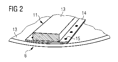
Figure 2 schematically shows part of an inventive generator 6
in a perspective view. The generator 6 comprises a magnet as-
sembly 11 and a base element 12. The magnet assembly 11 com-
prises at least one magnet 13 and a mounting plate 14. The
magnet 13 is connected to the mounting plate 14. For example,
a permanent magnet 13 is glued onto the mounting plate 14.
The mounting plate 14 is fastened to the base element 12 by
spot-welding. The weld points are designated by reference nu-
meral 15.
The magnet 13 can be a permanent magnet. Advantageously, a
non-magnetized magnet 13 is used, which is magnetized after
spot-welding the mounting plate 14 onto the base element 12.
This avoids disturbing attractive magnetic forces between the
elements. Moreover, the magnet 13 may be segmented. For exam-
ple, a number of permanent magnets 13 may be glued onto one
mounting plate 14.
The base element 12 may be part of the rotor of the generator
6 or it may be connected to the rotor of the generator 6.
Furthermore, the magnet 13 can be covered by a protective
cover. The protective cover may comprise stainless steel or a
plastic material. The protective cover provides a protection
of the magnet material against corrosion and other environ-
mental influences.
Instead of spot-welds also braze-welds or hard-soldering is
possible.
In summary, the present invention provides a simple and cost-
effective generator, especially for a wind turbine, and a

CA 02789825 2012-08-14
WO 2011/100987 PCT/EP2010/000961
6
simple and cost effective method for mounting of permanent
magnet assemblies to a generator rotor base.

Dessin représentatif
Une figure unique qui représente un dessin illustrant l'invention.
États administratifs

2024-08-01 : Dans le cadre de la transition vers les Brevets de nouvelle génération (BNG), la base de données sur les brevets canadiens (BDBC) contient désormais un Historique d'événement plus détaillé, qui reproduit le Journal des événements de notre nouvelle solution interne.

Veuillez noter que les événements débutant par « Inactive : » se réfèrent à des événements qui ne sont plus utilisés dans notre nouvelle solution interne.

Pour une meilleure compréhension de l'état de la demande ou brevet qui figure sur cette page, la rubrique Mise en garde , et les descriptions de Brevet , Historique d'événement , Taxes périodiques et Historique des paiements devraient être consultées.

Historique d'événement

Description Date
Inactive : CIB expirée 2022-01-01
Demande non rétablie avant l'échéance 2017-07-04
Inactive : Morte - Aucune rép. dem. par.30(2) Règles 2017-07-04
Réputée abandonnée - omission de répondre à un avis sur les taxes pour le maintien en état 2017-02-16
Inactive : Abandon. - Aucune rép dem par.30(2) Règles 2016-07-04
Inactive : Dem. de l'examinateur par.30(2) Règles 2016-01-04
Inactive : Rapport - Aucun CQ 2015-12-17
Requête pour le changement d'adresse ou de mode de correspondance reçue 2015-01-15
Lettre envoyée 2014-10-17
Exigences pour une requête d'examen - jugée conforme 2014-10-07
Requête d'examen reçue 2014-10-07
Toutes les exigences pour l'examen - jugée conforme 2014-10-07
Inactive : Page couverture publiée 2012-10-25
Demande reçue - PCT 2012-09-28
Inactive : Notice - Entrée phase nat. - Pas de RE 2012-09-28
Inactive : CIB attribuée 2012-09-28
Inactive : CIB en 1re position 2012-09-28
Exigences pour l'entrée dans la phase nationale - jugée conforme 2012-08-14
Demande publiée (accessible au public) 2011-08-25

Historique d'abandonnement

Date d'abandonnement Raison Date de rétablissement
2017-02-16

Taxes périodiques

Le dernier paiement a été reçu le 2016-01-13

Avis : Si le paiement en totalité n'a pas été reçu au plus tard à la date indiquée, une taxe supplémentaire peut être imposée, soit une des taxes suivantes :

  • taxe de rétablissement ;
  • taxe pour paiement en souffrance ; ou
  • taxe additionnelle pour le renversement d'une péremption réputée.

Veuillez vous référer à la page web des taxes sur les brevets de l'OPIC pour voir tous les montants actuels des taxes.

Historique des taxes

Type de taxes Anniversaire Échéance Date payée
Taxe nationale de base - générale 2012-08-14
TM (demande, 2e anniv.) - générale 02 2012-02-16 2012-08-14
TM (demande, 3e anniv.) - générale 03 2013-02-18 2013-01-17
TM (demande, 4e anniv.) - générale 04 2014-02-17 2014-01-14
Requête d'examen - générale 2014-10-07
TM (demande, 5e anniv.) - générale 05 2015-02-16 2015-01-22
TM (demande, 6e anniv.) - générale 06 2016-02-16 2016-01-13
Titulaires au dossier

Les titulaires actuels et antérieures au dossier sont affichés en ordre alphabétique.

Titulaires actuels au dossier
SIEMENS AKTIENGESELLSCHAFT
Titulaires antérieures au dossier
KURT ANDERSEN
Les propriétaires antérieurs qui ne figurent pas dans la liste des « Propriétaires au dossier » apparaîtront dans d'autres documents au dossier.
Documents

Pour visionner les fichiers sélectionnés, entrer le code reCAPTCHA :


Pour visualiser une image, cliquer sur un lien dans la colonne description du document. Pour télécharger l'image (les images), cliquer l'une ou plusieurs cases à cocher dans la première colonne et ensuite cliquer sur le bouton "Télécharger sélection en format PDF (archive Zip)" ou le bouton "Télécharger sélection (en un fichier PDF fusionné)".

Liste des documents de brevet publiés et non publiés sur la BDBC .

Si vous avez des difficultés à accéder au contenu, veuillez communiquer avec le Centre de services à la clientèle au 1-866-997-1936, ou envoyer un courriel au Centre de service à la clientèle de l'OPIC.


Description du
Document 
Date
(aaaa-mm-jj) 
Nombre de pages   Taille de l'image (Ko) 
Description 2012-08-14 6 220
Dessin représentatif 2012-08-14 1 6
Revendications 2012-08-14 2 58
Abrégé 2012-08-14 1 50
Dessins 2012-08-14 1 10
Page couverture 2012-10-25 1 32
Description 2012-08-15 8 232
Revendications 2012-08-15 3 55
Avis d'entree dans la phase nationale 2012-09-28 1 194
Accusé de réception de la requête d'examen 2014-10-17 1 176
Courtoisie - Lettre d'abandon (R30(2)) 2016-08-15 1 166
Courtoisie - Lettre d'abandon (taxe de maintien en état) 2017-03-30 1 176
PCT 2012-08-14 9 291
Correspondance 2015-01-15 2 64
Demande de l'examinateur 2016-01-04 3 236