Note: Descriptions are shown in the official language in which they were submitted.
CA 02790010 2012-09-12
DENTAL PROSTHESIS AND MANUFACTURING METHOD THEREOF
[Technical Field]
The present invention relates to a dental prosthesis, and
more particularly, to a screw-engagement type dental
prosthesis which enables non-preparation of a natural tooth
(abutment tooth) because it is manufactured by division into
two or three pieces, which can be simply installed, and in
which the occlusal pressure can be uniformly dispersed. Also,
the present invention relates to a method of casting a screw-
engagement type dental prosthesis by using a bolt made of
carbon or ceramics.
[Background Art]
In general, prosthesis is performed when a tooth is
damaged or missing due to an oral disease. The prosthesis is
to wrap a weak tooth or to restore a missing portion of a
tooth. Among the prosthesis methods, a crown bridge is used
most generally, which employs the natural tooth positioned on
either side of the missing tooth as abutment teeth. As shown
in FIG. 1, the crown bridge positions an artificial tooth 12
at a site where a missing tooth was positioned, and prepares a
part of the abutment tooth 10, and then securely wraps a crown
over the abutment tooth 10.
However, such a crown bridge has disadvantages that it
CA 02790010 2012-09-12
2
causes a pain to a patient at the time of the preparation
(prep) of the tooth, raises a secondary problem such as
denaturalization of the dental pulp due to an increase of the
prepared amount of the tooth structure of the abutment tooth,
and induces exposure of the tooth pulp and hypersensitivity
reaction, and the like. Also, since the occlusal surfaces of
the abutment teeth are prepared, it is not possible to
naturally restore the occlusal surfaces as usual.
Meanwhile, an inlay-type prosthesis as shown in FIG. 2
may be employed to prevent such disadvantages. The inlay
prosthesis is to supportingly fit an artificial tooth at a
site of a missing tooth, in such a manner that the inlay 22
secured to the side abutment tooth, is press-fit into a recess
groove 21 of the artificial tooth 20. After drilling a hole at
the abutment tooth (see numeral 10 of FIG. 10) so as to insert
protrusions 24 of the inlay 22 thereto, the inlay 22 is
inserted into the hole and bonded (cementing) from the upper
side so that an insertion portion 27 can be inserted into the
recess groove 21 of the artificial tooth 20. The inlay-type
prosthesis can be regarded as prosthesis of a type of
preparing the abutment tooth in a small amount because there
is a small necessity of preparing the abutment tooth 10.
However, such a conventional inlay-type prosthesis has a
disadvantage that holes should be precisely drilled at the
abutment tooth 10 to securely fix the inlay 22 to the abutment
CA 02790010 2012-09-12
3
tooth 10. In other words, when the precision of the hole
drilled at the abutment tooth is reduced, abnormal occlusal
occurs thereby causing inconvenience of a patient.
In contrast to the inlay-type prosthesis, as shown in FIG.
3, there has been recently known a press-fitting type
prosthesis. The press-fitting type prosthesis is constructed
such that a plurality of support portions 33 is provided to
wrap the abutment tooth 38, and a male body 37 formed at the
support portion 33 is press-fit to a female body 36 of the
artificial tooth 35.
The support portion 33 can be provided in plural number,
it required, so that it can be easily assembled. However, the
conventional press-fitting type prosthesis entails a merit
that it has good occlusal and reduces pains of a patient since
the abutment tooth 38 is not prepared. Nevertheless, there
occurs a disadvantage that the bonding force is reduced
because it is of a press-fitting type. Also, the artificial
tooth 35 is to be inserted into two abutment teeth in a state
where the support portion 33 is attached to the abutment tooth
38 and maintained in the course of the assembly and operation
of the prosthesis. Thus, if the male body 37 and the female
body 36 are not minutely mated with each other, there could be
caused a disadvantage that abnormal occlusal occurs or
deformation of the prosthesis occurs when it is used for a
long time because it cannot endure the occlusal pressure.
CA 02790010 2012-09-12
4
[Disclosure]
[Technical Problem)
Accordingly, the present invention has been made in an
effort to solve the above aforementioned problems, and an
object of the present invention is to provide a screw-
engagement type dental prosthesis, which can be simply
installed into two or three pieces without any preparation of
the abutment tooth and in which the occlusal pressure can be
uniformly dispersed, and a manufacturing method thereof.
Furthermore, another object of the present invention is to
provide a screw-engagement type dental prosthesis, which
additionally have a semi-conical maintaining portion through a
small preparation of adjacent surfaces of both abutment teeth,
and which can be simply installed into two pieces and
uniformly disperse the occlusal pressure, and a manufacturing
method thereof.
Moreover, a further object of the present invention is to
provide a dental prosthesis, which can be used even in a
condition where it is difficult to use bolts by substituting
for an engagement force of bolts and drastically reducing the
degree of difficulty in work and the number of processes, and
a manufacturing method thereof.
[Technical Solution)
CA 02790010 2012-09-12
To achieve the above object, the present invention
provides a dental prosthesis for restoring a missing tooth,
comprising: a keeper disposed to wrap an abutment tooth of one
side from a lingual side; a base disposed to wrap an abutment
5 tooth of other side and the keeper, and a body acting as an
artificial tooth and engaged with the keeper and the base by
means of a screw, and disposed to wrap the abutment tooth of
one side or the abutment tooth of the other side in a
direction opposite to a direction in which the keeper wraps.
Also, according to the dental prosthesis of the present
invention, the base is disposed in a direction in which the
keeper wraps the abutment tooth of the other side.
In addition, the base is provided with a base rear wall
for supporting a rear wall of the body.
Moreover, the keeper includes a keeper bottom portion
adapted to be seated on the missing tooth portion formed by
both abutment teeth, and the base further includes a base
bottom portion for wrapping the keeper bottom portion.
Furthermore, the base bottom portion is formed with an
insertion recess for inserting the keeper bottom portion
thereto, the insertion recess having a screw hole for the
screw engagement drilled therein.
In addition, the keeper bottom portion is further formed
with a keeper groove, and the insertion recess is formed with
an insertion protrusion to correspond to the keeper groove.
CA 02790010 2012-09-12
6
According to another aspect of the present invention,
there is provided a casting method for manufacturing a dental
prosthesis, wherein a step of constructing a duplication model
for casting a base and a body includes a first step of
inserting a titanium bolt into a screw hole for the screw
engagement, a second step of performing impression, a third
step of removing the titanium bolt after curing, a fourth step
of inserting a carbon or ceramic bolt into a place from which
the titanium bolt is removed, and a fifth step of casting by
means of engraving and filling.
Preferably the fifth step includes a step of obtaining a
duplicating model by injecting filling material and a step of
casting by means of engraving and filling.
In addition, the second step includes injecting impression
material to an injection indicating portion, as the titanium
bolt for the duplication is formed with the injection
indicating portion for the duplication material, and the
fourth step includes inserting the ceramic bolt to a position
indicating portion, as the ceramic bolt is formed with the
position indicating portion and a position determining portion.
Also, according to still another aspect of the present
invention, there is provided a casting method for
manufacturing a dental prosthesis, wherein a step of
constructing a duplication model for casting a base and a body
includes a first step of inserting a titanium bolt into a
CA 02790010 2012-09-12
7
screw hole for the screw engagement, a second step of
performing impression, a third step of removing the titanium
bolt after curing, a fourth step of performing a wax work
after obtaining a refractory model by injecting filling
material for the casting, and a fifth step of casting by
filling.
In addition, a sub-step of inserting a correction wire
into a place, from which the titanium bolt is removed, is
performed between the third step and the fourth step.
Furthermore, a female screw drilled at the dental
prosthesis is formed by casting after obtaining a carbon bolt
or a ceramic bolt by turning and grinding the compressed
carbon and the compressed and sintered ceramic.
To achieve the above object, in case of a molar tooth
portion of FIG. 24, the present invention provides a dental
prosthesis for restoring a missing tooth, comprising: a keeper
disposed to wrap an abutment tooth of one side from a lingual
side and a buccal side; and a body disposed to wrap an
abutment tooth of the other side from the lingual side and the
buccal side, the body acting as an artificial tooth and
engaged with the keeper by means of a screw.
In case of a front tooth portion of FIG. 27, the present
invention provides a dental prosthesis for restoring a missing
tooth, comprising: a keeper disposed to simultaneously wrap an
abutment tooth of one side at adjacent surfaces of a lingual
CA 02790010 2012-09-12
8
side and a lip side; and a body disposed to wrap an abutment
tooth of the other side at adjacent surfaces of the lingual
side and the lip side, the body acting as an artificial tooth
and engaged with the keeper by means of a screw.
As another embodiment of a molar tooth portion of FIG. 33,
in case where an abutment tooth of one side used as a keeper
is the rearmost tooth, the present invention provides a dental
prosthesis for restoring a missing tooth, comprising: a keeper
disposed to simultaneously wrap an abutment tooth of one side
from a lingual side, a buccal side and a distal center side;
and a body disposed to simultaneously wrap an abutment tooth
of the other side from the lingual side and the buccal side,
the body acting as an artificial tooth and engaged with the
keeper by means of a screw.
The keeper includes a keeper bottom portion seated on a
missing tooth portion located between the abutment teeth of
both sides, and the body includes a body bottom portion
adapted to wrap the keeper bottom portion while acting as an
artificial tooth. The body bottom portion has an insertion
recess for inserting the keeper bottom portion thereinto, and
a screw hole for a screw-engagement is drilled at the
insertion recess. The keeper bottom portion additionally
includes a keeper groove and the insertion recess of the body
includes an insertion protrusion corresponding to the keeper
groove.
CA 02790010 2012-09-12
9
In another aspect of the present invention, the present
invention provides a manufacturing method of a dental
prosthesis comprising a step of constructing a duplication
model for casting a body, the duplication model constructing
step including: a first step of inserting a titanium bolt into
a screw hole drilled in a keeper for screw engagement, a
second step of performing impression, a third step of removing
the titanium bolt, a stone model and the previously
manufactured keeper after curing, a fourth step of inserting a
carbon or ceramic bolt into a place from which the titanium
bolt is removed, and a fifth step of casting by means of
engraving and filling.
Preferably, the fifth step includes a step of obtaining a
duplication model by injecting filling material and a step of
performing casting by means of engraving and filling.
Here, since the titanium bolt has an injection indicating
portion for guiding injection of duplication material, in the
second step, impression material is injected up to the
injection indicating portion. Moreover, since the ceramic bolt
has a position indicating portion, in the fourth step, the
bolt is inserted up to the position indicating portion.
Furthermore, a female is drilled at the dental prosthesis
according to a casting method using a carbon bolt and a
ceramic bolt, which are respectively obtained by turning
compression-molded carbon and compression-molded and sintered
CA 02790010 2012-09-12
ceramic.
In addition, to achieve the above objects, in case of a
molar tooth portion of FIG. 34, the present invention provides
a dental prosthesis for restoring a missing tooth,
5 comprising: a keeper disposed to wrap an abutment tooth of one
side from a lingual side and a buccal side; a body disposed to
wrap an abutment tooth of the other side from the lingual side
and the buccal side, the body acting as an artificial tooth
and engaged with the keeper by means of a screw; and thin and
10 semi-conical keys disposed on the inner inclination surfaces
of the keeper and the body.
In case of a front tooth portion of FIG. 36, the present
invention provides a dental prosthesis for restoring a missing
tooth, comprising: a keeper disposed to simultaneously wrap an
abutment tooth of one side at adjacent surfaces of a lingual
side and a lip side; a body disposed to wrap an abutment tooth
of the other side at adjacent surfaces of the lingual side and
the lip side, the body acting as an artificial tooth and
engaged with the keeper by means of a screw; and thin and
semi-conical keys disposed on the inner inclination surfaces
of the keeper and the body.
As another embodiment of a molar tooth portion of FIG. 39,
in case where an abutment tooth of one side used as a keeper
is the rearmost tooth, the present invention provides a dental
prosthesis for restoring a missing tooth, comprising: a keeper
CA 02790010 2012-09-12
11
disposed to simultaneously wrap an abutment tooth of one side
from a lingual side, a buccal side and a distal center side;
and a body disposed to simultaneously wrap an abutment tooth
of the other side from the lingual side and the buccal side,
the body acting as an artificial tooth and engaged with the
keeper by means of a screw. The keeper includes a keeper
bottom portion seated on a missing tooth portion located
between the abutment teeth of both sides, and the body
includes a body bottom portion adapted to wrap the keeper
bottom portion while acting as an artificial tooth. The body
bottom portion has an insertion recess for inserting the
keeper bottom portion thereinto, and a screw hole for a screw-
engagement is drilled at the insertion recess. The keeper
bottom portion additionally includes a keeper groove and the
insertion recess of the body includes an insertion protrusion
corresponding to the keeper groove.
Furthermore, to achieve the above objects, in case of a
molar tooth portion of FIG. 41, the present invention provides
a dental prosthesis for restoring a missing tooth,
comprising: a keeper disposed to wrap an abutment tooth of one
side from a lingual side and a buccal side, the keeper having
a keeper male, which is an engagement portion; a body disposed
to wrap an abutment tooth of the other side from the lingual
side and the buccal side, the body acting as an artificial
tooth and having a body female engaged with the keeper male
CA 02790010 2012-09-12
12
through friction resistance. In FIG. 40, the dental prosthesis
further comprises thin and semi-conical keys disposed on the
inner inclination surfaces of the keeper and the body. In case
of a dental prosthesis with non-preparation shown in FIG. 41,
the keys are not formed on the inner inclination surfaces of
the keeper and the body.
As another embodiment of a molar tooth portion of FIG. 48,
in case where an abutment tooth of one side used as a keeper
is the rearmost tooth, the present invention provides a dental
prosthesis for restoring a missing tooth, comprising: a keeper
disposed to simultaneously wrap an abutment tooth of one side
from a lingual side, a buccal side and a distal center side;
and a body disposed to simultaneously wrap an abutment tooth
of the other side from the lingual side and the buccal side,
the body acting as an artificial tooth and engaged with the
keeper by means of a screw. The keeper includes a keeper
bottom portion seated on a missing tooth portion located
between the abutment teeth of both sides, and the body
includes a body bottom portion adapted to wrap the keeper
bottom portion while acting as an artificial tooth. The body
bottom portion has an insertion recess for inserting the
keeper bottom portion thereinto, and the keeper male for the
friction resistance may be formed on the inner portion of the
insertion recess. Moreover, the keeper bottom portion
additionally includes a keeper groove and the insertion recess
CA 02790010 2012-09-12
13
of the body includes an insertion protrusion corresponding to
the keeper groove.
[Advantageous Effects)
As described above, according to the dental prosthesis of
the present invention, it is not necessary to prepare the
abutment tooth so that the pains of a patient and occurrence
of a secondary problem can be minimized, and it can be simply
installed, and it is possible to disperse the occlusal
pressure uniformly so that the dental operation can be
facilitated. Also, it is possible to drill an accurate screw
engagement hole by using a specially devised titanium bolt or
a ceramic bolt.
Furthermore, the dental prosthesis according to the
present invention can reinforce a maintaining force thereof
since the thin and semi-conical keys disposed on the inner
inclination surfaces of the keeper and the body, minimize
pains of a patient and secondary problems by providing an
aesthetic dental prosthesis, be simply installed, and
uniformly disperse occlusal pressure. Particularly, in case of
the front tooth portion, since an aesthetic aspect is as
important as a function, the present invention can more
improve the aesthetic aspect and provide an excellent function
by minimizing the maintaining portion of the inner inclination
surface of the lip side of the front tooth.
CA 02790010 2012-09-12
14
Moreover, since the dental prosthesis, which has no
preparation or has the thin and semi-conical key formed on the
inner inclination surface of the body, applies not a bolt
engagement method but a principle to provide the maintaining
force of friction resistance of a double-pipe prosthesis, the
present invention can secure necessary maintaining force
through the friction resistance of the keeper male and the
body female, reduce the number of work processes requiring
high-grade skills, and drastically reduce manufacturing costs
as it does not sue various bolts. Accordingly, the dental
prosthesis according to the present invention can be provided
inexpensively by reducing necessary time period and expenses
but enhancing productivity, and hence, reduce a patient's
financial burden.
[Description of Drawings]
FIG. 1 is a construction view of a conventional bridge
prosthesis.
FIG. 2 is a construction view of a conventional inlay-type
prosthesis.
FIG. 3 is a construction view of a conventional press
fitting type prosthesis.
FIG. 4 is a whole perspective view of the present
invention.
CA 02790010 2012-09-12
FIG. 5 is an assembly view of an upper surface of a
missing tooth portion of the present invention.
FIG. 6 is a front view of a buccal side of a keeper of the
present invention.
5 FIG. 7 is a front view of a buccal side of a base of the
present invention.
FIG. 8 is a rear view of a lingual side of a body of the
present invention.
FIG. 9 is an assembly view of an upper portion of the two
10 missing tooth portions of the present invention.
FIG. 10 is an assembly view of four missing front tooth
portions of the present invention.
FIG. 11 is a view explaining the attachment of a plastic
keeper for performing a primary casting according to the
15 present invention.
FIG. 12 is a view explaining the position determining work
of a ceramic bolt for forming a female screw of a keeper for
performing the primary casting according to the present
invention.
FIG. 13 is a top plan view showing bottom shapes of
several keepers.
FIG. 14 is a view explaining a duplication model work for
the secondary casting.
FIG. 15 is a view explaining a duplication model work for
the tertiary casting.
CA 02790010 2012-09-12
16
FIG. 16 is a side view of a bolt for the duplication and
casting.
FIG. 17 is a view explaining a bottom portion of a keeper
according to second embodiment of the present invention.
FIG. 18 is a side view of a bolt for the duplication and
casting of third embodiment of the present invention.
FIG. 19 is a view explaining a duplication model work for
the secondary casting according to fourth embodiment of the
present invention.
FIG. 20 is a side view forming female screws at a keeper
hole, a base hole, and a body hole of the present invention.
FIG. 21 is a side view forming female screws at a keeper
hole and a base hole of the present invention.
FIG. 22 is a side view forming a female screw at a keeper
hole of the present invention.
FIG. 23 is an entire perspective view of fifth embodiment
of the present invention.
FIG. 24 is an entire perspective view of a molar tooth
portion of the present invention using a dental prosthesis
divided into two pieces.
FIG. 25 (a) is an assembly view of an upper surface of a
missing tooth portion of the present invention using the
dental prosthesis divided into two pieces, and (b) is a cross-
sectional view of a main portion of a body and an occlusal
portion viewed from a portion engaged with a keeper outer wall.
CA 02790010 2012-09-12
17
FIG. 26 is a front view of a buccal side of a keeper of
the present invention using a dental prosthesis divided into
two pieces.
FIG. 27 (a) is an assembly view of a front tooth portion
of the present invention using the dental prosthesis divided
into two pieces, and (b) is a view of a body lingual side of
the front tooth portion.
FIG. 28 is an assembly view of an upper surface of the two
missing tooth portions of the present invention using the
dental prosthesis divided into two pieces.
FIG. 29 is a view explaining the attachment of a plastic
keeper for performing a primary casting according to the
present invention using the dental prosthesis divided into two
pieces.
FIG. 30 is a view explaining the position determining work
of a ceramic bolt for forming a female screw of the keeper by
performing the primary casting according to the present
invention using the dental prosthesis divided into two pieces.
FIG. 31 is a view explaining a duplication model work for
the secondary casting according to the present invention using
the dental prosthesis divided into two pieces.
FIG. 32 (a) and (b) are views explaining a keeper bottom
portion and a body bottom portion according to a seventh
embodiment of the present invention using the dental
prosthesis divided into two pieces.
CA 02790010 2012-09-12
18
FIG. 33 is a view of another example of the molar tooth
portion using the dental prosthesis divided into two pieces.
FIG. 34 is an entire perspective view of the molar tooth
portion using a maintaining portion and a key.
FIG. 35 (a) is an assembly view of an upper surface of a
missing tooth portion of the present invention using the
maintaining portion and the key, and (b) is a cross-sectional
view of a main portion of a body and an occlusal portion
viewed from a portion engaged with a keeper outer wall.
FIG. 36 (a) is an assembly view of a front tooth portion
of the present invention using the maintaining portion and the
key, (b) is a plan view, in section, of the front tooth
portion, and (c) is a view of a lingual side of a body of the
front tooth portion.
FIG. 37 is an assembly view of an upper surface of two
missing tooth portions of the present invention using the
maintaining portion and the key.
FIG. 38 (a) is a view explaining a keeper bottom portion
according to a tenth embodiment of the present invention using
the maintaining portion and the key, and (b) is a view
explaining a body bottom portion.
FIG. 39 is a view of another embodiment of a molar tooth
portion of the present invention using the maintaining portion
and the key.
FIG. 40 is an entire perspective view of a molar tooth
CA 02790010 2012-09-12
19
portion of the present invention using a keeper male and a
body female.
FIG. 41 is an entire perspective view of a molar tooth
portion with non-preparation according to the present
invention using the keeper male and the body female.
FIG. 42 is a front view of a buccal side of a keeper using
the keeper male and the body female.
FIG. 43 (a) is an assembly view of a front tooth portion
according to the present invention using the keeper male and
the body female, (b) is a view of a key-forming portion viewed
from a lingual side cut face, and (c) is a view of a lingual
side of a body of the front tooth portion.
FIG. 44 (a) is an assembly view of a front tooth portion
with non-preparation according to the present invention using
the keeper male and the body female, (b) is an assembly view
of a tooth with non-preparation viewed from the lingual side
cut face, and (c) is a view of a lingual side of a body of the
front tooth portion with non-preparation type.
FIG. 45 (a) is a view of an upper portion showing forms of
various keeper bottom portions according to the present
invention using the keeper male and the body female, and (b)
is a side view showing a keeper male form.
FIG. 46 is a sectional view of various keeper males for
increasing a friction force according to the present invention
using the keeper male and the body female.
CA 02790010 2012-09-12
FIG. 47 (a) is an explanation view of a keeper bottom
portion according to a thirteenth embodiment of the present
invention using the keeper male and the body female, and (b)
is an explanation view of a body bottom portion.
5 FIG. 48 is a view showing another embodiment of the molar
tooth portion according to the present invention using the
keeper male and the body female.
(Mode for invention)
10 Hereinafter, the preferred embodiments of the present
invention will be described in detail with reference to the
appended drawings.
In the present invention, FIGS. 1 to 23 illustrate a
dental prosthesis divided into three pieces, wherein FIG. 4 is
15 an entire perspective view of the present invention, FIG.5 is
an assembly view of an upper surface of a missing tooth
portion of the present invention, FIGS. 6, 7, and 8 are views
showing a keeper, a base, and a body of the present invention,
FIG. 9 is an assembly view of an upper portion of the two
20 missing tooth portions of the present invention, FIG. 10 is an
assembly view of four missing front tooth portions of the
present invention, FIGS. 11 and 15 are views explaining a
manufacturing method of the present invention, FIG. 16 is a
side view of a bolt for the duplication and casting.
FIGS. 24 to 48 illustrate a dental prosthesis divided into
CA 02790010 2012-09-12
21
two pieces, wherein FIG. 24 is an entire perspective view of a
molar tooth portion of the present invention, FIG. 25 is an
assembly view of an upper surface of a missing tooth portion,
and FIG. 26 is a view of a keeper of the present invention.
FIG. 27 is an assembly view of a front tooth portion, FIG.
28 is an assembly view of an upper surface of the two missing
tooth portions of the present invention, and FIGS. 29 to 31
are views for explaining manufacturing method of the present
invention, and FIG. 33 is a view of another example of the
molar tooth portion.
FIG. 34 is an entire perspective view of a molar tooth
portion using a prosthesis having semi-conical keys 180 and
380, and FIG. 35 is an assembly view of an upper portion of
one missing molar tooth portion. FIG. 36 is an assembly view
of a front tooth portion using the prosthesis having the semi-
conical keys 180 and 380, FIG. 37 is an assembly view of an
upper portion of two missing molar tooth portions, and FIG. 39
is a view showing another embodiment of the molar tooth
portion.
FIG. 40 is an entire perspective view of a molar tooth
portion using a keeper male 101 and a body female 301, FIG. 41
is an entire perspective view of a molar tooth portion with
non-preparation, and FIG. 42 is a view of a keeper according
to the present invention.
FIG. 43 (a) is an assembly view of a front tooth portion
CA 02790010 2012-09-12
22 '
using the keeper male 101 and the body female 301, (b) is a
view of a key-forming portion viewed from a lingual side cut
face, and (c) is a view of a lingual side of a body of the
front tooth portion using a key. FIG. 44 (a) is an assembly
view of a front tooth portion with non-preparation using the
keeper male 101 and the body female 301, (b) shows a non-
preparation tooth state viewed from the lingual side cut face,
and (c) is a view of a lingual side of a body of the front
tooth portion with non-preparation type.
FIG. 45 (a) is a view of an upper portion showing forms of
various keeper bottom portions using the keeper male 101 and
the body female 301, (b) is a side view showing a keeper male
form, and FIG. 46 is a sectional view of various keeper males
101 for increasing a friction force. FIG. 47 (a) is an
explanation view of a keeper bottom portion according to a
thirteenth embodiment of the present invention, FIG. 47b is an
explanation view of a body bottom portion according to the
thirteenth embodiment, and FIG. 48 is a view showing another
embodiment of the molar tooth portion using the keeper male
101 and the body female 301..
In the drawings, dispensable portions are omitted to
clarify the technical gist of the present invention, and the
omitted portions are the same as those shown in the
conventional dental prosthesis and manufacturing method
thereof.
CA 02790010 2012-09-12
23
Hereinafter, the present invention will be described in
more detail with reference to the concrete embodiments.
(First embodiment)
Hereinafter the screw-engagement type dental prosthesis
with non-preparation according to a first embodiment of the
present invention will be described with reference to FIGs. 4
through 8.
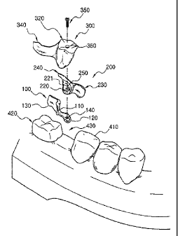
As shown in FIG. 4, the dental prosthesis of the present
invention comprises a keeper 100 wrapping an abutment tooth
410 of one side from a lingual side, a base 200 wrapping an
abutment tooth 420 of the other side from the lingual side,
and a body 300 inserted into a missing tooth portion 430 and
wrapping the abutment tooth 410 from a buccal side in case of
a molar tooth portion, and wrapping an inner inclination
surface of the lip side of both abutment teeth 410, 420 in
case of a front tooth portion.
Also, bolt engagement holes, which penetrate desired
portions, are drilled at the keeper 100, the base 200, and the
body 300, by means of a casting method using a ceramic bolt
350. While, the keeper 100 and the base 200 wrap both abutment
teeth 410, 420 from the lingual side, the body 300 wraps them
from the buccal side or the lip side, so that they can be
firmly supported by means of a screw engagement using common
holes.
CA 02790010 2012-09-12
24
In addition, as shown in FIG. 5, since respective portion
is divided into three pieces and are assembled in sequence,
advantages are obtained that it is not necessary to prepare
(prep) the abutment tooth 420, and the inconvenience of a
patient is minimized and the assembly is simple.
Respective portion is described in more detail with
reference to FIG. 6 through FIG. 8. In FIG. 6, the keeper 100
of the present invention is shown. The keeper 100 comprises
largely a keeper wall 110, a keeper bottom portion 120, and a
keeper plate 130. The keeper plate 130 and an inner surface of
the keeper wall 110 wrap substantially the lingual side and a
portion of the distal center of the abutment tooth 410, and
the keeper bottom portion 120 is connected to a lower end of
the keeper bottom portion 120. The keeper bottom portion 120
is a portion directly contacting with the missing tooth
portion 430, and is manufactured according to the
manufacturing method of the prosthesis including performing
impression, waxing up, casting, and the like, so that it can
duplicate the shape of the missing tooth portion 430 without
causing any inconvenience. An outer surface of the keeper wall
110 has an inclination angle of 2 to 40 with respect to the
vertical line and is positioned at a side of the abutment
tooth 410. An inner surface of the keeper wall 110 is
manufactured to duplicate an undercut of the abutment tooth
410 according to the general manufacturing method of the
CA 02790010 2012-09-12
prosthesis. The support force of the prosthesis can be further
improved by the close contact of the inner surface of the
keeper wall with the undercut of the abutment tooth 410.
Detailed description of the manufacturing method thereof will
5 be explained below.
Meanwhile, the keeper plate 130 wraps the abutment tooth
410 from the lingual side and is manufactured to duplicate the
shape of the abutment tooth 410 as is the keeper wall 410.
While the keeper plate 130 wraps the abutment tooth from the
10 lingual side, the body 300 screw-engaged with the keeper plate
wraps it from the buccal side or the lip side, so that bonding
force is secured in the front and rear teeth portions. The
keeper bottom portion 120 is a portion, which is inserted into
an insertion recess 221 of the base 200, and is drilled with a
15 keeper hole 140. The keeper hole 140 is formed with a female
screw so that a locking bolt 350 can be inserted into it. The
keeper bottom portion 120 is formed with a bottom inclination
surface 121 to facilitate the assembly with the base 200.
Meanwhile, the keeper bottom portion 120 can be formed into
20 several shapes according to the shape and position of the
missing tooth portion 430. As shown in FIG. 13, the length of
the keeper bottom portion 120 is varied according to the width
of the missing tooth portion 430, and if the missing tooth
portion 430 is curved, the keeper bottom portion 120 of a
25 curved shape is used. While the keeper 100 is manufactured
CA 02790010 2012-09-12
26
according to the general manufacturing method of the
prosthesis, it is cast by using a carbon or ceramic bolt to
form the accurate female screw at the keeper hole 140. The
detailed manufacturing method will be described below.
Next, the base 200 of the prosthesis of the present
invention will be described with reference to FIGs.4 and 7.
The base 200 is a portion wrapping the other abutment
tooth 420 from the lingual side, and is provided with a base
plate 230 and a base rear wall 240 substantially wrapping the
abutment tooth 420 with respect to the base wall 210. The base
wall 210 is formed with a base bottom portion 220 at the lower
end. The base wall 210 is disposed at the missing tooth
portion 430 positioned between the abutment teeth 410, 420,
and the inner surface is manufactured to duplicate the
undercut of the abutment tooth 420 as it is. As the base wall
210 is basically formed inclined by 2 to 4 with respect to the
vertical line, the assembly of the body 300 is not suffered
from any resistance from any direction. As shown in FIG. 7,
since the base wall 210 is firmly inserted and engaged with
the undercut of the abutment tooth 420, the support force of
the prosthesis is excellent in the directions of the front and
rear tooth and in the upward direction. A base rear wall 240
is a wall portion for supporting the main portion 310 of the
body 300 from the lingual side.
Meanwhile, the base bottom portion 220 is formed with an
CA 02790010 2012-09-12
27
insertion recess 221 for receiving the keeper bottom portion
120. The insertion recess 221 covers the keeper bottom portion
120 and supports it firmly. As the keeper bottom portion 120
is formed long along the missing tooth portion 430, the keeper
100 and the base 200 cannot be rotated and changed by means of
the engagement with the insertion recess 221. Also, the base
bottom portion 220 is drilled with a base hole 250, into which
a locking bolt 350 is inserted, at a position corresponding to
the keeper hole 140. The base hole 250 is preferably drilled
with a female screw to improve the screw-engagement force, if
required. It is preferable that the size of the base bottom
portion 220 is extended to the keeper wall 110 so that the
entire missing tooth portion 430 can be covered, and the
keeper bottom portion 120 for covering the base bottom portion
220 is preferably selected to conform to the size of the
extended base bottom portion.
The base 200 is manufactured according to the general
manufacturing method of the prosthesis, including performing
impression, waxing up, casting, and the like, however, it is
manufactured by using a carbon or ceramic bolt to define the
accurate position of the base hole 250. The detailed
manufacturing method will be described below.
Next, the structure of the body 300 of the present
invention will be described in detail with reference to FIGs.
4 and B. The body 300 is a portion replacing the missing tooth
CA 02790010 2012-09-12
28
portion and is manufactured beautifully in consideration of
the esthetic sense. The body 300 comprises a body main portion
310 made of steel and disposed on and engaged with the base
200, an occlusal portion 320 for defining an occlusal surface
in place of the missing tooth portion, and a body plate 340.
The body main portion 310 is manufactured to conform
entirely to the base bottom portion 220, the base rear wall
240, the base wall 210, and the keeper wall 110 according to
the general manufacturing method of the prosthesis. Also, at
least two holding pins 330 are formed at the body main portion
310 so that the occlusal portion 320 is not separated from the
body main portion 310 when the occlusal portion 320 made of
photo-polymer resin or ceramic material is formed at the main
body portion 310. The holding pin 330 is preferably formed
instantly at the body main portion 310.
The body plate 340 is provided at one side of the body
main portion 310 for wrapping the abutment tooth 410 from the
buccal side. While the body plate 340 wraps the abutment tooth
410 from the buccal side, the keeper plate 130 screw-engaged
with the body main portion and the base plate 230 wraps the
abutment teeth 410, 420 from the lingual side so that the
securing force in the directions of the front and rear tooth
is increased in addition to the cementing force.
Also, an engagement body hole 360 is drilled at the
occlusal portion 320 and the body main portion 310 to
CA 02790010 2012-09-12
29
penetrate them so that a bolt 350 can be screw-engaged into it.
The body hole 360 is also drilled with a female screw to
increase the screw-engagement force selectively.
FIG. 10 is an assembly view of four front tooth portions
of the present invention, in which FIG. 10(a) is a view seen
from the lingual side, FIG. 10(b) is a view seen from the lip
side. When the front tooth portion is missing, the prosthesis
of the present invention as described above, is constructed
such that the body 300 is supported by both undercuts of the
abutment teeth 410, 420, and the keeper 100 and the base plate
230 are engaged with each other by positioning them to face
with each other and locking the bolt 350. Hereinafter the
assembly method of the prosthesis with non-preparation of the
present invention will be described with reference to FIG. 4
and FIG. 5.
At first, when the prosthesis arrives at the dentist,
confirm if the satisfying bonding is accomplished in a mouth
of a patient, and then clean the abutment tooth according to
the general method thereby preparing the cementing. After
completing the prepare, adhesives such as a dental resin, and
the like, are sprayed on the keeper wall 110 and the keeper
plate 130 of the keeper 100, so that it can be bonded to the
abutment tooth 410 at one side. As the keeper wall 110, the
keeper plate 130, and the keeper bottom portion 120 are
manufactured to duplicate the abutment tooth 410 and the
CA 02790010 2012-09-12
missing tooth portion 430, it is possible to perform the
accurate bonding.
Then, the cementing of the base 200 is performed at the
abutment tooth 420 of the other side. The cementing method is
5 performed as follows. As the base wall 210, the base bottom
portion 220, and the base plate 230 of the base 200 are
manufactured to duplicate the abutment tooth 420 and the
missing tooth portion 430 as they are, it is possible to
perform the accurate bonding.
10 In addition, as the keeper 100 and the base 200 are
manufactured to be inserted accurately according to the
casting method described below, the keeper hole 140 and the
base hole 250 for the screw-engagement are accurately aligned.
Then, the body 300 is assembled onto the upper portion of the
15 base 200. Adhesives are sprayed on the body plate 340 and
bonded to wrap the abutment tooth 410 from the lip side. As
the body 300 is manufactured to duplicate the entire base 200
as it is, it is possible to perform the accurate bonding. In
this instance, the body hole 360 is accurately aligned so that
20 it is screw-engaged with the keeper hole 140 and the base hole
250. Then, the base hole 360, the keeper hole 140, and the
base hole 250 are penetrated by the locking bolt 350 made of
stainless or titanium material to be locked, and the bolt
penetrating hole is finished by the photo-polymer resin,
25 thereby completing the operation.
CA 02790010 2012-09-12
31
As the prosthesis is assembled after it is divided into
three pieces, it is not required to prepare the abutment teeth
410, 420, and it is possible to minimize the inconvenience and
pains of a patient and a secondary problem. Also, the assembly
accuracy and the bonding force can be radically improved in
comparison with the press fitting type prosthesis according to
the screw-engagement manner in addition to the general
cementing. It is possible to maintain natural occlusal
feelings according to the improvement of the assembly accuracy,
and to minimize the operation time of the dentist to
naturalize the occlusal feelings.
Next, the manufacturing method of the prosthesis with non-
preparation according to the present invention will be
described with reference to FIGs. 11 through 15.
In general, the manufacturing process of the prosthesis
comprises an impression performing step, a working cast making
step, a waxing up step, a burying step, a recalling step, and
a casting step. While the manufacturing method of the present
invention is similar to the general manufacturing method,
however, it is different from the general manufacturing method
that a carbon or ceramic bolt is employed to drill an accurate
screw-engagement hole.
At first, a refractory model 500 is duplicated by using a
stone model produced from the duplication of a mouth of a
patient. Then, a plastic pattern corresponding to the keeper
CA 02790010 2012-09-12
32
wall 110 is attached to the abutment tooth 510 of the
refractory model 500 by using a parallel measuring device
(suybey) 600 with wax and its surrounding portion is finished
with wax to thereby form a keeper of a complete shape.
In this instance, as a plastic holder 610 is attached to
the plastic pattern integrally, the holder 610 is inserted
into the parallel measuring device 600 and moved to the
accurate position thereby attaching it. When the attachment of
the plastic pattern is completed, the holder 610 is cut, and
then the keeper plate 130 is engraved by using a twenty-four
gauge sheet wax and is connected to the keeper wall 110. Then,
as shown in FIG. 11, the plastic pattern corresponding to the
keeper bottom portion 120 is attached. It is easy to attach
the plastic pattern because a plastic holder 610 is integrally
formed at the plastic pattern. The plastic pattern
corresponding to the keeper bottom portion 120 can be prepared
as several shapes as shown in FIG. 13 according to the size
and shape of the missing tooth portion 530, and it is natural
that it should be selected appropriately.
Then, after all of the plastic patterns corresponding to
the keeper wall 110, the keeper plate 130, and the keeper
bottom portion 120 have been attached to the duplicated
refractory model, as shown in FIG. 12, prosthetic operation is
performed by using the carbon or ceramic bolt 620. This
operation employing the bolt 620 is performed to drill the
CA 02790010 2012-09-12
33
screw-engagement holes such as the keeper hole 140, the base
hole 250, the body hole 360, and the like at the accurate
positions so that they conform to each other, and occupies an
important step in the screw-engagement type prosthesis of the
present invention. The concrete shape of the ceramic bolt 620
is shown in FIG. 16. The operation employing the bolt is
progressed by using the parallel measuring device 600 to
determine the accurate position.
After the casting bolt 620 has been inserted into the
parallel measuring device 600, it is moved to a position to
drill the keeper hole 140 and filed up by the wax, and a sprue
is attached at a proper position, that is, between the keeper
wall 110 and the keeper plate 130, and the like. Thereafter,
it is buried with the same material as that of the duplicated
refractory model, is burnt out and is subjected to a primary
casting. Thus, the keeper 100 drilled with a female screw is
manufactured by the primary casting.
The manufacturing process of the keeper will be described
in more detail by steps. The manufacturing process of the
keeper includes the steps of: attaching the engraved keeper
plate to the refractory model with inlay wax using sheet wax
and plastic patterns corresponding to the keeper wall and the
keeper bottom portion; fixing a carbon or ceramic bolt to a
place, where a keeper hole will be drilled, using a parallel
measuring device; forming the entire shape of the keeper by
CA 02790010 2012-09-12
34
filing surrounding portions of the plastic patterns and the
casting bolt on the refractory model with wax; connecting and
inserting a sprue to a side of the entire keeper; buring it
with the same material as that of the refractory model and
burning out it; and performing casting through a path secured
by the sprue.
Next, the manufacturing of the base 200 by using the
secondary casting will be described.
Above all, it is very important to drill the base hole 250
to conform to the keeper hole 140 drilled at the keeper 100
manufactured by the primary casting. To accomplish the desired
object, the present invention employs the titanium bolt 630
for the duplication and the ceramic bolt 620 for the casting,
as shown in FIG. 16. As shown in FIG. 14, the titanium bolt
630 for the duplication is inserted into the keeper hole 140
of the metal cast keeper 100, and then entire duplication is
performed with silicon impression material. In this instance,
the impression performing material is filled to duplication
material injection indicating portion 631 shown in FIG_ 16,
and then it is cured. When the curing is completed, the
titanium bolt 630 for the duplication is rotated so that it
can be removed by using a hexagonal wrench, and then the
ceramic bolt 620 for the casting is rotated so that it can be
inserted into a position according to position indicating
portion 621, and filling material is injected. When the curing
CA 02790010 2012-09-12
of the filling material is completed and is separated, the
ceramic bolt 620 for the casting can be positioned at a
position identical with that of the titanium bolt 630 for the
duplication on the duplication model of the filling material,
5 so that the manufacturing prepare of the secondary structure
is completed. In this instance, the duplication bolt 630
includes a position selecting portion 632 for indicating a
position thereof, and the casting bolt 620 includes a position
selecting portion 622 adapted to guide the casting bolt 620 to
10 a place, where the duplication bolt 630 existed, when the bolt
is inserted into an impression body.
Next, the engraving of the base 200 is performed as shown
in FIG. 15. In other words, the base wall 210 and the base
bottom portion 220 are attached with wax, the base plate 230
15 is engraved by using sheet wax, and then, their surrounding
portions are filled with wax to thereby engrave the base of a
complete shape.
In this instance, the shape of the base wall 210 is
contrary to the keeper wall 110, and faces with the duplicated
20 keeper wall 110. As the manufacturing method is the same as
that of the keeper wall 110, it is omitted. After cutting the
plastic pattern corresponding to the base bottom portion 220
to conform to the size and length, a hole is drilled at a
position for drilling the base hole 250, and the base wall is
25 positioned accurately by using the holder 610 attached to the
CA 02790010 2012-09-12
36
plastic pattern and is bonded by using the wax. Then, gaps
such as a hole for the duplicated filling keeper 100, a vacant
space, a hole for the ceramic bolt 620, and the like are
filled. The base rear wall 240 and the base plate 230 are also
engraved by the same method. The description thereof is
omitted, as it is identical with before. Then, after cutting
of the entire plastic pattern to conform to the size and the
length, the base 200 is cast through the secondary casting
process including filling, burning out, casting, and the like.
The manufacturing process of the base will be described in
more detail by steps. The base manufacturing process includes
the steps of: locating the completed keeper on the refractory
model; inserting the duplication bolt into the keeper hole of
the keeper; duplicating the stone model, the keeper and the
inserted duplication bolt with impression material; removing
the stone model, the keeper and the duplication bolt after
curing; inserting a carbon or ceramic bolt into a place from
which the duplication bolt is removed; injecting filling
material to the inside of an impression body to form a filling
material model; engraving a base wall, a base bottom portion
and a base plate on the filling material model; connecting and
inserting a sprue to a side of the entire base; buring it with
the same material as that of the refractory model and burning
out it; and performing casting through a path secured by the
sprue.
CA 02790010 2012-09-12
37
Next, the manufacturing process of the body 300 of the
present invention will be described with reference to FIG. 15.
After arranging the previously cast keeper 100 and the base
200 on the original model, and then engage them with the
titanium bolt 630 for the duplication shown in FIG. 16. As was
the second casting process, the third duplication model is
manufactured through duplicating with using silicon impression
material, inserting the ceramic bolt 620 as was performed
previously, and injecting the filling material. The structure
for constructing the missing tooth portion is engraved on the
third duplication model by using the free wax up method. In
this instance, the occlusal portion 320 for defining the
occlusal surface can be defined as a metal occlusal surface, a
photo-polymer occlusal surface, a porcelain occlusal surface,
and the like, and although it is manufactured according to the
general manufacturing method, the body hole 360 is necessarily
drilled for inserting the titanium bolt 630. The body plate
340 is engraved by the twenty-four gauge wax thereby finishing
the manufacturing and their surrounding portions are engraved
and finished with inlay wax to thereby form the body of a
complete shape.
Then, the sprue is buried in such a way as to be connected
to a side of the body and the casting is performed. After the
casting, the metal occlusal surface is finished as it is, and
the occlusal surface is formed by the resin or the porcelain,
CA 02790010 2012-09-12
38
and then completed, in case of the occlusal surface made of
resin or porcelain.
When the third casting process is completed through the
method as described above, it is possible to obtain the
prosthesis in which the keeper hole 140, the base hole 250,
and the body hole 360 are accurately aligned with each other.
As respective casting process has been performed by
alternatively using the particularly manufactured casting bolt
620 or the duplication bolt 630 as shown in FIG. 16, it is
possible to drill the accurate screw holes to achieve
simplification of the assembly and provide convenient
prosthesis to a patient. The advantages of the present
invention described above can be estimated as excellent in
comparison with the disadvantages of the conventional press
fitting type prosthesis (confer FIG. 3), and the like.
The manufacturing process of the body will be described in
more detail by steps. The body manufacturing process includes
the steps of: locating the completed keeper and base on the
refractory model; inserting the duplication bolt into the
engagement holes of the keeper and the base; duplicating the
stone model, the keeper, the base and the duplication bolt
with impression material; removing the stone model, the keeper,
the base and the duplication bolt after curing; inserting a
carbon or ceramic bolt into a place from which the duplication
bolt is removed; injecting filling material to the inside of
CA 02790010 2012-09-12
39
an impression body to form a filling material model; engraving
the entire body shape on the filling material model with inlay
wax to form the entire shape of the body; connecting and
inserting a sprue to a side of the entire body; buring it with
the same material that of the refractory model and burning out
it; and performing casting through a course secured by the
sprue.
The ceramic bolt used in the present invention is
manufactured as follows.
A general ceramic bolt manufacturing method incudes the
steps of: mixing ceramic materials; compression-molding the
mixture into a screw shape; and sintering the compressed
mixture at temperature of 1,400C. However, ceramic
contraction and distortion indispensably occur during the
sintering step, and hence, it is impossible to accurately
manufacture the ceramic bolt. Accordingly, in case of a female
screw casting method adopting the ceramic bolt produced by
being sintered after the compression-molding into the screw
shape, a tapping work requires much time and many efforts to
indispensably re-form a female screw manually using a female
screw processing tool since the ceramic bolt of the contracted
and distorted state is used so that a previously manufactured
coupling bolt cannot be inserted thereto. Furthermore, since a
screw thread of the female screw is overlapped with a
CA 02790010 2012-09-12
previously cast screw thread, the screw thread may be doubly
formed in part, and thereby, it is impossible to accurately
form the female screw. On the contrary, the ceramic bolt
according to the present invention is manufactured through the
5 steps of: mixing ceramic materials; compression-molding the
mixture into a round bar of a predetermined length; sintering
the round bar at temperature of 1,400'C; and processing a screw
thread of the ceramic bolt and a head, which is a coupling
portion, through a turning and grinding process after
10 contraction and deformation of the ceramic round bar is
completed. Through a casting method adopting the ceramic bolt,
a female screw to which a coupling bolt is accurately coupled
can be formed.
The reason for this is that a dental casting process is
15 carried out after an annealing process. The annealing is a
process including the steps of burning dental wax to secure a
space to which metal is inserted, removing the inside gas of
filling material, and injecting metal smoothly. In this
instance, since the minimum annealing temperature does not
20 exceed 9000, the ceramic bolt is not additionally
deformed. If additional deformation and contraction of the
ceramic bolt occur, temperature must be more than 1,400C
higher than sintering temperature. Accordingly, the ceramic
bolt is manufactured through the steps of: compression-molding
25 the round bar after accurately calculating a coupling
CA 02790010 2012-09-12
41
tolerance with the coupling bolt; and turning and grinding the
ceramic round bard sintered at 1,400 C. Moreover, the female
screw is formed by a casting method adopting the ceramic bolt.
(Second Embodiment)
Next, the second embodiment of the prosthesis with non-
preparation of the present invention will be described with
reference to FIG. 17 and FIG.23.
The second embodiment is the same as the first embodiment
except that various types of keeper grooves 123 are formed at
the keeper bottom portion 120 of the keeper 100. The keeper
100 and the base 200 cannot be moved relatively as the keeper
bottom portion 120 and then shape sectional insertion recess
221 of the base bottom portion 220 are inserted so that they
can be fit to each other.
However, when the missing tooth portion is more than two
as shown in FIG. 9, the engagement force can be reduced.
Accordingly, in the second embodiment of the present invention,
as shown in FIG. 17, various types of keeper grooves 123 are
formed at a bottom inclined surface 121. In this instance, it
is natural that an insertion protrusion 222 is formed at the
slope of the insertion recess 221 of the base 200 so that it
can be engaged with the insertion recess. It is important to
form the keeper groove 123 and the insertion protrusion 222
without an undercut.
CA 02790010 2012-09-12
42
(Third Embodiment)
Next, the third embodiment of the present invention will
be described with reference to FIG. 18. The third embodiment
is the same as the first embodiment except that the position
of the titanium bolt 630 for the duplication and the position
of the ceramic bolt 620 for the casting are designed
differently. The simple and wide portions of the titanium bolt
630 for the duplication and the ceramic bolt 620 for the
casting make it easy to reproduce the positions, and it is
possible to make a bolt with high precision.
(Fourth embodiment)
Next, the fourth embodiment of the present invention will
be described with reference to FIG. 19. The fourth embodiment
is directed to a method of manufacturing the prosthesis with
non-preparation without using the ceramic bolt 620 for the
casting. The manufacturing process is the same as the casting
process of the first embodiment except the features described
below. The process described with reference to FIG. 11 through
FIG. 14 will be progressed identically. After inserting the
titanium bolt 630 for the duplication into the keeper hole 140
of the keeper 100 primary cast, following the manufacturing of
the duplication model for the secondary casting, identical
duplication is performed by using the impression material.
CA 02790010 2012-09-12
43
Then, instead of inserting the ceramic bolt 620 after removing
the titanium bolt 630, filling material for the casting is
injected into the entire space including a space in which the
titanium bolt for the duplication was positioned, thereby
obtaining the same refractory model including the upper
portion of the bolt for the duplication, and performing the
wax work, and then performing the burying and the casting. In
the manufacturing of the body 300 through the third casting, a
ceramic bolt 620 can be economized by the same method. In
other words, the keeper 100 and the base 200 manufactured
through the primary and secondary casting are filled with the
titanium bolts 630 for the duplication, and are duplicated by
using impression material, and the third casting is performed
by direct injecting the filling material. However, in the
fourth embodiment, since the ceramic bolt 620 is omitted and
direct casting is performed by using filling material, a
correction wire 640 is required to prevent breakage of the
shape of the bolt, as shown in FIG. 19(b). The correction wire
640 is bent roundly at the end thereof so that it is not
fallen into a hole, and then the filling material is injected.
Next, with reference to FIGs. 20, 21, and 22, the drilling
of female screws for the locking bolt 350 in the keeper hole
140, the base hole 250, and the body hole 360 will be
described. FIG. 20 shows that all of the keeper hole 140, the
base hole 250, and the body hole 360 are drilled with female
CA 02790010 2012-09-12
44
screws to be engaged with each other by the locking bolt 350,
and as shown in FIG. 21, the keeper hole 140 and the base hole
250 are drilled with female screws so that they can be easily
engaged with each other by the locking bolt 350. FIG. 22 shows
that a female screw is drilled at the keeper hole 140 and an
inclination surface close contacting with lower surface of the
head of the locking bolt 350 is formed at the body hole 360,
and they are engaged with each other by using the locking bolt
350. The female screws drilled at the inner surface of the
keeper hole 140, the base hole 250, and the body hole 360 can
be drilled automatically by using the ceramic bolt having a
shape identical with that of the locking bolt 350 at the time
of casting the keeper 100, the base 200, and the body 300.
Meanwhile, the locking bolt 350 is manufactured into a
shape identical with that of a portion corresponding to the
engagement portion of the real prosthesis of the used bolt for
the duplication or the used bolt for the casting.
(Fifth embodiment)
Then, the fifth embodiment of the present invention will
be described with reference to FIG. 23. The fifth embodiment
is the same as the first embodiment except that the rear walls
of the keeper 100 and the base 200 are omitted as shown in FIG.
23. As the rear wall of the base is omitted, the body 300
wraps the entire bottom surface of the base 200, and prevents
CA 02790010 2012-09-12
moving of the base 200, thereby improving the engagement force.
(Sixth Embodiment)
Referring to FIG. 24, the sixth embodiment of the present
5 invention, which is a screw-engagement type dental prosthesis
with non-preparation divided into two pieces, will be
described in detail as follows. Since the sixth embodiment is
similar to the first embodiment except that the dental
prosthesis is divided into two pieces, detailed description of
10 the same parts as the first embodiment will be omitted.
As shown in FIG. 24, the dental prosthesis of the present
invention comprises a keeper 100 wrapping an abutment tooth
410 of one side from a lingual side and a buccal side, and a
body 300 wrapping an abutment tooth 420 of the other side from
15 the lingual side and the buccal side and having a missing
injured tooth portion 430.
Bolt engagement holes, which penetrate desired portions,
are drilled at the keeper 100 and the body 300, by means of a
casting method using the ceramic bolt and aligned in a
20 straight line, and bolts 350 are inserted into the holes. The
keeper 100 and the body 300 wrap both abutment teeth 410 and
420 from the buccal side and the lingual side, so that they
can be firmly supported by means of screw engagement using
common holes.
25 In addition, as shown in FIG. 25, since respective portion
CA 02790010 2012-09-12
46
is divided into two pieces and are assembled in sequence,
advantages are obtained that it is not necessary to prepare
(prep) the abutment teeth 410 and 420, the inconvenience of
patient is minimized, and the assembly is simple.
Respective portion is described in more detail with
reference to FIGS. 24 through 26. In FIG. 26, the keeper 100
of the present invention is illustrated. In the sixth
embodiment, the keeper 100 comprises a keeper wall 110 located
at a side of the abutment tooth 410 and having an insertion
path formed on the outer surface thereof in correspondence to
an inclination of an inner inclination surface 428 of the
abutment tooth 420 of the other side. Furthermore, the body
300 also has an insertion path formed on the outer wall 310
thereof, which is a main portion thereof, like the outer wall
of the keeper 100.
Next, referring to FIGS. 24 and 28, the structure of the
body 300 will be described in detail. The body main portion
310 is put on the keeper 100, and manufactured to conform
entirely to the keeper wall 110 according to the general
manufacturing method of the prosthesis. Furthermore, the body
main portion put on the keeper 100 has an insertion recess
drilled at a base thereof of the same shape as the keeper
100. While the body main portion 310 includes a body plate 340
provided at one side thereof for wrapping the abutment tooth
420 from the buccal side and the lingual side, the keeper 100
CA 02790010 2012-09-12
47
includes a keeper plate 130 screw-engaged with the body plate
340 and wrapping the abutment tooth 410 from the buccal side
and the lingual side, so that the securing force in the
directions of the front and rear teeth is increased in
addition to the cementing force.
Hereinafter the assembly method of the prosthesis with
non-preparation of the present invention will be described
with reference to FIG. 24 and FIG. 25. Since the assembly
method of the prosthesis with non-preparation is similar to
the assembly method of the first embodiment, its detailed
description will be omitted. This embodiment is different from
the first embodiment in that the keeper wall 110 an the keeper
plate 130 of the keeper 100 are sprayed with adhesives, such
as a dental resin, and the like and bonded to the abutment
tooth 410 at one side, and then the body 300 is assembled to
the upper portion of the keeper 100. The body plate 340 is
sprayed with the adhesives and bonded to the abutment tooth
420 at the other side in such a way as to wrap the abutment
tooth 420 from the lingual side and the buccal side.
As the prosthesis is assembled after it is divided into
two pieces, it is not required to prepare the abutment teeth
410 and 420, and it is possible to minimize the inconvenience
and pains of a patient and a secondary problem.
Next, the manufacturing method of the prosthesis with non-
preparation according to the present invention will be
CA 02790010 2012-09-12
48
described with reference to FIGS. 29 through 31. Since the
assembly method of the prosthesis with non-preparation is also
similar to the manufacturing method of the first embodiment,
its detailed description will be omitted. This embodiment is
different from the first embodiment in that the keeper 100 is
completed by a primary casting and then the body 300 is
manufactured by a secondary casting.
A manufacturing process of the body 300 by the secondary
casting will be described as follows.
A keeper hole 140 is drilled at the keeper 100
manufactured by the primary casting, and hence, above all, it
is very important to drill a body hole 360 to conform to the
keeper hole 140 drilled at the keeper 100 manufactured by the
primary casting. To accomplish the desired object, the present
invention employs a titanium bolt 630 for duplication and a
ceramic bolt 620 for casting, as shown in FIGS. 16 and 18. As
shown in FIG. 40, the titanium bolt 630 for the duplication is
inserted into the keeper hole 140 of the metal cast keeper 100,
and then entire duplication is performed with silicon
impression material. In this instance, the impression
performing material is filled to an injection indicating
portion shown in FIGS. 16 and 18, and then it is cured.
When the curing is completed, the titanium bolt 630 for
the duplication is rotated using a hexagonal wrench so that it
is removed, the stone model and the keeper are removed from an
CA 02790010 2012-09-12
49
impression body, and then the ceramic bolt 620 for the casting
is rotated so that it can be inserted into a position, where
the titanium bolt was placed, according to the bolting
indicating portion, and filling material is injected. When the
curing of the filling material is completed and the filling
material is separated from the impression body, the ceramic
bolt 620 for the casting can be positioned at a position
identical with that of the titanium bolt 630 for the
duplication on the duplication model of the filling material,
so that the manufacturing preparation of the secondary
structure is completed.
A structure for constructing the missing tooth is engraved
on the second duplication model by using the free wax up
method. In this instance, the occlusal portion 320 for
defining the occlusal surface can selectively adopt a metal
occlusal surface, a photo-polymer occlusal surface, a
porcelain occlusal surface, and the like, and although it is
manufactured according to the general manufacturing method,
the body hole 360 is necessarily drilled for inserting the
titanium bolt. The body plate 340 is engraved by the twenty-
four gauge sheet wax thereby finishing the manufacturing. Then,
the sprue is buried and the casting is performed. After the
casting, the metal occlusal surface is finished as it is, and
the occlusal surface is formed by the resin or the porcelain,
and then completed, in case of the occlusal surface made of
CA 02790010 2012-09-12
resin or porcelain.
When the second casting process is completed through the
method as described above, it is possible to obtain the
prosthesis in which the keeper hole 140 and the body hole 360
5 are accurately aligned with each other. As respective casting
process has been performed by alternatively using the
particularly manufactured ceramic bolt 620 or the titanium
bolt 630 as shown in FIGS. 16 and 18, it is possible to drill
the accurate screw holes to achieve simplification of the
10 assembly and provide a convenient prosthesis to a patient. The
above-mentioned advantages of the present invention can be
estimated as excellent in comparison with the disadvantages of
the conventional press fitting type prosthesis (confer FIG. 3),
and the like.
(Seventh Embodiment)
Next, the seventh embodiment of the prosthesis with non-
preparation of the present invention will be described with
reference to FIG. 32.
The seventh embodiment is the same as the sixth embodiment
except that various types of keeper grooves 123 are formed at
the keeper bottom portion 120 of the keeper 100. The keeper
100 and the body 300 cannot be moved relatively as the keeper
bottom portion 120 and an insertion recess 321 of a body
bottom portion 320 are inserted so that they are can be fit to
CA 02790010 2012-09-12
51
each other.
However, when the missing tooth portion is more than two
as shown in FIG. 28, the engagement force may be reduced.
Accordingly, in the seventh embodiment of the present
invention, as shown in FIG. 32, various types of keeper
grooves 123 are formed at a bottom inclined surface 121 of the
keeper bottom portion 120. In this instance, it is natural
that an insertion protrusion 322 is formed at the insertion
recess 321 of the body 300 so that it can be engaged with the
insertion recess. It is important to form the insertion groove
123 and the insertion protrusion 322 without an
undercut. Female screws are automatically formed on the inner
surfaces of the keeper hole 140 and the body hole 360 by using
the ceramic bolt of the same shape as the locking bolt 350
when casting of the keeper 100 and the body 300 is performed.
(Eighth Embodiment)
In case where the abutment tooth, on which the keeper is
put, is the rearmost tooth, as shown in FIG. 33, the keeper
plate of the buccal side and the lingual side is connected to
the distal center of the abutment tooth to thereby increase an
occlusal supporting force still more. In this instance, there
is no undercut at the distal center side of the abutment
tooth. After the above, processes of manufacturing the body
are the same as working processes of a molar tooth portion.
CA 02790010 2012-09-12
52
(Ninth Embodiment)
Referring to FIGS. 34 and 35, the ninth embodiment of the
present invention, which is a screw-engagement type dental
prosthesis with non-preparation (preparation), will be
described in detail as follows. Since the ninth embodiment is
similar to the sixth embodiment except that the prosthesis has
semi-conical keys 180 and 380, detailed description of the
same parts as the first embodiment will omitted. In addition,
as shown in FIG. 35, since respective portion is divided into
two pieces and are assembled in sequence, advantages are
obtained that it is not necessary to reduce prepare the
abutment teeth 410 and 420, and the inconvenience of the a
patient is minimized and the assembly is simple. Furthermore,
the keys 180 and 380 are formed on the keeper and the body in
correspondence to maintaining portions 419 and 429 formed on
the inner inclination surfaces of the abutment teeth of both
sides to thereby be firmly supported, so that the front teeth
portion can be maximized in aesthetic point of view.
In the ninth embodiment, the inner surface of the keeper
wall 110 is manufactured to duplicate the undercut of the
abutment tooth 410 as it is according to the general
manufacturing method of the prosthesis, and in this instance,
the keys 180 and 380 substantially duplicating the thin and
semi-conical maintaining portions 419 and 429 previously
CA 02790010 2012-09-12
53
formed on the inner inclination surface of the abutment tooth
are formed. The support force of the prosthesis is more
increased by a close contact between the key 180 of the inner
surface of the keeper wall 110 and the maintaining portion 419
of the abutment tooth 410. In the meanwhile, the keeper plate
130 is manufactured in such a way as to wrap the abutment
tooth 410 from the buccal side and the lingual side and
substantially duplicate the shape of the abutment tooth 410
like the keeper wall 110. The inner inclination surface of the
keeper, to which both keeper plates are connected, is
manufactured together with the keys 180 and 380 substantially
duplicating the thin and semi-conical maintaining portions 419
and 429 formed on the inner inclination surface of the
abutment tooth.
Next, referring to FIGS. 34 and 37, the structure of the
body 300 will be described in detail. The body 300 includes
an occlusal portion 320, which defines an occlusal surface in
place of the missing tooth portion of the main portion 310 put
on the keeper 100, and a body plate 340. The inner inclination
surface of the keeper, to which both keeper plates are
connected, is manufactured together with the keys 180 and 380
substantially duplicating the thin and semi-conical
maintaining portions 419 and 429 formed on the inner
inclination surface of the abutment tooth.
While the body main portion 310 includes the body plate
CA 02790010 2012-09-12
54
340 provided at one side thereof for wrapping the abutment
tooth 420 from the buccal side and the lingual side, the
keeper 100 includes the keeper plate 130 screw-engaged with
the body plate 340 and wrapping the abutment tooth 410 from
the buccal side and the lingual side, so that the securing
force in the directions of the front and rear teeth is
increased in addition to the cementing force. The inner
inclination surface of the keeper, to which both keeper plates
are connected, is manufactured together with the keys 180 and
380 substantially duplicating the thin and semi-conical
maintaining portions 419 and 429 formed on the inner
inclination surface of the abutment tooth.
(Tenth Embodiment)
Referring to FIG. 38, the tenth embodiment of the present
invention will be described in detail as follows. The tenth
embodiment is the same as the ninth embodiment except that
various types of keeper grooves 123 are formed at the keeper
bottom portion 120 of the keeper 100. Since the detailed
description of the tenth embodiment is the same as the seventh
embodiment, it will be omitted.
(Eleventh Embodiment)
In case where the abutment tooth, on which the keeper is
put, is the rearmost tooth, as shown in FIG. 39, the keeper
CA 02790010 2012-09-12
plate of the buccal side and the lingual side is connected to
the distal center of the abutment tooth to thereby increase an
occlusal supporting force still more. The detailed
description of the eleventh embodiment is the same as the
5 eighth embodiment.
Hereinafter, the manufacturing process of the prosthesis
including a keeper male and a body female will be described.
In hospitals, generally, a filling material model is made
10 by duplicating a stone model, and then, a keeper plate, a
keeper outer wall and the keeper male are engraved using
various kinds of wax. The keeper plate is simply engraved by
using a twenty-four gauge sheet wax, and the keeper outer wall
and the keeper male respectively have insertion paths of the
15 same angle as an inner inclination surface of the abutment of
the other side. In this instance, while keys are not formed in
case of non-preparation, a thin and semi-conical maintaining
portion is formed on an inner inclination surface of the
abutment of a side in case of a small preparation. In this
20 instance, in case of the front tooth portion, since the
maintaining portion of the lip side, which is an extension
portion of the keeper outer wall, can be minimized, an
aesthetically satisfying prosthesis can be obtained.
After engraving is completed, a sprue is formed according
25 to a general method and buried in filling material, and the
CA 02790010 2012-09-12
56
casting is performed. The cast keeper is seated on the stone
model through a grinding process. The keeper of the present
invention is seated on the stone model using a very simple
duplicating method in comparison with that of the prior art
taking a delicate duplicating process requiring a high-grade
skill to provide accuracy in positioning the bolt. A body is
engraved from the filling material model formed by duplicating
the stone model and the keeper seated on the stone model
together. Since a body outer wall and a body female are
directly engraved on the filling material model, on which the
keeper outer wall and the keeper plate are duplicated, the
body outer wall and the body female having the same insertion
paths as the keeper outer wall and the keeper male are formed
automatically. Moreover, also the body plate is engraved by
using a twenty-four gauge sheet wax in the same method as the
above, and the maintaining portion of the lip side is
minimized in case where a key is formed at the front tooth
portion.
Next, an occlusal surface is formed by wax in case of a
metal engagement portion, and an occlusal portion is formed in
consideration of a portion on which resin or porcelain in case
of a resin occlusal surface or a porcelain occlusal
surface. Especially, in case of the resin occlusal portion, a
maintaining portion is additionally formed for a mechanical
engagement of resin and metal. After the entire waxing work is
CA 02790010 2012-09-12
57
completed, a sprue is formed according to the general method
and buried, and the casting and grinding are performed in
sequence. Through the above process, a prosthesis, in which
the keeper having the keeper male and the body having the body
female are engaged with each other, is completed.
In case of a molar tooth portion, the present invention
includes an insertion path substantially wrapping the maximum
overlap of a suprabulge portion of the lingual side and an
adjacent surface of the lip side, the insertion path
conforming to both adjacent surfaces of the abutment teeth of
both sides and insertion paths of the adjacent surfaces.
Since the keeper male is located at the center of a space,
where an artificial tooth will be located, with the
substantially maximum size thereof, the artificial tooth
having the body female disposed at the inner center thereof
and engaged with the keeper male at the maximum friction area
can endure the occlusal pressure in stable. The present
invention applies a method of obtaining friction force of a
double-pipe prosthesis, which is a dental prosthesis
manufacturing method. The double-pipe prosthesis is obtained
through the steps of preparing a tooth without any undercut,
performing impression, making a model, and making a metal
inner pipe. When an outer pipe is made on the inner pipe after
a milling work is performed on the outer surface of the inner
pipe at a predetermined angle, a removable prosthesis having
CA 02790010 2012-09-12
58
the maximum friction force between the outer surface of the
inner pipe and the inner surface of the outer pipe can be
manufactured. Since the present invention wraps the adjacent
surfaces of the lingual side and the lip side in case of the
front tooth portion and wraps the buccal side and the lingual
side in case of the molar tooth portion while wrapping both
adjacent surfaces, due to synergism of the maximum friction
force between the keeper male and the body female, the present
invention can substantially counteract to the occlusal
pressure applied during chewing.
The keeper outer wall and the body outer wall are coupled
with each other by conforming the keeper outer wall with the
insertion path of the keeper male from the insertion path
formed along the inner inclination surface of the abutment
tooth of the other side, and the insertion path causes
synergism of the friction force of the inner inclination
surfaces of both abutment teeth together with the maximum
coupling force of the keeper male and the body
female. Accordingly, when the prosthesis is assembled in
sequence, reciprocal maintaining forces are generated from the
inner inclination surface of the abutment tooth of one side,
the keeper wall and the body outer wall, and the keeper male,
the body female and the inner inclination surface of the
abutment tooth of the other side.
That is, the present invention is simply manufactured into
CA 02790010 2012-09-12
59
two pieces and is the double-pipe prosthesis according to a
method applying the maximum friction force of the double-pipe
prosthesis. In the double-pipe prosthesis, the female
corresponding to an inner face of an outer pipe is inserted
into the male corresponding to an outer face of an inner pipe
without any space, so that a semi-conical maintaining recess
directly acts to maintain the artificial tooth without any
hindrance to the insertion path in a state where the maximum
maintaining force is kept, and a semi-conical maintaining
recess of the other side is integrated with the artificial
tooth and directly maintains the artificial tooth together
with the female coupled with the male through friction.
(Twelfth Embodiment)
Referring to FIG. 41, the twelfth embodiment of the
present invention will be described in detail as
follows. Since the twelfth embodiment is similar to the sixth
and ninth embodiments, detailed description of the same parts
as the sixth and ninth embodiments will be omitted.
As shown in FIG. 41, the dental prosthesis of the present
invention having a keeper male and a body female comprises a
keeper 100 wrapping an abutment tooth 410 of one side from a
lingual side and a buccal side, and a body 300 wrapping an
abutment tooth 420 of the other side from the lingual side and
the buccal side and having a missing injured tooth portion 430.
CA 02790010 2012-09-12
The keeper 100 includes a keeper male 101 acting as a
substitute for an engagement force of a bolt, and the body 300
includes a body female 301 engaged with the keeper male
through friction resistance. The body female 301 is drilled at
5 a space 303 of an end portion of an insertion recess.
The keeper 100 and the body 300 wrap the abutment teeth
410 and 420 from the buccal side and the lingual side, so that
can be firmly supported through the firm friction resistance
between the keeper male and the body female.
10 According to a small preparation method of FIG. 40, keys
180 and 380 are formed on the keeper and the body in
correspondence to maintaining portions 419 and 429 formed on
the inner inclination surfaces of the both abutment teeth to
provide a firm support, whereby the front tooth portion is
15 maximized in aesthetic point of view.
Respective portion is described in more detail with
reference to FIGS. 40 through 42. In FIG. 42, the keeper 100
of the present invention is illustrated. The keeper 100
comprises a keeper wall 110, a keeper bottom portion 120, a
20 keeper plate 130 and the keeper male 101. The keeper bottom
portion 120 is inserted into an insertion recess of the body
300, and the keeper male is disposed at a proper position of
the keeper bottom portion 120.
Next, referring to FIGS. 26, 44 and 47, the structure of
25 the body 300 will be described in detail. The body 300 acts as
CA 02790010 2012-09-12
61
a substitute for the missing tooth, and hence, is manufactured
in consideration of an aesthetic point of view. The body 300
includes an occlusal portion 320, which defines an occlusal
surface in place of the missing tooth portion of a main
portion 310 put on the keeper 100, and a body plate 340. In
case of a small preparation, a key 380 substantially
duplicating the thin and semi-conical maintaining portions 419
and 429 previously formed on the inner inclination surface of
the abutment tooth is disposed on the inner inclination
surface of the body, to which both body plates are
connected. In case of a non-preparation method, the key is not
disposed.
The body female 301 is disposed at a base portion of the
main portion 310 for wrapping the abutment tooth 420 from the
buccal side and the lingual side and engaged with the keeper
male through the friction resistance. Furthermore, the body
plate is disposed on the body main portion for wrapping the
abutment tooth 420 from the buccal side and the lingual side.
Hereinafter the assembly method of the prosthesis of the
present invention will be described with reference to FIGS. 40
and 41. At first, when the prosthesis arrives at the dentist,
confirm if the satisfying bonding is accomplished in the mouth
of a patient, and then clean the abutment tooth according to
the general method thereby preparing the cementing. After
completing the preparation, adhesives such as a dental resin,
CA 02790010 2012-09-12
62
and the like, are sprayed on the keeper wall 110 and the
keeper plate 130 of the keeper 100 and, so that it can be
bonded to the abutment tooth 410 at one side. As the keeper
wall 110, the keeper plate 130, and the keeper bottom portion
120 are manufactured to duplicate the abutment tooth 410 and
the missing tooth portion 430 as they are, it is possible to
perform the accurate bonding. Then, the body 300 is assembled
to an upper portion of the keeper 100. Then, the body 300 is
assembled onto the upper portion of the keeper 100. Adhesives
are sprayed on the body plate 340 and the body plate 340 is
bonded to the abutment tooth 420 to wrap the abutment tooth
420 from the lingual side and the buccal side. As the body 300
is also manufactured to duplicate a contacting portion of the
keeper 100 as it is, it is possible to perform the accurate
bonding. In this instance, the body female 301 is accurately
conform to the keeper male 101 so that it can be assembled
with the keeper male 101 through friction force.
A plastic pattern corresponding to the keeper bottom
portion 120 can be prepared in various forms as shown in FIG.
45 according to sizes and forms of the missing tooth portion
530, and it is natural that it can be selected properly.
(Thirteenth Embodiment)
Referring to FIG. 47, the thirteenth embodiment of the
present invention will be described in detail as follows. The
CA 02790010 2012-09-12
63
thirteenth embodiment is the same as the twelfth embodiment
except that various types of keeper grooves 123 are formed at
the keeper bottom portion 120 of the keeper 100. Since the
detailed description of the thirteenth embodiment is the same
as the seventh embodiment, it will be omitted.
(Fourteenth Embodiment)
In case where the abutment tooth, on which the keeper is
put, is the rearmost tooth, as shown in FIG. 48, the keeper
plate of the buccal side and the lingual side is connected to
the distal center of the abutment tooth to thereby increase an
occlusal supporting force still more. The detailed
description of the fourteenth embodiment is the same as the
eighth embodiment.
[Industrial Applicability]
As described above, while the present invention has been
described with reference to the particular matters,
illustrative embodiments and drawings, they are provided to
promote a general understanding and it is not to be restricted
by the embodiments. It is to be appreciated that those skilled
in the art can change or modify the embodiments of the present
invention in various ways.
Accordingly, the idea of the present invention is not
limited by the embodiments, and all modifications equivalent
CA 02790010 2012-09-12
64
to claims of the present invention belong to the scope and
spirit of the present invention.