Note: Descriptions are shown in the official language in which they were submitted.
CA 02790062 2012-09-13
251671-3
RAM AIR TURBINE WITH INTEGRATED HEAT EXCHANGER
BACKGROUND OF THE INVENTION
[1] Ram Air Turbine (RAT) systems are used in contemporary aircraft as
emergency or
supplemental power systems. They typically have a turbine, with a rotating hub
and a
plurality of blades, operably coupled to a generator to provide the driving
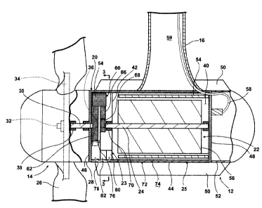
source for the
generator. Initially in flight they are stowed in a compartment of the
aircraft fuselage,
covered by a compartment door. When needed as a source of emergency or
supplemental
power, the RAT system is deployed from the fuselage into the surrounding
airstream, which
drives the blades to rotate the generator to extract energy from the
airstream.
[2] As power requirements for aircraft systems increase, the power generation
capabilities of RAT systems continue to increase. Higher power generators tend
to be
configured to rotate at speeds greater than the rotational speed of the
turbine by utilizing a
gearbox between the turbine and the generator. The higher power generators,
including the
gearbox, tend to generate sufficient heat to make it impossible to cool solely
by the airstream
and use liquid cooling systems, including a heat exchanger, which projects
into the airstream.
BRIEF DESCRIPTION OF THE INVENTION
[3] In one embodiment, a ram air turbine system, for generating electrical
power in an
aircraft when the system is exposed to an airstream exterior of the aircraft,
includes a turbine
having multiple blades and a turbine output shaft operably coupled to the
blades such that
rotation of the blades rotates the turbine output shaft, a housing defining an
interior, a
gearbox located in the interior and having a speed-increasing gear train with
a gearbox output
element and operably coupled to the turbine output shaft such that the gearbox
output
element rotates at a faster speed than the blades, a generator located within
the interior and
having a stator and a rotor where the rotor is operably coupled to the gearbox
output element,
and an integrated heat exchanger for cooling the gearbox and the generator.
1
CA 02790062 2012-09-13
251671-3
BRIEF DESCRIPTION OF THE DRAWINGS
[4] In the drawings:
[5] FIG. I is a side view illustrating a portion of an aircraft having a ram
air turbine with
integrated heat exchanger in accordance with one embodiment of the invention;
[6] FIG. 2 is a schematic cross sectional view of the ram air turbine and
integrated heat
exchanger of FIG. 1;
[7] FIG. 3 is a schematic cross sectional view of the ram air turbine and
integrated heat
exchanger of FIG. 1;
[8] FIG. 4 is a schematic cross sectional view of a portion of a ram air
turbine with an
integrated heat exchanger according to a second embodiment of the invention;
and
[9] FIG. 5 is a schematic cross sectional view of a portion of a ram air
turbine with an
integrated heat exchanger according to a third embodiment of the invention.
DESCRIPTION OF EMBODIMENTS OF THE INVENTION
[10] As illustrated in FIG. 1, an aircraft 10 may include a RAT system 12 for
generating
electrical power for the aircraft 10 when the RAT system 12 is exposed to the
airstream
exterior of the aircraft 10. The RAT system 12 may include a RAT 14, which may
be
suspended from the aircraft 10 by a strut 16 and mounting assembly 18. The RAT
14 may be
stored within a suitable compartment in the fuselage or wing of the aircraft
10 and may be
deployed quickly and easily by moving the strut 16 relative to the mounting
assembly 18,
thereby moving the RAT system 12 to an exposed position within the air stream
flowing past
the aircraft 10. As illustrated in FIG. 2, the RAT 14 includes a housing 20 in
which are
located an electrical generator 22, a gearbox 23 having a gearbox output
element 24, and an
integrated heat exchanger 25. A turbine in the form of multiple blades 26
projecting from a
rotary hub 28 is provided on one end of the housing 20. Although only two
blades 26 have
been shown in the illustrated embodiment it is contemplated that any number of
blades 26
2
CA 02790062 2012-09-13
251671-3
may be used. The turbine further includes a turbine output shaft 30 may be
operably coupled
at a first end 32 to the blades 26 such that rotation of the blades 26 rotates
the turbine output
shaft 30. The turbine output shaft 30 may be operably coupled to the blades 26
in any
suitable manner and may project rearwardly from the blades 26 to provide a
rotary output for
driving an auxiliary power unit, such as the electrical generator 22. By way
of non-limiting
example, a rotor shaft 34 may extend from the blades 26 and may be splined, or
otherwise
suitably mechanically coupled, with the turbine output shaft 30 such that
rotation of the
blades 26 is transferred through the rotor shaft 34 to the turbine output
shaft 30.
Alternatively, the blades 26 or a portion of the rotary hub 28 may be coupled
directly to the
turbine output shaft 30. A second end 36 of the turbine output shaft 30 may be
operably
coupled to a portion of the gearbox 23. The turbine output shaft 30 may be
rotatably
supported within bearings 38 mounted in the rotary hub 28.
[11] The housing 20, as illustrated, comprises a body 44, which is closed by
opposing first
and second end caps 46, 48, to provide a common housing defining an interior
40 for
receiving both the gearbox 23 and generator 22. A wall 42 is provided to
separate the
gearbox portion of the interior 40 from the generator portion of the interior
40 to physically
and fluidly separate the two portions of the interior 40. The housing 20 may
also include a
plurality of heat-dissipating fins or cooling fins 50. The cooling fins 50 may
be formed in
any suitable manner such that they project outwardly from a periphery 52 the
housing 20.
The cooling fins 50 may be spaced about the periphery 52 of the body 44. The
size and
number of the cooling fins 50 may be a function of the specific heat
dissipation requirements
of the RAT system 12.
[12] The generator 22 comprises a stator 54 and a rotor 56 located within the
generator
portion of the interior 40. The rotor 56 may be operably coupled to the
gearbox output
element 24 such that the gearbox output element 24 may provide driving force
for the rotor
56 such that electrical power may be generated. The generator 22 may be
suitably coupled
via conductor cables 58 to the aircraft 10. As illustrated, the RAT system 12
may be carried
at the lower end of strut 16, which may be hollow. The hollow strut 16 may
define a passage
59 through which the conductor cables 58 from the generator 22 may pass to the
aircraft 10.
3
CA 02790062 2012-09-13
251671-3
In this manner, the conductor cables 58, and any other linkages between the
RAT system 12
and the aircraft 10, may be protectively concealed within the strut 16 to
lessen damage.
[13] The gearbox 23 may include a speed-increasing gear train 60. More
specifically, an
input gear 62, a first idler gear 64, a second idler gear 66, and an output
drive gear 68 may be
included in the speed-increasing gear train 60. The input gear 62 may be
referred to by other
names but has been referenced here as an input gear because power is input to
the speed-
increasing gear train 60 of the gearbox 23 at the input gear end of the speed-
increasing gear
train 60. The input gear 62 may be splined or otherwise suitably mechanically
coupled to the
turbine output shaft 30, generally near its second end 36. Input gear 62
meshes with the first
idler gear 64, which has a height spanning across both the input gear 62 and
the second idler
gear 66. In this manner, the first idler gear 64 may mesh with the second
idler gear 66. The
second idler gear 66 may in turn mesh with the output drive gear 68, which may
be splined,
or otherwise suitably mechanically coupled, to the gearbox output element 24,
which is
illustrated as a shaft that may be rotatably supported by bearings 70. The
bearings 70 may be
provided in an arrangement to rotatably support the gearbox output element 24
coaxially with
the turbine output shaft 30.
[14] Other configurations for the gearbox 23, including the gear train 60 are
possible. For
example, although the gearbox 23 is illustrated as being located within the
housing 20 with
the generator 22 it may be in a separate housing coupled to the generator 22.
[15] A coolant circuit 72 is included in the integrated heat exchanger 25 for
cooling the
gearbox 23 and the generator 22. The coolant circuit 72 is illustrated as
extending from the
gearbox 23 to the generator 22 and is formed at least in part by passageways
74 within the
housing 20 such that heat from the gearbox 23 and the generator 22 is
transferred to the
housing 20 by a coolant 76 circulating in the coolant circuit 72. More
specifically, the
passageways 74 may be formed within the body 44 such that they extend a length
of the body
44. The passageways 74 may be formed within the first and second end caps 46
and 48 such
that they fluidly couple the passageways 74 within the body 44 to each other.
4
CA 02790062 2012-09-13
251671-3
[16] A coolant sump 78 may be fluidly coupled to the coolant circuit 72 to
supply coolant
76 to the coolant circuit 72. Any suitable coolant 76 may be used including,
by way of non-
limiting example, oil. A pump 80 may be fluidly coupled to at least one of the
coolant sump
78 and the coolant circuit 72 to recirculate the coolant 76 from the coolant
sump 78 through
the coolant circuit 72. The pump 80 may be any suitable type of pump and by
way of non-
limiting examples may include a simple gear pump, or a gerotor type pump. It
is
contemplated that regardless of the type of pump used the pump 80 may be
driven off of the
speed-increasing gear train 60. A filter assembly 82 may also be located
within the gear box
23 along the coolant circuit 72, preferably adjacent the pump 80 to filter the
coolant 76 to
prevent plugging of the coolant circuit 72. The coolant sump 78 and pump 80
are illustrated
as being located within the gearbox 23. In this configuration, as better
illustrated in FIG. 3,
the input gear 62 may contact the coolant 76 within the coolant sump 78 such
that the coolant
76 may be used as lubrication for the speed-increasing gear train 60.
[17] During operation of the RAT system 12, the RAT 14 is extended into the
airstream
surrounding the aircraft, the airstream flowing over the blades 26 causes the
blades 26 to
rotate, which in turn causes the turbine output shaft 30 to rotate at the same
rotations per
minutes as the blades 26. The turbine output shaft 30 drives the input gear 62
of the speed-
increasing gear train 60, which in turn drives the first and second idler
gears 64 and 66,
which in turn drives the output drive gear 68 and the gearbox output element
24. The speed-
increasing gear train 60 causes the gearbox output element 24 to rotate at a
faster speed than
the blades 26 and acts to convert the low speed incoming rotation to high
speed rotation
suitable for generating electricity.
[18] By way of non-limiting example the generator 22 may be configured to
generate at
least 30kW at 20,000 rpm. More specifically, the ratio of the input gear 62 to
the output
drive gear 68 may be selected such that the output drive gear 68 rotates at a
substantially
greater speed than the input gear 62. The gear configuration and gear ratios
in the speed-
increasing gear train 60 may be selected such that the gearbox output element
24 rotates at
20,000 rpm in response to a predetermined rotational speed of the turbine
output shaft of
6,000 rpm. The rotor 56 is driven by the gearbox output element 24 and causes
the generator
CA 02790062 2012-09-13
251671-3
22 to produce electricity that may be transferred to the aircraft 10 through
the conductor
cables 58.
[19] Along with producing electricity, the RAT system 12 also produces heat.
During
operation the pump 80 may also be driven by the speed-increasing gear train 60
and may
operate to circulate the coolant 76 within the cooling circuit 72. The coolant
76 may be
pumped by the pump 80 through the coolant circuit 72 including the multiple
passageways
74 within the body 44 and first and second end caps 46 and 48 before the
coolant flows into
the coolant sump 78 and through the filter assembly 82 before being pumped by
the pump 80
through the coolant circuit 72 again. When the coolant flows through the
coolant circuit 72 it
may absorb heat from the gearbox 23 and interior 40 of the generator 22, which
is hotter than
the coolant. As the coolant 76 is pumped through the cooling circuit 72 it
carries the
displaced heat. The displaced heat in the coolant 76 may then be dissipated
through the
housing 20 and its cooling fins 50. The cooled coolant repeats this cycle, to
continuously
remove heat from the gearbox 23 and generator 22. The RAT 14, gearbox 23, and
generator
22 are linearly arranged such that the airstream passing through the blades 26
flows over the
gearbox 23 and the housing 20 including the cooling fins 50 to provide for
heat transfer from
the circulating coolant 76 to the airstream. The cooling fins 50 add to the
surface area of the
generator 22 and aid in transferring heat to the surrounding air stream
allowing for greater
heat dissipation from the RAT system 12.
[20] Many other possible embodiments and configurations in addition to that
shown in the
above figures are contemplated by the present disclosure. For example, the
speed-increasing
gear train 60 may also provide the driving power for a hydraulic pump (not
shown). Such a
hydraulic pump may be located such that it may rotate at the same increased
speed as the
generator 22 or may be located such that it may rotate at the slower turbine
speed while the
electrical generator is allowed to rotate at the increased speed. Further, the
design and
placement of the various components may be rearranged such that a number of
different in-
line configurations could be realized.
6
CA 02790062 2012-09-13
251671-3
[211 Furthermore, FIG. 4 illustrates an alternative RAT system 112 with an
integrated heat
exchanger 125 according to a second embodiment of the invention. The second
embodiment
is similar to the first embodiment; therefore, like parts will be identified
with like numerals
increased by 100, with it being understood that the description of the like
parts of the first
embodiment applies to the second embodiment, unless otherwise noted. The
difference
between the first embodiment and the second embodiment is that the cooling
fins 150 of the
heat exchanger 125 also have passageways 190, which may be fluidly coupled to
the
passageways 174 and the remainder of the cooling circuit 172. Although each
cooling fin
150 has been illustrated as having a passageway 190 this need not be the case.
It is possible
for some, but not all, of the cooling fins 150 to have a passageway 190.
Further, with some
of the passageways 190 being located in the cooling fins 150 the number of
passageways in
the housing 120 may be reduced. The coolant in both the passageways 174 and
the
passageways 190 may further aid in displacing heat from the gearbox 23 and
generator 122 to
the surrounding airstream.
[22] FIG. 5 illustrates a third embodiment wherein the RAT system 212 only
includes the
passageways 290 located within the fins 250. The third embodiment is similar
to the first
embodiment; therefore, like parts will be identified with like numerals
increased by 200, with
it being understood that the description of the like parts of the first
embodiment applies to the
third embodiment, unless otherwise noted. In the case of the third embodiment
the
passageways 290 take the place of the passageways within the body 244. Thus,
the first and
second end caps (not shown) would include corresponding fluid passageways to
allow
coolant pumped through the passageways 290 to be in fluid communication with
the
remainder of the cooling circuit 272 including the coolant sump and pump (not
shown).
[23] The embodiments disclosed herein provide a RAT system with an integrated
heat
exchanger. One advantage that may be realized in the above embodiments is that
the above
described embodiments can effectively remove heat from the high power RAT
system. The
cooling fins along the housing increase the cooling surface area and the
coolant circuit
provides an effective means for dissipating heat from the gearbox and
generator. Another
advantage is that the above described embodiments are configured as closed
loop systems
7
CA 02790062 2012-09-13
251671-3
where oil in the coolant sump is recirculated to remove heat from the
generator while also
providing lubrication to the gears in gearbox.
[24] When designing aircraft components, important factors to address are
size, weight,
and reliability. The above described RAT systems have a decreased number of
parts as there
is not a separate heat exchanger or separate plumbing connections. This
results in a lower
weight, smaller sized, and increased reliability system. The lower number of
parts and
reduced maintenance will lead to a lower product costs and lower operating
costs. Reduced
weight and size correlate to competitive advantages during flight.
[25] This written description uses examples to disclose the invention,
including the best
mode, and also to enable any person skilled in the art to practice the
invention, including
making and using any devices or systems and performing any incorporated
methods. The
patentable scope of the invention is defined by the claims, and may include
other examples
that occur to those skilled in the art. Such other examples are intended to be
within the scope
of the claims if they have structural elements that do not differ from the
literal language of
the claims, or if they include equivalent structural elements with
insubstantial differences
from the literal languages of the claims.
8