Note: Descriptions are shown in the official language in which they were submitted.
CA 02790071 2012-09-13
Transportation Device with Star Wheels
The present invention relates to a transportation device for transporting
sausage-
shaped products, like sausages, with suspension elements, like loops, from a
clip-
ping machine to a handling device according to claim 1.
In particular, the present invention relates to a transportation device for
transporting
sausage-shaped products, like sausages, with suspension elements, like loops,
from
a clipping machine to a handling device for said sausage-shaped products like
a
storage device including a bar-shaped storing element, like a smoking rod. The
transportation device comprises a conveying unit for conveying a sausage-
shaped
product just produced out of the clipping machine in a transportation
direction and a
catching unit for catching the suspension element attached to one end of the
sau-
sage-shaped product. The transportation device further comprises a guide unit
for
guiding the suspension element caught by the catching unit to said handling
device.
The guide device comprises a longitudinally extending guide element and
supporting
means for supporting the guide element, wherein the supporting means provide a
passage way for the loop to be guided along the guide element.
In the practice, it is known that, for example in the production of sausage-
shaped
products, like sausages, a filling material is fed by a filling machine
through a filling
tube of a clipping machine into a tubular casing material, which is stored on
the filling
tube and which is closed at its front end, referred to the feeding direction,
by a clos-
ing clip. The tubular casing material is pulled-off from the filling tube
while being
filled. After a predetermined volume of filling material is filled into said
tubular casing
material, a displacement device with a first and a second pair of displacement
ele-
ments forms a plait-like portion of the tubular casing material and the
clipping ma-
chine places and closes at least one closing clip at the plait-like portion
forming the
back end of the sausage shaped product by respective closing tools which are
re-
versibly movable towards the plait-like portion. After that the sausage-shaped
prod-
CA 02790071 2012-09-13
-2-
uct just produced, is separated from the remaining casing material by a knife
or the
like of a cutting device of the clipping machine and is transferred to a
storage device
or another machine for the next producing step.
From DE patent 38 06 467, an apparatus for producing sausages, and
transferring
said sausages to a storage device, in particular to a smoking rod, is known.
The
device for discharging the sausage just produced out of the clipping machine
and
transferring said sausage to the smoking rod of said known apparatus includes
a
sword having a first or tip end directed towards the clipping machine, for
catching the
suspension loop attached to said sausage, as well as a second end opposite to
the
tip end. Moreover, there is provided a chain conveyor for transferring the
sausages
hanging on the sword to a smoking rod. A belt conveyor carries the sausage
just
produced out of the clipping machine, whereby the suspension loop is shifted
along
the sword. For holding the sword in position, and for enabling the suspension
loop
passing the sword, said sword is held by pistons laterally engaging the sword.
For
allowing the suspension loop to pass the pistons, said pistons can alternately
be
disengaged from the sword.
For a trouble-free operation, a complex control of said apparatus is
necessary, like
coordinating the movement of the pistons with the transportation speed of the
belt
conveyor and the production rate of the clipping machine. Moreover, said
pistons
may not be moved at a high speed, thereby limiting the maximum production rate
of
the clipping machine.
Thus, it is an object of the present invention to provide a transportation
device for
transporting sausage-shaped products from a clipping machine to a handling
device
with which the above mentioned drawbacks are overcome and which enables a save
transfer or transportation, respectively, of said sausage-shaped products from
said
clipping machine to said handling device.
The aforesaid object is achieved by the features of claim 1. Advantageous
configura-
tions of the clipping machine are described in claims 2 to 9.
CA 02790071 2012-09-13
-3-
According to the present invention, there is provided a transportation device
for
transporting sausage-shaped products, like sausages, with suspension elements,
like loops, from a clipping machine to a handling device for said sausage-
shaped
products, like a storage device including a bar-shaped storing element, like a
smok-
ing rod. The transportation device comprises a conveying unit for conveying a
sau-
sage-shaped product just produced out of the clipping machine in a
transportation
direction and a catching unit for catching the suspension element attached to
one
end of the sausage-shaped product. The transportation device further comprises
a
guide unit for guiding the suspension element caught by the catching unit to
said
handling device. The guide unit comprises a longitudinally extending guide
element
and supporting means for supporting the guide element, wherein the supporting
means provide a passage way for the loop to be guided along the guide element.
In an advantageous embodiment of the inventive transportation device, the
support-
ing means include gear or star wheels arranged rotatably about an at least
substan-
tially horizontally aligned axis, engaging the guide element; and there are
provided
ratchets for engaging the gear wheels, adapted to position a gap between two
sub-
sequent teeth of said gear wheels in the passage way of said suspension
element.
In this configuration, the guide element is securely held in position by the
gear
wheels. Moreover, when positioning the gear wheels with a gap between two
subse-
quent teeth of said gear wheels in the passage way of said suspension element,
a
save guidance of the suspension element along the guide element is ensured, in
particular, any blocking of the suspension element is avoided.
According to a further advantageous embodiment, recesses are provided in the
guide element, into which the gear wheels engage or interfere, respectively.
There-
by, the guide element is securely held in position by said gear wheels without
block-
ing the passage way of the suspension elements.
At the end of the guide element facing the clipping machine, the catching
unit, like a
catching pin or needle, is mounted and held in position by said guide element.
In
CA 02790071 2012-09-13
-4-
order to prevent the guide element, and thus, also the catching
transportation, from
being displaced or from being brought out of alignment with the clipping
machine, at
least four gear wheels are provided, two gear wheels are positioned below the
guide
element and two gear wheels are positioned above the guide element. In this
config-
uration, space is left on both sides of the guide element, for accurately
place the
conveying unit, like a conveyor belt, e.g. dependent on the length and/or the
diame-
ter of the sausage-shaped product, for carrying said sausage-shaped product
out of
the clipping machine.
According to a further embodiment of the inventive discharge device, at least
four
ratchets are provided, each of which engage one of the at least four gear
wheels. In
this embodiment, each of the gear wheels is provided with a ratchet for
securely
positioning the gap between two subsequent teeth of said gear wheels in the
pas-
sage way of said suspension element.
For further preventing the guide element from being displaced or from being
brought
out of alignment with the transportation means of the clipping machine, the
recesses
in the guide element correspond to the shape of the gear wheels. For example,
by
selecting a width of the recesses, at least approximately corresponding to the
width
of the gear wheels, rotation of the guide unit about its longitudinal axis is
prevented
or at least minimized.
For a further stabilization of the guide unit, the gear wheels positioned
below the
guide element and the gear wheels positioned above the guide element are
aligned
with a horizontal offset to eachother. In this configuration, only one of the
gear
wheels is rotated at a time, while a suspension element is guided along the
guide
element, whereby the frictional forces acting on the guide element, are
reduced.
Moreover, the cross sectional dimension, e.g. the diameter, of the guide
element
may be reduced.
CA 02790071 2012-09-13
-5-
In a preferred embodiment of the inventive transportation device, the ratchets
are
spring-loaded, for enabling independent operation of the ratchets without any
addi-
tional drive means.
In a preferred embodiment of the inventive transportation device, the ratchets
have
an effective surface acting on the gear wheels. In particular, the effective
surface
includes an inclined portion and a recess portion. The inclined portion
enables the
rotational movement of the gear wheels, whereas the recess portion securely
and
accurately holds the gear wheels in a position, where the gap between two
subse-
quent teeth of said gear wheels is in the passage way of said suspension
element.
In the following, further advantages and embodiments of the inventive method
and
the inventive clipping machine are described in conjunction with the attached
draw-
ings. Thereby, the expression "left", "right", "below" and "above" are
referred to the
drawings in an orientation of the drawings which allows the normal reading of
the
reference numbers.
In the drawings:
Fig. 1: is a perspective and schematically view of a transportation device for
transporting sausage-shaped products according to the present inven-
tion; and
Fig. 2: is a sectional view of the transportation device according to the
present
invention in a vertical plane through the guide element.
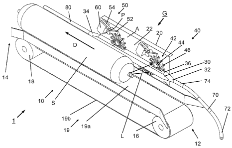
Fig. 1 is a schematically view of a transportation device 1 for transporting
sausage-
shaped products S, like sausages, with suspension elements L, like loops, from
a
clipping machine to a handling device for said sausage-shaped products S
according
to the present invention. Transportation device 10 has a first or entry end 12
which is
directed towards the clipping machine (not shown) and a second or exit end 14
extending away from said clipping machine in a transportation direction D.
CA 02790071 2012-09-13
-6-
Transportation device 1 according to Fig. 1 includes a conveying unit 10 in
the form
of a belt conveyor. Belt conveyor 10 includes a first roller 16 and a second
roller 18,
both arranged at least substantially horizontally and in succession in
discharge direc-
tion D, and a conveyor belt 19 wound around first and second rollers 16, 18.
Con-
veyor belt 19 has an upper run 19a and a lower run 19b. Belt conveyor 10 has a
drive (also not shown) for driving belt 19 in order to transport sausage S out
of the
clipping machine in discharge direction D.
A guide unit G is positioned laterally to and above belt conveyor 10, with a
vertically
arranged frame element 20 which is aligned parallel to the longitudinal
extension of
belt conveyor 10 and in discharge direction D. At a side surface 22 of frame
element
20, which faces to belt conveyor 10, a bar-shaped guide element 30 is arranged
above and at least substantially parallel to belt conveyor 10 and, extends in
dis-
charge direction D, with a first end 32 directed towards the clipping machine
and a
second end 34 facing away from said clipping machine.
Supporting means 40 including four star or gear wheels 42 for supporting guide
element 30 are arranged at surface 22 of frame element 20 fueing to belt
conveyor
10. Four ratchets 50 are attached to side surface 22 of frame element 20, each
ratchet 50, which will be explained in detail in conjunction with Fig. 2,
comprises a
first lever or engagement lever 52 pivotable about a pivot axis P, and is
positioned
laterally to one of the gear wheels 42 for engaging said gear wheel 42 with
engage-
ment lever 52.
As it can be seen in Fig. 1, each gear wheel 42 has a centre hub 44 and a
number of
teeth 46 extending radially from centre hub 44. All teeth 46 have the same
length
and are arranged in regular intervals around centre hub 44. Teeth 46 engage
guide
element 30 by recesses 36 provided in the upper and lower surface of guide
element
30.
Transportation device 1 further comprises a catching unit 70 in the form of a
catching
needle. Needle 70 has a first end 72 and a second end 74. Needle 70 is mounted
by
CA 02790071 2012-09-13
-7-
its second end 64 to first end 32 of guide element 30 and extends with its
first end 72
towards the clipping machine. As it can be seen in Fig. 1, needle 70 has a
generally
circular cross-section and is bent downwardly to reach into the closing area
of the
clipping machine and to catch a loop attached to the sausage S just produced
in said
clipping machine.
At second end 34 of guide element 32, a guide rail 80 for guiding loop L of
sausage
S to a storing element, like a smoking rod, is arranged, extending
horizontally in
discharge direction D.
Fig. 2 is a sectional view of the transportation device 1 according to the
present
invention shown in Fig. 1, in a vertical plane through the guide element 30.
As it can be seen in Fig. 2, four gear wheels 42 engage horizontally aligned
guide
element 30. Two gear wheels 42 are arranged above guide element 30 and two
gear
wheels 42 are positioned below guide element 30. Each upper gear wheel 42 is
positioned above the respective lower gear wheel 42, and with a horizontal
offset
thereto in the direction toward the not shown clipping machine. That means,
recess-
es 36 in guide element 30 are not positioned vertically above each other and
thus,
they do not overlap each other. Accordingly, dependent on the necessary depth
of
recesses 36, the vertical height, or its diameter respectively, of guide
element 30
may be chosen as small as possible.
Recesses 36 according to Fig. 2 have an approximately semicircular shape for
ena-
bling gear wheels 42 to engage said recesses 36. The diameter of recesses 36
corresponds at least to the diameter of gear wheels 42. The vertical depth of
recess-
es 36 is slightly smaller than the length of teeth 44 to provide a passage way
for
suspension loop L between the upper surface of guide element 30 and the lower
most point of centre hub 42, as well as the lower surface of guide element 30
and
the upper most point of centre hub 42 respectively.
CA 02790071 2012-09-13
-8-
As it can be seen in Fig. 1, the horizontal width of recesses 36 in the
direction normal
to discharge direction D corresponds at least to the respective width of gear
wheels
42, or at least to the respective width of teeth 46 of gear wheels 42. Centre
hub 44 of
gear wheels 42 may be larger in width than teeth 46, since only teeth 46
engage
recesses 36 of guide element 30.
As mentioned above four ratchets 50 are provided, each of which engages one of
the four gear wheels 42. Each ratchet 50 comprises first lever or engagement
lever
52, and a second lever 54 coupled to engagement lever 52. Levers 52, 54 are
com-
monly pivotable about pivot axis P. The free end of second lever 54 is coupled
to an
actuation device 60. Actuation device 60 includes a housing 62 attached to
side
surface 22 of frame element 20, and an actuation element in the form of a
spring 64,
which, according to Fig. 2, is a compression spring, accommodated in housing
62.
Spring 64, or its actuation direction respectively, is aligned vertically to
second lever
54, for acting on second lever 54, whereby the free end of engagement lever 52
is
urged against the outer ends of teeth 46 of the respective gear wheel 42.
As it further can be seen in Fig. 2, the effective surface of engagement lever
52
which faces the respective star wheel 42, has an inclined portion 52a and a
recess
portion 52b. Inclined portion 52a extends from the free end of engagement
lever 52
towards pivot axis P, and terminates in recess portion 52b which is positioned
ap-
proximately in the middle of engagement lever 52. In the region of the
inclined por-
tion 52a, the vertical height of engagement lever 52 reduces from its free
end, where
the height is maximal, towards recess portion 52b. The remaining portion of en-
gagement lever 52 has an approximately constant vertical height. The dimension
of
recess portion 52a in the longitudinal direction of lever 52 corresponds to
the respec-
tive circumferential dimension of the teeth 46 of gear wheels 42.
The maximum length of inclined portion 52a is approximately equal to the gap
be-
tween two subsequent teeth 46 of gear wheel 42, in particular to the maximum
dis-
tance between the free ends of two subsequent teeth 46 of gear wheel 42, to
enable
inclined portion 52a to engage the gap between the respective next two
subsequent
CA 02790071 2012-09-13
-9-
teeth 46 of gear wheel 42, when gear wheel 42 is rotated about axis A by a
suspen-
sion loop pulled over guide element 30.
While producing a sausage-shaped product or sausage S, filling material is fed
into a
tubular packaging material, which is closed by a closure means, like a closure
clip,
when a predetermined portion of filling material has bee fed. Normally,
together with
said clip, a suspension loop S is fixed to the respective end of the sausage
S. While
feeding said loop L to the closing tools and the closure clip respectively,
said loop L
is caught by catching unit or catching needle 70 which engages suspension loop
L.
During the filling process, sausage S is positioned at upper run 19a of belt
19 of belt
conveyor 10, with the end including suspension loop L directed towards the
clipping
machine.
For discharging sausage S just produced from the clipping machine, belt
conveyor
10 is driven by a respective drive (not shown), whereby sausage S is
transported in
discharge direction D. Thereby, loop L caught by catching needle 70 is shifted
along
needle 70, guide element 30 and guide rail 80. Subsequent to guide rail 80, a
storing
element, like a smoking rod may be provided for storing sausage S thereon.
While passing guide element 30, loop L engages the gap between two subsequent
teeth 46 of the first upper star wheel 42 from the right side according to
Figs. 1 and
2, and indicated as position L1 in Fig. 2, at the upper side of guide element
30. Dur-
ing the further movement of sausage S in discharge direction D, loop L is
pulled over
guide element 30. Thereby, gear wheel 42 is rotated clockwise about axis A.
While leaving the gap between subsequent teeth 46 of gear wheel 42 at the left
side
of said first gear wheel 42, loop L engages the gap between subsequent teeth
46 of
the second, lower gear wheel 42 at the lower side of guide element 30.
During the rotational movement of first upper gear wheel 42, engagement lever
52,
and second lever 54 respectively, has been pivoted counterclockwise, actuated
by
CA 02790071 2012-09-13
-10-
the free end of tooth 46 of first upper gear wheel 42, which initially has
been posi-
tioned in recess portion 52b, and which has been moved along inclined portion
52a.
After said free end of tooth 46 of first upper gear wheel 42 has left
engagement lever
52, engagement lever 52 has been pivoted clockwise about pivot axis P,
actuated by
spring 64 acting on the free end of second lever 54. Inclined portion 52a of
engage-
ment lever 52 thereby acts on the free end of the subsequent tooth 46. Said
subse-
quent tooth 46 is guided along inclined portion 52a, at least by its left end
portion,
towards recess portion 52b, and the free end of said tooth 46 engages recess
por-
tion 52b. Accordingly, a next recess between two subsequent teeth 46 of gear
wheel
42 at the right side of said first gear wheel 42 has been positioned at the
upper sur-
face of guide element 30 in order to accommodate suspension loop L of the next
sausage S to be produced, as shown in Figs. 1 and 2.
It has to be understood, that ratchets 50 at all gear wheels 42 are positioned
and
aligned as described above, in order to provide a gap at the respective upper
and/or
lower surface of guide element 30 enabling accommodating suspension loop L of
the
sausage S to be guided along guide element 30.
Transportation device 1 has been described as comprising 4 gear wheels 42, two
upper gear wheels 42 and two lower gear wheels 42. Naturally, according to the
length of guide element 30, more than four gear wheels 42 may be provided for
supporting guide element 30. In a simple case, guide device 30 may also be
held
only by three gear wheels 42.
Teeth 46 of transportation device 1 according to Figs. 1 and 2 have an
approximately
cuboid shape with parallel side surfaces. Teeth 46 may also have any other
suitable
shape, like a pyramidal shape including a plat end or a tip end. In this case,
the
shape of the recesses should also correspond the shape of the teeth.
The ratchets for engaging the gear wheels 42 may also have any other suitable
construction than that shown in Figs. 1 and 2. For example, the actuation unit
60
CA 02790071 2012-09-13
-11-
may directly act on the engagement lever 52, whereby a second lever is not
neces-
sary. It has some importance, that the ratchet 50 is constructed to enable a
loop to
be guided along the guide element 30, and that the gear wheel 42 is brought in
a
position by the ratchet 50, in which a gap between two subsequent teeth is
provided
at the respective surface of the guide element 30 to allow a loop to engage
said gap
without being blocked.
Other suitable actuation devices may be provided, like tension springs or
elastic
elements made of rubber or the like, for acting on the engagement lever 52.
Moreover, the cross-section of the catching needle 78 may depart from the
circular
to cross-section shown in Fig. 1. Also, the guide element 30 may have any
suitable
cross section like a circular or a rectangular cross-section.
The conveying unit 10 may not necessarily be a belt conveyor. Any suitable
convey-
or means may be used to transport the sausage-shaped products along the
catching
needle 72 and the guide element 30. In the simplest case, a chute may be
provided
on which the sausage-shaped products slides along the guide element.
Alternatively,
other driven conveying means may be used, like chain conveyors including
engage-
ment elements like hooks, for engaging and pulling the sausage-shaped product
along the guide element.
It has to be understood, that a housing may be provided for accommodating the
guide device, for preventing an unintentional or accidental engagement of the
mov-
ing parts of the guide device, like the gear wheels.
Finally, the ratchets 50 may also be formed by other means as long as these
other
means are able to keep reversibly each gear wheel in a stand by position such
that
the teeth of the gear wheel allows the entrance of a suspension loop into the
inter-
mediate portion between two successive teeth of a gear wheel.