Language selection

Search

Patent 2790085 Summary

Third-party information liability

Some of the information on this Web page has been provided by external sources. The Government of Canada is not responsible for the accuracy, reliability or currency of the information supplied by external sources. Users wishing to rely upon this information should consult directly with the source of the information. Content provided by external sources is not subject to official languages, privacy and accessibility requirements.

Claims and Abstract availability

Any discrepancies in the text and image of the Claims and Abstract are due to differing posting times. Text of the Claims and Abstract are posted:

  • At the time the application is open to public inspection;
  • At the time of issue of the patent (grant).
(12) Patent: (11) CA 2790085
(54) English Title: ELASTOMERIC BEARING WITH TAPERED SHIMS
(54) French Title: COUSSINET ELASTOMERE AVEC CALES EFFILEES
Status: Granted
Bibliographic Data
(51) International Patent Classification (IPC):
  • F16C 27/06 (2006.01)
  • B64C 27/32 (2006.01)
  • B64C 27/35 (2006.01)
  • B64C 27/37 (2006.01)
  • B64C 27/48 (2006.01)
  • B64C 27/51 (2006.01)
  • F16C 7/04 (2006.01)
  • F16C 17/04 (2006.01)
  • F16C 27/08 (2006.01)
(72) Inventors :
  • SOTTIAUX, DANIEL P. (United States of America)
  • STAMPS, FRANK B. (United States of America)
(73) Owners :
  • BELL HELICOPTER TEXTRON INC. (United States of America)
(71) Applicants :
  • BELL HELICOPTER TEXTRON INC. (United States of America)
(74) Agent: NORTON ROSE FULBRIGHT CANADA LLP/S.E.N.C.R.L., S.R.L.
(74) Associate agent:
(45) Issued: 2015-11-03
(22) Filed Date: 2012-09-13
(41) Open to Public Inspection: 2013-04-03
Examination requested: 2012-09-13
Availability of licence: N/A
(25) Language of filing: English

Patent Cooperation Treaty (PCT): No

(30) Application Priority Data:
Application No. Country/Territory Date
61/542,584 United States of America 2011-10-03
13/597,433 United States of America 2012-08-29

Abstracts

English Abstract

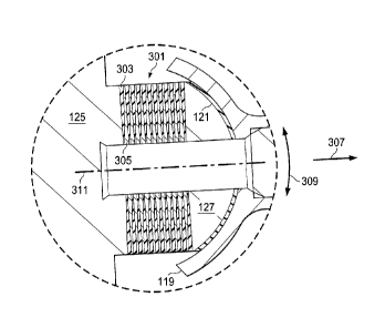
The centrifugal force bearing includes a plurality of tapered metal shims such that the thicker end of each tapered metal shim near the inner portion of bearing. The bearing can include a plurality of tapered elastomeric members that are consequently tapered so that the inner portions are narrower than the outer portions. The tapered metal shims can increase the axial stiffness in the direction of the centrifugal force, thereby reducing the axial deflection under loading, as compared to non-tapered shims. Further, reducing axial deflection reduces clearance issues that may arise when the rotor blade is allowed to axial deflect significant distances. As such, the tapered metal shims can increase the capacity of the bearing. Tapering the metal shims can decrease the compression induced shear strain near the outer portions of the elastomeric member, where loads are typically higher.


French Abstract

Le coussinet de force centrifuge comprend une pluralité de cales métalliques effilées de sorte que lextrémité plus épaisse de chaque cale métallique effilée se trouve proche de la partie intérieure du coussinet. Le coussinet peut comprendre une pluralité déléments élastomères effilés qui sont par conséquent effilés de manière à ce que les parties intérieures soient plus étroites que les parties extérieures. Les cales métalliques effilées peuvent accroître la rigidité axiale dans le sens de la force centrifuge, réduisant ainsi la déflexion axiale sous la charge, comparativement à des cales non effilées. En outre, réduire la déflexion axiale réduit les problèmes de dégagement qui peut survenir quand on permet à lailette de rotor à fléchir axialement sur des distances importantes. Comme telles, les cales métalliques effilées peuvent augmenter la capacité du coussinet. Effiler les cales métalliques peut réduire la déformation de cisaillement induite par la compression à proximité des parties extérieures de lélément élastomère, là où les charges sont habituellement plus élevées.

Claims

Note: Claims are shown in the official language in which they were submitted.


Claims

1. A bearing comprising:
a base member;
a cap member;
alternating layers of shim members and elastomeric members between the
base member and the cap member, the shim members being tapered;
wherein the bearing is a centrifugal force bearing for a rotor hub.
2. The bearing according to claim 1, wherein the shim members are tapered
such that a narrow portion thereof is located near an outer portion of the
bearing.
3. The bearing according to claim 1, wherein the elastomeric members are
tapered such that a wide portion thereof is located near an outer portion of
the
bearing.
4. The bearing according to claim 2, wherein the elastomeric members are
tapered such that a wide portion thereof is located near the outer portion of
the
bearing.
5. The bearing according to any one of claims 1 to 4, wherein the shim
members
are tapered such that a wide portion thereof is located near an inner portion
of the
bearing.
6. The bearing according to any one of claims 1 to 4, wherein the
elastomeric
members are tapered such that a narrow portion thereof is located near an
inner
portion of the bearing.
7. The bearing according to claim 5, wherein the elastomeric members are
tapered such that a narrow portion thereof is located near the inner portion
of the
bearing.
8. The bearing according to any one of claims 1 to 7, wherein the shim
members
include a metal material.

Page 7


9. The bearing according to any one of claims 1 to 8, wherein the shim
members
include a composite material.
10. The bearing according to any one of claims 1 to 9, further comprising:
a bearing support having an inner spherical surface that is joint to an outer
spherical surface of the cap member with an elastomeric portion.
11. The bearing according to any one of claims 1 to 10, wherein the base
member
is adapted for coupling to a rotor grip portion of the rotor hub.
12. The bearing according to any one of claims 1 to 11, wherein the cap
member
is adapted for coupling to a rotor yoke via a bearing support.
13. A centrifugal force bearing for a rotor hub, the centrifugal force
bearing
comprising:
a plurality of shim layers that are tapered;
a plurality of elastomeric layers;
wherein the shim layers are tapered such that a wide portion of the shim
layers are oriented toward an inner portion of the centrifugal force bearing.
14. The centrifugal force bearing according to claim 13, the centrifugal
force
bearing further comprising:
a base member configured for coupling to a rotor grip.
15. The centrifugal force bearing according to claim 13 or 14, the
centrifugal force
bearing further comprising:
a support member configured for coupling to a rotor yoke.
16. The centrifugal force bearing according to claim 15, wherein an
operation of
the rotor yoke acts to compress the plurality of elastomeric layers.

Page 8


17. The centrifugal force bearing according to any one of claims 13 to 16,
wherein
the plurality of elastomeric layers and the plurality of the shim layers are
oriented
substantially perpendicular to a pitch change axis of a rotor blade of the
rotor hub.
18. The centrifugal force bearing according to any one of claims 13 to 17,
wherein
the elastomeric layers are tapered such that a narrow portion of the
elastomeric
layers are located toward an inner portion of the centrifugal force bearing.
19. The centrifugal force bearing according to any one of claims 13 to 18,
further
comprising:
a cap member located outboard of the plurality of elastomeric layers and the
plurality of shim layers.
20. The centrifugal force bearing according to any one of claims 13 to 19,
wherein
the elastomeric layers and the shim layers are in an alternating arrangement.
21. The centrifugal force bearing according to any one of claims 13 to 20,
wherein
a pitch change of a rotor blade acts to torsionally deform the plurality of
elastomeric
layers about a central axis of the centrifugal force bearing, the elastomeric
layers
being thicker near an outer portion.

Page 9

Description

Note: Descriptions are shown in the official language in which they were submitted.


CA 02790085 2014-06-26
ELASTOMERIC BEARING WITH TAPERED SHIMS
BACKGROUND
Technical Field:
The apparatus of the present application relates to a centrifugal force
bearing for a
rotor hub.
Description of Related Art:
Centrifugal force bearings can include a combination of elastomeric members
and
metal shims of uniform thickness. The compression induced shear strain of the
elastomeric members is typically the leading life limiter of the bearing.
Hence, there is a need for an improved bearing design having reduced
compression
induced shear strain during operation. Further, there is a need for a bearing
that
provides increased load capacity without increasing the size of the bearing.
SUMMARY
In one aspect, there is provided a bearing comprising: a base member; a cap
member; alternating layers of shim members and elastomeric members between the

base member and the cap member, the shim members being tapered; wherein the
bearing is a centrifugal force bearing for a rotor hub.
In another aspect, there is provided a centrifugal force bearing for a rotor
hub, the
centrifugal force bearing comprising: a plurality of shim layers that are
tapered; a
plurality of elastomeric layers; wherein the shim layers are tapered such that
a wide
portion of the shim layers are oriented toward an inner portion of the
centrifugal force
bearing.
Page 1

CA 02790085 2012-09-13
DESCRIPTION OF THE DRAWINGS
The novel features believed characteristic of the apparatus of the present
application
are set forth in the appended claims. However, the apparatus itself, as well
as a
preferred mode of use, and further objectives and advantages thereof, will
best be
understood by reference to the following detailed description when read in
conjunction with the accompanying drawings, wherein:
Figure 1 is a side view of a rotorcraft having a bearing, according to an
illustrative
embodiment of the present application;
Figure 2 is a top sectional view of the main rotor hub of the rotorcraft,
taken at
section lines 2-2 in Figure 1, according to an illustrative embodiment of the
present
application;
Figure 3 is a cross-sectional view of the main rotor hub, taken from section
lines 3-3
in Figure 2, according to the illustrative embodiment of the present
application; and
Figure 4 is an enlarged cross-sectional view of the bearing, according to the
illustrative embodiment of the present application.
Page 2

CA 02790085 2012-09-13
DESCRIPTION OF THE PREFERRED EMBODIMENT
Illustrative embodiments of the apparatus are described below. In the interest
of
clarity, all features of an actual implementation may not be described in this

specification. It will of course be appreciated that in the development of any
such
actual embodiment, numerous implementation-specific decisions must be made to
achieve the developer's specific goals, such as compliance with system-related
and
business-related constraints, which will vary from one implementation to
another.
Moreover, it will be appreciated that such a development effort might be
complex
and time-consuming but would nevertheless be a routine undertaking for those
of
ordinary skill in the art having the benefit of this disclosure.
In the specification, reference may be made to the spatial relationships
between
various components and to the spatial orientation of various aspects of
components
as the devices are depicted in the attached drawings. However, as will be
recognized by those skilled in the art after a complete reading of the present

application, the devices, members, apparatuses, etc. described herein may be
positioned in any desired orientation. Thus, the use of terms such as "above,"

"below," "upper," "lower," or other like terms to describe a spatial
relationship
between various components or to describe the spatial orientation of aspects
of such
components should be understood to describe a relative relationship between
the
components or a spatial orientation of aspects of such components,
respectively, as
the device described herein may be oriented in any desired direction.
The apparatus of the present application is a bearing having alternating
layers of
tapered shims and tapered elastomeric members that are collectively configured
to
reduce compression induced shear strain of the elastomeric members. It should
be
appreciated that even though the tapered shims are described herein as being
metal, tapered shims can be manufactured with any rigid material, such as a
composite material for example.
Referring to Figure 1, an example rotorcraft 101 is illustrated. Rotorcraft
101 can
include a fuselage 103, a landing gear 105, a tailboom 107, a main rotor
system 109
having rotor blades 123, and a tail rotor system 111. It should be appreciated
that
rotorcraft 101 is merely illustrative of a wide variety of aircraft that can
implement the
Page 3

CA 02790085 2012-09-13
apparatus discloses herein, such as bearing 301. Other aircraft
implementations can
include hybrid aircraft, tilt rotor aircraft, unmanned aircraft, gyrocopters,
and a variety
of helicopter configurations, to name a few examples.
Referring to Figures 2 and 3, main rotor system 109 can include rotor yokes
117 and
rotor grips 115. Each rotor grip 115 is configured for receiving and coupling
to one of
rotor blades 123. During operation, the rotation of the rotor blades 123
around an
axis of rotation, defined by a rotor mast 113, can cause a centrifugal force
307 that is
reacted by compression of bearing 301. A bearing support 119 can be used to
provide a bearing surface for bearing 301. Further, bearing 301 can have a
base
member 125 configured for coupling to rotor grip 115. Bearing 301 can be
configured to react compressive, torsional, and flapping motions between rotor
blade
123 and rotor yoke 117.
Referring to Figure 4, a cross-sectional view through bearing 301 is
illustrated.
Bearing 301 includes a plurality of tapered metal shims 305 such that the
thicker end
of each metal shim 305 is near the inner portion of bearing 301. As shown in
Figure
4, each metal shim 305 is narrower toward the outer portion of bearing 301.
Bearing
301 can further include a plurality of tapered elastomeric members 303 that
are
consequently tapered so that the inner portions are narrower than the outer
portions.
Bearing 301 can have a cap member 127 located between the alternating layers
of
tapered shims 305 and tapered elastomeric members 303. Cap member 127 can be
a rigid member that mates to the outboard elastomeric member 303 and
elastomeric
portion 121, the elastomeric portion 121 being configured as a joint between
the
mating spherical surfaces of cap member 127 and bearing support 119.
When subjected to a centrifugal force 307, the tapered metal shims 305
function to
increase the axial stiffness in the direction of the centrifugal force 307.
One
beneficial result is that increasing axial stiffness, a reduction in the axial
deflection
under loading is achieved, as compared to non-tapered shims. The increase in
axial
stiffness in direction 307 can be attributed to the majority of the
operational
compression load being reacted by the interior portion (where metal shims 305
are
thicker), thereby preventing the outer portions (wherein the elastomeric
members
303 are thicker) from reacting the compression load, which reduces compression

induced shear strain near the outer portions of the elastomeric members 303,
where
Page 4

CA 02790085 2012-09-13
loads are typically higher. Since compression induced shear strain typically
drives
the size of the bearing during design, bearing 301 can be sized smaller than a

convention bearing having non-tapered shims, while having the same capability.
Further, reducing axial deflection reduces clearance issues that may arise
when the
rotor blade is allowed to axial deflect significant distances. As such,
tapering metal
shims 305 can increase the capacity of the bearing 301, as compared to non-
tapered
shims.
During operation, bearing 301 may be subjected to not only a centrifugal force
307,
but also a flapping (cocking) force 309. An elastomeric portion 121 can be
configured to deflect upon a flapping force 309. Further, elastomeric members
303
can also deflect when subjected to flapping force 309.
Further, during operation a torsional load can be subjection on the bearing
301 when
the pitch of rotor blade 123 is changed. The resulting torsional deflection
can occur
about a centerline axis 311, which also corresponds to the pitch change axis
of the
rotor blade 123. Another unique advantage to bearing 301 is that since the
outer
portion has more elastomeric material, as compared to the inner portion, the
elastomeric members 303 can carry the strain from the torsional loading.
Having a
bearing that carry the torsional strain, while act stiff in axial compression
can be very
desirable. Further, the degree and size of the tapered metal shims 305 and
tapered
elastomeric members 303 can be selected to individually tailor the torsional
capacity
and axial stiffness of bearing 301.
The bearing of the present application provides significant advantages,
including: 1)
decreasing compression induced shear strain of the elastomeric portions of the

bearing, 2) increasing a usage life of the bearing, 3) reducing the size of
the bearing,
4) increasing the torsional capacity of the bearing, and 5) increase axial
compression
stiffness so as to decrease load deflection and clearance requirements.
The particular embodiments disclosed above are illustrative only, as the
apparatus
may be modified and practiced in different but equivalent manners apparent to
those
skilled in the art having the benefit of the teachings herein. Modifications,
additions,
or omissions may be made to the apparatuses described herein without departing

from the scope of the invention. The components of the apparatus may be
Page 5

CA 02790085 2014-06-26
integrated or separated. Moreover, the operations of the apparatus may be
performed by more, fewer, or other components.
Furthermore, no limitations are intended to the details of construction or
design
herein shown, other than as described in the claims below. It is therefore
evident
that the particular embodiments disclosed above may be altered or modified and
all
such variations are considered within the scope of the application.
Accordingly, the
protection sought herein is as set forth in the claims below.
Page 6

Representative Drawing
A single figure which represents the drawing illustrating the invention.
Administrative Status

For a clearer understanding of the status of the application/patent presented on this page, the site Disclaimer , as well as the definitions for Patent , Administrative Status , Maintenance Fee  and Payment History  should be consulted.

Administrative Status

Title Date
Forecasted Issue Date 2015-11-03
(22) Filed 2012-09-13
Examination Requested 2012-09-13
(41) Open to Public Inspection 2013-04-03
(45) Issued 2015-11-03

Abandonment History

There is no abandonment history.

Maintenance Fee

Last Payment of $263.14 was received on 2023-09-08


 Upcoming maintenance fee amounts

Description Date Amount
Next Payment if standard fee 2024-09-13 $347.00
Next Payment if small entity fee 2024-09-13 $125.00

Note : If the full payment has not been received on or before the date indicated, a further fee may be required which may be one of the following

  • the reinstatement fee;
  • the late payment fee; or
  • additional fee to reverse deemed expiry.

Patent fees are adjusted on the 1st of January every year. The amounts above are the current amounts if received by December 31 of the current year.
Please refer to the CIPO Patent Fees web page to see all current fee amounts.

Payment History

Fee Type Anniversary Year Due Date Amount Paid Paid Date
Request for Examination $800.00 2012-09-13
Application Fee $400.00 2012-09-13
Registration of a document - section 124 $100.00 2013-01-16
Section 8 Correction $200.00 2013-03-08
Back Payment of Fees $50.00 2013-03-08
Maintenance Fee - Application - New Act 2 2014-09-15 $100.00 2014-08-18
Final Fee $300.00 2015-06-29
Maintenance Fee - Application - New Act 3 2015-09-14 $100.00 2015-08-19
Maintenance Fee - Patent - New Act 4 2016-09-13 $100.00 2016-09-12
Maintenance Fee - Patent - New Act 5 2017-09-13 $200.00 2017-09-11
Maintenance Fee - Patent - New Act 6 2018-09-13 $200.00 2018-09-10
Maintenance Fee - Patent - New Act 7 2019-09-13 $200.00 2019-09-06
Maintenance Fee - Patent - New Act 8 2020-09-14 $200.00 2020-09-04
Maintenance Fee - Patent - New Act 9 2021-09-13 $204.00 2021-09-03
Maintenance Fee - Patent - New Act 10 2022-09-13 $254.49 2022-09-09
Maintenance Fee - Patent - New Act 11 2023-09-13 $263.14 2023-09-08
Owners on Record

Note: Records showing the ownership history in alphabetical order.

Current Owners on Record
BELL HELICOPTER TEXTRON INC.
Past Owners on Record
None
Past Owners that do not appear in the "Owners on Record" listing will appear in other documentation within the application.
Documents

To view selected files, please enter reCAPTCHA code :


To view images, click a link in the Document Description column. To download the documents, select one or more checkboxes in the first column and then click the "Download Selected in PDF format (Zip Archive)" or the "Download Selected as Single PDF" button.

List of published and non-published patent-specific documents on the CPD .

If you have any difficulty accessing content, you can call the Client Service Centre at 1-866-997-1936 or send them an e-mail at CIPO Client Service Centre.


Document
Description 
Date
(yyyy-mm-dd) 
Number of pages   Size of Image (KB) 
Abstract 2012-09-13 1 24
Description 2012-09-13 6 240
Claims 2012-09-13 3 83
Drawings 2012-09-13 2 55
Representative Drawing 2013-04-12 1 15
Cover Page 2013-05-06 3 91
Description 2014-06-26 6 246
Claims 2014-06-26 3 94
Representative Drawing 2015-10-15 1 10
Cover Page 2015-10-15 1 47
Assignment 2012-09-13 4 161
Assignment 2013-01-16 7 285
Correspondence 2013-01-16 4 124
Correspondence 2013-01-29 1 20
Correspondence 2013-01-31 2 97
Correspondence 2013-02-21 1 13
Assignment 2012-09-13 5 200
Correspondence 2013-03-08 4 153
Assignment 2012-09-13 7 257
Prosecution-Amendment 2013-05-06 2 52
Prosecution-Amendment 2013-05-14 2 65
Prosecution-Amendment 2014-01-16 2 53
Prosecution-Amendment 2014-06-26 8 291
Final Fee 2015-06-29 2 67