Note: Descriptions are shown in the official language in which they were submitted.
CA 02790120 2012-08-16
WO 2011/112134 PCT/SE2011/000029
TRANSPORT SYSTEM
Definitions
Flank rails are new rails parallel to outermost rails in a switch.
Flank wheel is a wheel with vertical axis down on the sides of carriages.
Railector is a rail switch with flank rails.
Railect right is e.g. to perform a right pass through a railector.
Cardule is a cardan suspended carrying wheel.
Steer and drive wheels are running on the rail head sides.
Background
Wheels on rails shall manage a number of functions. To make it possible for
the
carriage to run on rails the wheels must carry it. The wheels shall be steered
to
follow the rails. The wheels shall drive the carriage. The wheels shall follow
a
switch to selected track or run into common track at the switch.
This wheels with flanges, conic rings and friction can manage all above, which
is
an achievement.
A very strong shortage is nevertheless the inability to run up hills. From
that it
follows that the acceleration will be limited. Conic wheels with sinus run
claim that
the rails are laid with great precision.
The concept with rail is so strong that it in general application has existed
for soon
200 years and is still the best transportation method. Here an analysis of the
classical rail road will be made in order to find solutions among others to
the
problem mentioned.
The carrying capacity of the wheels is increased if the contact surface to the
rail is
made large. The wheels ought to be completely cylindrical and the rail
completely
plane. No wheel can run perfect both on straight track and in curves. One
could
make standard curves and lift and sink wheels.
CA 02790120 2012-08-16
WO 2011/112134 PCT/SE2011/000029
2
As an illustration to how complex the analysis will be a solution will yet be
given to
a perfect rolling of cylindrical wheels in curves.
On straight bands cylindrical wheels can roll without slipping. If one bends a
band
in the edge direction, the band will buckle. One can give this buckling sinus
form
with a suitable wavelength. Let the band be an inner rail in a curve. Make
another
rail in the same way, but with the sinus form in counter phase and the
wavelength
increased in proportion to the increased radius. Place cylindrical wheels just
across in the curve. Let them rotate freely in rectangular cardan ring with
the front-
rear axis moved down to the level of the bands, by letting the rectangular
ring
reach down to and on each side somewhat past the bands. Place upside down U-
links in front of and rear the cardan ring in level with the bands. Place for
the
purpose especially formed beams ahead and behind the wheels on the arc formed
top of the U-links, which top shall lie in the mean level of the bands. Place
another
two wheels on the band on a distance corresponding to a number of wave lengths
and add half a wavelength. Place a beam between the left end on the specially
formed girders ahead and rear.
Place in the same way a girder between the right ends. Connect the midpoints
of
these girders to the carriage or a cross going girder. When the wheels tilt
and roll
forward the carriage will run plainly.
Sins the cylindrical wheel is difficult to steer a compromise, which yet
improve, is
needed. The contact surface will be made as broad as possible and rolling will
be
made perfect on straight tracks sins such shall be tried to attain in order to
avoid
strong centrifugal forces.
The play in the edges of the wheel will be used for giving the wheels rolling
properties in curves by tilting the wheels. The wheel axis then needs to be
tilted.
Some mechanism could detect the curve radius and tilt the axis according to
the
detection. One can also put an axis into the turning center. Then one can seek
for
mechanisms, which more intimate automatic control the tilt of the wheel to
correct
CA 02790120 2012-08-16
WO 2011/112134 PCT/SE2011/000029
3
value.
The wheel axis gets a mechanical connection to short axis ahead and rear the
wheel. The suspension of cardan type occurs. These short axes, geometrically
called the front-rear axis can be placed in level with the wheel axis or over
or
under. This gives a possibility to trim the properties. The wheel profile can
vary
about a circle profile with its center in the front-rear axis, which give
another
parameter for trimming the wheel running. The cardan suspension of the wheel
gives "naturally" the name CARDULE.
Short description of the figures
Fig. I shows a sphere rolling on a latitude circle.
Fig. 2 shows cardan suspend wheel.
Fig. 3 shows cardules centered on the rail by means of wheels, which can lay
aside a rail with rectangular cross-section.
Fig. 4 shows the cross-section of a Vignol rail with wheel, steering and
driving
wheel against the two sides of the head.
Fig. 5 shows how the rail is completed with flat bar between the surface under
the
head down to the foot.
Fig. 6 shows how the rail in Fig. 5 gets reinforcements between the flat bar
and the
rib.
Fig. 7 shows bars with trapeze formed cross-section make the steer and drive
wheels lie against massive steel.
Fig. 8 shows a rail from an up and down U-bar on a flat bar. In the tube
arisen
there lie cables.
Fig. 9 shows rail built of up and down U-bars and flat bars with conductors in
the
tubes.
Fig. 10 shows solid trapeze formed rail.
Fig. 11 and 12 show how railectors, which are swtches for steering wheels, are
built from squarely cut rails without slots between them.
Fig. 13 shows a cross-section of a track with railectors containing a flank
rail and
boggy with steer and drive wheels and flank wheel.
CA 02790120 2012-08-16
WO 2011/112134 PCT/SE2011/000029
4
Fig. 14 - 19 show an example of sequences for how the steer wheel rise and
lower
during turns to the left in a railector.
Fig. 20 shows how a cardule can be made by front - rear bearings are replaced
with spherical sliding surfaces under a rim.
Fig. 21 and 22 show how rolls in the periphery of the carrying wheel have a
front -
rear axis of its own.
Fig. 23 shows how every second thick and narrow rolls are carrying.
Fig. 24 shows how a wheel is made sliding on its axis.
Fig. 25 shows how a railway carriage with broad gauge is loaded with cars,
which
drive in and out transversely in a railway carriage.
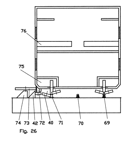
Fig. 26 shows how comfortable and roomy a carriage will be on broad gauge
railway.
Fig. 27 shows how cardules is steered by not carrying steer wheels with
flanges on
the inner side of the rails.
Fig. 28 shows how a double-rotor motor can drive the steer and drive wheels
and
how they by means of eccentric axes are pressed together against the rail.
Fig. 29 shows double-rotor motor inside a wheel is driven by DC supply via
brushes in the axis center.
Fig. 30 shows a pole shoe of folded bands. Such pole shoes are placed between
two rolls of band with windings.
Fig. 31 shows elements with pole shoes of folded and bent bands are placed in
a
row with the pole shoes side by side.
Fig. 32 shows how cardules and steer and driving wheels are sitting displaced
on
a track with standard gauge.
Fig. 33 shows a train with three carriages where the cardules in the ends are
completely steered by steer and drive wheels while the cardules between the
carriages are steered to its location laterally by steer and drive wheels and
to its
angle by the half angle between the cars.
Fig. 34 shows steer and drive wheels, which have almost horizontal axes and
flanges, but no carrying load surface.
Fig. 35 shows boggy with cardules, which have steer and drive wheels. They run
against the side of the rails, which are allowed to have variable gauge.
Mechanism
CA 02790120 2012-08-16
WO 2011/112134 PCT/SE2011/000029
keeps the carriage between the cardules.
Description
The basic geometric form of the rolling is that the front - rear axis and the
wheel
5 axis intersect and that the wheel carrying surface is a part of a sphere,
which is the
case on Fig. 1. A cardule is shown in Fig. 2 with a rail 1 on which there run
a
wheel 2 with the axis 3 in a square cardan ring 4 suspended in front and rear
mounts 5 with front-rear axis 6. The mounts are in the cardule holder 7.
The steering is not needed to be very just. If a side wind presses the
carriage the
wheel will tilt slightly around the cardule front-rear axis, which is close to
the center
of gravity of the wheel, which thus tilt easiest and making the cross friction
force
negligible. The rectangular cardan ring has so low weight that the bending
forces
on the wheel axis will not be appreciable.
The driving will also be flexible. The cardule is well suited to drive. The
friction
force, which goes forward or backward can be maximally exploited because no
cross forces exist.
A cardule where axis and wheel change place is shown in Fig. 2 A. An axis 8
has
hole with bearings for a front rear axis 9, which sit in the inner ring 10 on
a bearing
for the inner ring 10 on a bearing for the wheel 11, which run on the rail. In
order to
adjust the gait the front-rear axis can be placed other than in the diameter.
On Fig. 3 is shown a driving containing cylindrical steer wheels 12, 13 which
roll
correct against plane sides on the rail head. The steer wheels are mounted on
a
ring 14 with axis 15 in the carriage body. The steer wheels can also be made
conical as in Fig. 4. With the steer wheels 16, 17 driving, the possibility
arise to
sometimes not let them press against the rail 1, but also to apply the force,
which
is needed for wanted acceleration and primary run ascent and securely slow
down
by the returning of the breaking effect.
CA 02790120 2012-08-16
WO 2011/112134 PCT/SE2011/000029
6
Wheel against the rib 18 is easy to apply as in Fig. 5A. This however claim
that
this steering and driving wheels are given an horizontal movement before they
are
lifted in order to pass railectors with fixed seamless rails, which can be
used when
no flanges are on the carrying wheels. The rib must be smooth and preferably
with
uniform thickness to make a steel wheel roll well.
Wheels with solid rubber have fewer demands and can be useful because they
wear modest claims when used with heavy pressure only when running on hills
and are accelerating. The rails have better be lifted for the steering wheels
to run
freely.
The rail rib can by superstructures be made thicker as in Fig. 5A by e.g. a
square
bar 19, a not symmetrical U-bar or a square tube. Then a wheel can run against
the rail head sides on plane tracks, but in hills with wheels with strong
pressure
against superstructures.
The rail can be completed in different ways. With flat bars 20 from under the
head
down to the foot as in Fig. 5B the contact surface to the drive wheels can be
many
times larger. Wheels with rubber coating can also here be used. The cross
forces
in the contact surface will be negligible, making the bending forces in the
axes
also negligible. This keeps the weight of the wheels down.
The flat bars can be fixed in the foot but with a slot to the head, making it
possible
to fill the space wit concrete 21 and then be closed.
Bracing 22 with flat bar as in Fig. 5C can also be used. There is known also
how
the rail UIC60 and the foot and a portion 23 of the rib from the rail SJ43 can
be put
together to ra all which withstand great pressure from the drive wheels. Rails
for
industry tracks need as a rule not be very precise made as the speed often is
low
there. The superstructures on the rails make them stiffer, which increases the
buoyancy
CA 02790120 2012-08-16
WO 2011/112134 PCT/SE2011/000029
7
With cardules running on the head it is an advantage if it is flat and wide.
This can
be made with a superstructure 24 as in Fig. 6. The super head can get tilted
sides
making the steer and drive wheels cylindrical when their axes are not
vertical.
The super head can reach down to the foot as in Fig. 7, so that broad drive
wheels
26 can be used and give increased drive forces. The sides can be braced with
crimped coarse plate 27 and concrete. The rails construction can get increased
buoyancy, so that shorter trains with heavier carriages can be used.
The superstructure on Fig. 7 can be used also with vertical sides. Of cause
cog-
wheel driving shall not be ignored. The function will probably be better on
rails with
driving on the sides. The cog-wheel shall probably have an axis of its own and
down shift because when it is to be used the driving is heavy. The cog- wheels
should be protected when not used.
New rails can be made rectangular and with trapeze form 29. They can reach the
extreme form of being solid 30. Variants are shown in 8, 9 and 10.
Now when steeper hills can be managed, old lines can be straightened and new
lines made straighter. This is a new Principe of building railways where the
parts of
the tracks will be built for those driving forces which are required and the
driving
wheels is activated where the driving forces are needed. If the rails are
soiled so
that slipping occurs, then the pressure on the driving wheels will be
increased. Old
lines can be used and new lines can go where one wish without worrying much
for
hills. This reduces intrusion into natural and built consent.
Now when the load-carrying wheels have no flanges the rails in the railectors,
which are switches for the use steering wheels, can be made without joints as
in
Fig. 11 and 12. The flank rails 32 along the railectors outside the outer
rails keep
the carriages within the railectors. The other steering wheels will be lifted
or forced
up. The rails 33 in the railector need not be made pointy, but the end will
have a
sloop.
CA 02790120 2012-08-16
WO 2011/112134 PCT/SE2011/000029
8
A railector with a boggy down under a carriage is shown in cut in Fig. 13. On
the
rail 1 a carriage is buried by cardules 2. The steering and driving wheels 16,
17
are in position for ralect to the left. A flank left wheel 34 is driven with a
gear 35
against the railector left flank rail 32. The steer and drive wheels can be
pressed
together with wires 36, 37 between their hubs.
How the railectors can be implemented in steps is shown in Fig. 14 to 19. The
position at which the description of the railector will be made corresponds
about
Fig. 17. In Fig. 14 shows classical steering between the rail heads with the
inner
steer wheels 38 and 39.
The squares are rails, horizontal rectangles are steer wheels, hatched
horizontal
rectangles are flank wheels and vertical rectangles are flank left rail or
flank right
rail or two railector flank rails. When two tracks shall go together to a
single track
the outer rails outer sides will be free from branching. In Fig. 15 a left
outer steer
wheel 40 has gone down together with the left flank wheel 41. At the right
rail the
left steer wheel 39 goes up. This is initiated by the signal systems, witch
start
lifting mechanisms, but which otherwise will be automatically performed by
ramp
up to the plane surface of the railector area, which has the same level as
that of
the top of the rails.
In Fig. 16 the boggy reach the flank rails. The left flank rail 42 is
affecting the flank
wheel 41, so that the steer wheel 40 is tight to the left rail. The right
flank rail 43
goes free. Then the right steer wheel 38 can be lifted as in Fig. 17 so that
it goes
free over the railector area.
The signal system detects when the railector area is passed and press down the
nearest inner steer wheel 38 shown in Fig. 18. After this the steer wheel 39
goes
down and at last the steer wheel 40 with flank wheel 41 goes up as shown in
Fig.
19.
CA 02790120 2012-08-16
WO 2011/112134 PCT/SE2011/000029
9
One option is that the right flank rail 43 has a slopping roof as in Fig, 18,
which
can press down the flank wheel 45 and thus the steer wheel 44 as in Fig. 19,
if the
signal system has not before done this. Then the steer wheel 39 goes down and
the steer wheel 44 goes up if one want to go back to the initial state. Sins
the rails
in the railector area are fixed and has no joints it can be made for how large
curvature radius as any. This railector is thus suitable for very fast trains.
When wheel pairs with intermediate shaft are not used the floor can be lowered
allowing for two floors. The thick strong hubs need not be used in the
cardules.
Other wheels which do not take up the cross forces are shown in Fig. 20 to 24.
A
truncated ball 46 on a truncated sphere 47 on an axis 48 as in Fig. 20 is a
wheel
which has no forces transversely when it rolls. It can get some elasticity by
making
a ring slot with rubber ring 49 and on this a ring 50 on which the truncated
sphere
47 sits carried on its inner broader ring slot followed with elastic material
51 to the
sides of the inner slot, which has tightening rings 52.
Depending on the operating conditions spokes and the corresponding part will
be
so week that they allow cross movements. Totally fabulous materials are in the
pipeline.
Truncated cone-like rolls partly inside each other in a ring as in the cross-
section
in Fig. 21 give a wheel without lateral forces when they roll. The rolls have
bearings 54 in one to the rolls customized ring 55, which continue with spokes
56
going to the hub 57. The wheel sides look like the Fig. 22.
A similar wheel with alternately big 58 and small rolls 59 partly within each
other
are in Fig. 23. They have the axes 60 and 61, which are going to the hub 62.
A wheel, which slide on an axis take up very small side forces, but need a
side
way fixing of the axis and also a controlled turning round a vertical axis to
be
useful. On Fig. 24 there are two bearings 63 and 64 in which there is an axis
65
CA 02790120 2012-08-16
WO 2011/112134 PCT/SE2011/000029
with a wheel 66. The wheel has a kind of tire 67 of a thin ring which can be
deformed a little so that it can lie flat against the ground or rail. The tire
lies and is
steered 68 in a low greased grove.
5 The next step in the improvement is to increase the width of the carriage to
appropriate dimensions. The gauge affects the economy in all parts, the
comfort
and the adaptation to its purpose of the passenger carriage. Also goods-wagons
are to narrow, which was realized from Swedish Patent Gazette first page 1981-
08-10. The drawing is shown in Fig. 25 with conventional length.
There are machines, which maintain lines in a very effectively and fast way.
This
depends among other things on the fact that rails are in place. Thus lines can
easily be made broader to double gauge with machines, which run on the
existing
rails. The chose of gauge will of cause be a popular 2W generation that is to
say
the two rails 69, 70 will be left so that one rail will go in the middle
between a
broad standard line to the rail 71 as in Fig. 26. The carriage runs in a
railector to
the left with the steering wheel 40 down, but the left flank wheel 72 is
freely
rotating or has a motor of its own, which only needs to manage the friction
when a
railector passes. The left flank wheel runs against the flank rail 42. The
steering
can alternatively be made with the railector wheel 73, which is on a flank
foundation 74 on the side of the railector.
With a wheel house 75 in the carriage the floor will be reach the level of the
platform and the doors between the carriages will get a lot of space. Two
floors
can easily be used without making the carriage non stabile. Two beds 76 on the
cross get space between the outer walls. If the carriage is divided in half
and
passage is in the first floor then two rooms, well sound isolated, can be
packed
with beds. 18 beds in the length will fit in the cross-section.
If the load is ore the middle rail could be left so that further wheels could
carry the
weight. That wheels need to resist taking up cross forces, even if the outer
wheels
have flanges. Because the wheels with flanges are cone shaped, the roll
diameter
CA 02790120 2012-08-16
WO 2011/112134 PCT/SE2011/000029
11
varies and thus the middle wheel shall roll freely.
Old carriages with standard gauge can also run on a track with new rails. Now
the
transition to 2W can be made in steps during a long period. Fig. 27 show two
cardules 2 and four flange cones 78 attached with bearings 79, 80 in a boggy
frame 77 and two cardule holders 7 with brackets also for the front-rear axes,
which can be assembled to run in regular switches and during a transition
period.
Cars can easily run crosswise into a wide carriage.
Carriages can have sleeping compartments on both sides of a corridor with
light
from the ceiling. Berths get space in all day carriages. When one also can get
space for three floors one realizes that the trains will be short, stabile and
with
small air drag.
With flexible wheel system and sand in the rails the train will run calm and
quit
from e.g. coast to coast.
In a trapeze rail magnetic force can be used to pull the wheels against the
rails. In
Fig. 8 the side surfaces are partly made of nonmagnetic material e.g.
stainless
nonmagnetic steel. A DC current in a wire inside the trapeze rail drive a
magnetic
field which goes round and strongly through iron wheels.
The electric motor can be made with lower weight. That which normally is the
stator gives bearings in a new housing and is allowed to rotate in the
opposite
direction as the rotor. The new tube formed axis will be provided with slip
rings for
3-phase AC or DC voltage. The axis can go to a gear where the rotation
direction
of the one axis will be changed and the torque performed from one axis.
Concerning the steer and drive wheels 16, 17 which rotate in different
directions is
the using natural e.g. as in Fig. 28. An electric motor 81 has the rotor axis
going to
a simple gear 82, which drives the one drive wheel 17. That which normally is
the
stator has bearings allowing it to rotate in the opposite direction goes to a
conical
CA 02790120 2012-08-16
WO 2011/112134 PCT/SE2011/000029
12
cog-wheel in a second simple gear 83, which drives the other drive wheel 16.
The
bearings of the drive wheels 84, 85 are interconnected with arms 86, 87 and
eccentric pin 88 in the arms, so that the driving wheels can be pressed
against the
sides of a rail 1. The hidden axis 89 shall perhaps be used for the driving of
a
cardule from the same motor.
The cardule can have a motor inside the wheel, as in Fig. 29 where also an
inverter and a planetary gear is used. Brushes 90 are in the center of and
from
each end in a tube formed axis 91 with another brush against a small ring a 3-
phase voltage can be entered directly to the motor. From the collectors 92
wires
go out to the converter 93 inside the rotor 94. On the rotor there are a
winding 95,
which feeds with the 3-phase voltage. The rotor has also inner cog-wheels 96
to a
planetary gear. The planet wheels 97 are attached to a disc 98 on a tube axis
99,
which sits on the bearing 100 on the tube formed axis 91, which outside has a
flange 101 for the attached to a not shown cardan ring 4. On the opposite side
sits
only a tube formed axes 102 with flanges 103.
The outer cog-wheel 104 of the planetary gear sits inside the cardule wheel 2
whose sides are carried on the tube axis 99, 102.
When the DC voltage will be delivered to the rotor winding, this generate a
circulating magnetic field. This drives the rotor in one direction and the
wheel in
the opposite direction. The Coriolis forces can with the rotation in different
directions be balanced to tilt the cardule in the curves.
Of cause one shall not forget magnetic forces. The transmission of the
magnetic
field to a motor from the ground to the train can be effective with large pole-
shoes
as in Fig. 30 and 31. When the electro-plate is folded in the top of the pole-
shoe
with a radius, which is larger than the plate thickness the magnetic field is
spread
out in the air gap so that the magnetic resistance in corresponding degree
decreases without an increase of the pole-shoe weight.
CA 02790120 2012-08-16
WO 2011/112134 PCT/SE2011/000029
13
Fig. 30 shows a pole-shoe of band folded to a trapeze formed pack with rounded
folds. The pack is squished in a center part. The ends are bent upwards to a
pole-
shoe with straight top 105. These pole-shoes are between rolls 106 of band
with
windings 107 on.
Fig. 31 shows pole-shoe of band folded to long trapeze formed pack with
rounded
folds. The pack is bent on two places 108, 109 with the ends upturned to
straight
tops 110. A number of these U-formed cores are laid in a row with the poles
side
by side.
If a cardule on an existing line with standard gauge is used then the wheels
under
a carriage can lock like Fig. 32 in a train with the speed which now can be
reached. Against the left rail 1 there are a pair of steer wheels 16, 17. In
front of
them the wheels is shown in the cardule. In front of this is a pair of steer
and drive
wheels. The right rail has its steer and drive wheel opposite to the left
cardule etc.
The steer wheels has namely I m diameter why they can't sit opposite on the
rails
without being displaced. From 2 conventional wheels with flanges to 2 cardules
and 8 steer and drive wheels, at lest 5 times greater driving force can be
achieved.
The comparison can be made with a usual boggy between carriages with 4 wheels
or two bogies with 8 wheels, but the weight is distributed between the wheels,
so
that the total drive forces is unchanged. The steer and drive wheels can
however
be pressed against the rail as strong as one like.
On Fig. 33 is shown the wheels in a train with three carriages and the double
gauge. Those cardules 201, 202 which are sitting in the ends are steered to
their
direction and position by the four steer wheels 203. The cardules 204 between
the
carriages are steered to their direction by changing direction with half the
angle
between the surrounding carriages. This can be achieved with a number of
mechanisms. The cardule positions are steered by the two steer wheels 205.
There the driving force can be increased 3 times.
CA 02790120 2012-08-16
WO 2011/112134 PCT/SE2011/000029
14
How roomy it will be is shown by the fact that there is space for double doors
206
between the carriages. A flank rail 32 and a flank wheel 34 are also shown.
The permanent problem for the railway is the rigid gauge. The consequences are
many. Different gauge arose, causing factories to build many types of
carriages,
passenger to change train and goods to be reloaded. It is of cause costly to
rebuild lines to standard gauge. The carriages are as a rule made only for one
gauge, but it has become necessary to make carriages for a couple of gauges.
The use of the cardule makes it possible to give the carriage a limited
lateral
movement. The cardule can be steered with wheels with flanges on booth sides
and be more or less or not carrying. With locked gauge between the wheels an
outer flange can be lifted when passing old switches. Optionally the switches
can
be built for double flanges.
The steering of the cardule, but also ordinary wheels can be helped up hills.
This
can be done as in Fig. 34 with two wheels 301 and 302 with outwards tilted
axes
303, 304 without bearing surfaces on both sides of the rail, but with wheel
flanges
305, which with bearings 306, 307 and devices 308, 309 are pressed against the
sides on the rail heads 310. It will not be perfect rolling. With carry
devices where
left and right wheel system (cardule and steer wheel or steer magnets) are
steered
by its rail the wheel system can be allowed to run in a different direction
and on
different distances from each other.
The advantage with this is that the trains can change gauge without hinder,
but
also that the gauge can be adapted to the situation. For preventing the trains
to
roll over inwards in steep curves with high superelevation when the sped is
low
and not roll over outwards when the speed is high the gauge can be increased.
With cardules the problem has its solution by increasing the gauge only in the
CA 02790120 2012-08-16
WO 2011/112134 PCT/SE2011/000029
curves. Where the ground is clay the embankment can be broadened, the sleepers
extended and the gauge increased to make the track harder. New lines can be
built with broad gauge and with broader carriages, which give better comfort
and
more effective use of the materials.
5
In Fig. 35 is shown a boggy with a cardule 8 running on the left rail 1. On
the right
rail is a cardule 320 running with otherwise the same parts as on the left
wheel,
but mirrored on the right rail 321, which not need be parallel with the left
rail 1.
10 The cardule 8 is steered with two front steer wheels and two rear steer
wheels 16,
17 against the sides of the rail head, which can have extra height.
The steer wheels can be replaced with steer magnets. There profiles can be
used,
which correspond to the flanges on the usual wheels, so that they can run on
15 ordinary switches. The steering can also be driven in e.g. hills where a
linear
motor together with the rails will be made and provided with electric energy
preferable in magnets in the rails.
When also the steer wheels are driving they will be forced together with great
force from e.g. wires, which lie on sheaves on the steer wheel axes, so that
blocks
in tackles are achieved. The wires are bent to follow the steer wheel sides
and put
the pressure of the wheel arms 86, 87 on the rail head sides.
The cardule axis with bracket sits in a broad left cross bar 322. The steer
wheels
are also brought together with cardule holder 323 to the left cross bar 322.
From the right cardule 320 is the right cross bar 324 coming.
The connection of the cross bars 322, 324 to the carriage can be made on many
ways. Here this is illustrated with the slipping of the left cross bar 322
over the
right crossbar 324. They have an elongated hole where a center axis 325 goes
to
the carriages marked with the beams 326, 327. They are kept together while the
CA 02790120 2012-08-16
WO 2011/112134 PCT/SE2011/000029
16
steer wheels move them side wards when the rails have varying gauge along the
line.
In order to make the drawings readable the center parts have been made small,
but in the reality they shall go the way out to the cardules to withstand the
load
with reasonable dimensions. The beam 326 is drawn translucent around the
center
axis 325. The cardule is here of the type with front-rear axis inside the
bearings
and a cardan bearing in the middle on the front-rear axis inside a cross axis.