Note: Descriptions are shown in the official language in which they were submitted.
CA 02790204 2012-08-17
WO 2011/102985 PCT/US2011/023889
MODULAR MEDICAL FLUID HEATING APPARATUS
Related Applications
This application is a continuation of U.S. Application No. 12/891,463, filed
on September 27, 2010, which claims priority to and the benefit of U.S.
Provisional
Application No. 61/305,377, filed on February 17, 2010, the entire contents of
each
of which are hereby incorporated by reference herein.
Field of the Invention
The invention relates generally to a medical fluid dispensing apparatus and
more specifically to a medical fluid heater for intravenous dispensing.
Background of the Invention
Patients requiring an intravenous administration of fluids, be it blood,
plasma, plasma extenders or other high volume medications stand the chance of
becoming hypothermic if the fluid, which is usually refrigerated or at most at
room
temperature, is administered without heating. This is especially critical when
intravenous administration takes place in the field, away from a controlled
environment such as a hospital, or when delivering fluids to children or
critical care
patients.
Additionally, the amount of fluid needing to be administered and the rate of
administration need to be matched to the heating device. Available heating
devices
are typically fixed in size and do not allow for such matching.
The present invention addresses these issues.
Brief Description of the Drawings
The objects and features of the invention can be understood more completely
by referring to the drawings described below and the accompanying
descriptions.
Fig. 1 is a block diagram of an embodiment of a dispensing device
constructed in accordance with an illustrative embodiment of the invention;
1
CA 02790204 2012-08-17
WO 2011/102985 PCTIUS2011/023889
Fig. 2 is a schematic diagram of a general embodiment of a heating module
of the dispensing device shown in Fig. 1;
Fig. 3 is a schematic diagram of the embodiment of the device shown in Fig.
1; and
Fig. 4 is a perspective view of various heating module components arranged
so as to have a 3-D fluid path.
Summary of the Invention
The invention relates to medical fluid infusion warmer technology such as
used for blood, IV fluid, volume medicaments and nutrients (generally referred
to as
medical fluids) that is easily integrated with existing medical systems and is
capable
of utilizing multiple power sources (including fuel cells). In addition the
system has
a reduced weight and size form factor that is suitable for forward combat
operations. The invention includes, in one embodiment, a controller and a
plurality
of concatenated heating modules in electrical communication with the
controller.
The controller controls the flow of current to the plurality of heating
modules in
response to temperature measurements from at least one of the plurality of
heating
modules. In one embodiment, each of the plurality of heating modules
concatenated
with another heating module is connected by Luer-Lok TM connectors. In another
embodiment the modular medical fluid heating system further includes an
auxiliary
heating unit in electrical communication with the controller and in close
physical
juxtaposition with the plurality of heating modules.
In another aspect, the invention relates to a heating module for a modular
medical fluid heating system including a fluid input port; a fluid output
port; and a
serpentine tube through which fluid passes from the fluid input port to the
fluid
output port. The heating module can be concatenated with other heating modules
to
form a longer fluid path. In one embodiment the fluid input port and the fluid
output
port include Luer-LokTM connectors.
In another aspect the invention relates to a method of heating a medical fluid
comprising the steps of : providing a system comprising: a controller; and a
plurality
of concatenated heating modules in electrical communication with the
controller,
each heating module comprising a tube and a heating element along the tube,
and an
2
CA 02790204 2012-08-17
WO 2011/102985 PCT/US2011/023889
input port and an output port; and connecting an input port of a first heating
module
of said plurality of heating modules to a medical fluid supply; and connecting
an
intravenous needle to the output port of a last heating module of said
plurality of
heating modules. In one embodiment the controller controls a flow of current
to the
plurality of heating modules in response to temperature measurements from at
least
one of the plurality of heating modules. In another embodiment the method
further
comprises the step of adding additional heating modules to the plurality of
heating
modules if additional heating is required.
Description of a Preferred Embodiment
In brief overview and referring to Fig. 1, a fluid heating system 10
constructed in accordance with the invention includes a controller 14, a
plurality of
heating modules 18, 18' (generally 18) and a portable power supply 22. In one
embodiment, the system 10 also includes an optional auxiliary heating unit 26.
The portable power supply 22, such as a battery, is connected to controller
14. The power supply can be, without limitation, a fuel cell, a standard
battery, a
lithium ion battery, a solar cell, a lead acid battery suitable for supplying
power to a
vehicle, or the vehicle power itself. In addition the power supply source can
be an
AC source. The controller 14 is, in turn, connected to the heating modules 18
which
are concatenated in a daisy-chain or otherwise linked or connected together. A
fluid
reservoir 30, such as an IV bag, is attached to the input port of the first of
the series
of heating modules 18 by way of a Luer-LokTM connector. An intravenous needle
assembly is attached to the output port of the last heating module 18' of the
series of
modules which are in fluid communication with each other. Although this
embodiment is described in terms of Luer-LokTM, connectors any removable
connector can be used.
Fluid which moves from the reservoir 30 through the heating modules 18 is
heated by internal electrically energized coils or resistive elements located
within the
module 18. Although internal electrically energized coils or resistive
elements are
described herein, any suitable heating element can be used. The temperature of
the
fluid is monitored as it passes through the series of modules 18. The
temperature of
the fluid is regulated by the controller 14 by controlling the amount of
current
3
CA 02790204 2012-08-17
WO 2011/102985 PCTIUS2011/023889
passing from the power supply 22 to the heating coils of the module 18 in
response
to thermal detectors located along the fluid path within the heating module
18. In
the embodiment shown, a heating module 18 may be concatenated or otherwise
connected with other heating modules 18 to form a longer fluid path or may be
used
individually. These heating modules may be disposable. Fluid leaving the last
heating module 18 passes through the needle set to the intravenous needle 34.
Although this embodiment depicts a series of serpentine cylindrical tubes, the
fluid
path may be constructed as any shaped conduit or a conduit having any cross-
sectional shape, including but not limited to elliptical or rectangular,
provided there
is a large enough surface area to volume ratio. Without the loss of generality
the
terms tube and conduit are used interchangeably to describe any of these
conduit
configurations.
In one embodiment, the system includes an optional auxiliary heating
module 26. This heating module 26, in one embodiment, uses a combustible fuel
source, such as methanol, to provide the thermal energy for heating the fluid.
When
the auxiliary heating module 26 is used, the portable power supply 22 is not
used
and can be disconnected from the circuit. In such an embodiment, an integral
battery in the controller 14 powers the controller 14.
The auxiliary heating module 26, when in use, is positioned adjacent the
heating module 18 and heat from the auxiliary heating module 26 passes through
the
wall of the heating module 18 and heats the fluid path of the heating module
18 by
conduction. The auxiliary heating unit 26 is electrically connected 20 to the
controller 14, which monitors the temperature of the fluid exiting the heating
module
18 and controls the combustion in the auxiliary heating unit 26 by providing
temperature data to the auxiliary heating unit 26 as a control system input.
Referring to Fig. 2, each heating module 18 includes a fluid input port 40 and
a fluid output port 44. In one embodiment, the fluid ports 40, 44 are female
and
male Luer-Lok TM connectors, respectively. In other embodiments, the heating
modules are connected by way of compression o-rings. The two ports are
connected
by a serpentine tube 48 through which fluid passes from the input port 40 to
the
output port 44. The serpentine tube 48 in one embodiment has a serpentine
heating
coil 49 arranged along the length of the tube. A thermal detector 50, such as
a
4
CA 02790204 2012-08-17
WO 2011/102985 PCT/US2011/023889
thermistor, is in, adjacent to, or along the fluid path to measure the
temperature of
the fluid. In one embodiment, the heating coil 49 is positioned on one side of
the
metallic tube 48. This allows the auxiliary heating apparatus to be attached
to the
other side of the tube 48 so as to heat the metallic tube 48 and not the coils
49.
The thermal detector 50 and the heating coil 49 are connected to the
controller 14 through a multi-pin connector 54. A second multi-pin connector
58
provides electrical connections to and from the controller 14 for the next
heating
module 18 in the concatenated or series configuration.
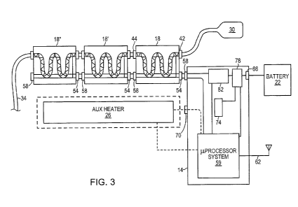
Referring to Fig. 3, in more detail, the controller 14 includes a
microprocessor system 59. The microprocessor system 59 includes one or more of
a
ROM program memory, RAM memory, and A/D converter, a D/A converter, serial
ports, parallel ports, and a wireless transceiver with antenna 62. The
controller 14
also includes a connector 58 to communicate with the heating modules 18. A
power
connector 66 connects the power source 22 to the controller 14. A third
connector
70 provides temperature information from the controller 14 to the auxiliary
heating
unit 26. The controller 14 also includes an internal battery 74 to supply
power to the
microprocessor system 59 when there is no external battery 22. Both the
external
power supply 22 and the internal battery 74 are connected to a power control
switch
78, which disconnects the microprocessor system 59 from, the internal battery
74
when the external power supply 22 is connected to the controller 14.
A power switch unit 82 which is controlled by the microprocessor system 59
connects the heating coils 49 of the heating module 18 to the power supply 22.
In
one embodiment, the power switch 82 is controlled by certain bits from the
parallel
port of the microprocessor system 59 in response to temperature data from at
least
one of the thermal detectors 50 (see Fig. 2) by the A/D converter of the
microprocessor system 59. In one embodiment, temperature data is provided to
the
auxiliary heater by the D/A converter of the microprocessor system 59. It
should
also be noted that nothing constrains the fluid flow to three modules which is
provided as exemplary only. Thus, the modules can be extended linearly.
Although the system has been described in terms of a linear concatenation of
heating modules, Fig. 4 discloses an equivalent system for forming adjustable
fluid
flow. In such a system heating modules are connected so as to have a
continuous
5
CA 02790204 2012-08-17
WO 2011/102985 PCT/US2011/023889
fluid path in three dimensions from the input first heating module to the
twenty-
seventh output heating module. The electrical connections are also continuous
from
the first heating module to the twenty seventh heating module. It should also
be
noted that nothing constrains the fluid flow to twenty seven modules which is
provided as exemplary only. Thus, not only can the modules be extended
linearly,
but also on three dimensions.
The examples presented herein are intended to illustrate potential and
specific implementations of the invention. It can be appreciated that the
examples
are intended primarily for purposes of illustration of the invention for those
skilled
in the art. There may be variations to these diagrams or the operations
described
herein without departing from the spirit of the invention. For instance, in
certain
cases, method steps or operations may be performed or executed in differing
order,
or operations may be added, deleted or modified.
Variations, modification, and other implementations of what is described
herein will occur to those of ordinary skill in the art without departing from
the spirit
and scope of the invention as claimed. Accordingly, the invention is to be
defined
not by the preceding illustrative description, but instead by the spirit and
scope of
the following claims.
What is claimed is:
6