Note: Descriptions are shown in the official language in which they were submitted.
CA 02790423 2012-08-17
WO 2011/103410 PCT/US2011/025415
HEAT FINS AND RELATED SYSTEMS AND METHODS
CROSS REFERENCE TO RELEATED APPLICATION
[001] For purposes of the U.S., the present application is a U.S.
nonprovisional patent
application of, and claims priority under 35 U.S.C. 119(e) to, U.S.
provisional patent
application serial number 61/306,233, filed February 19, 2010. This
provisional patent
application is hereby incorporated herein by reference.
COPYRIGHT STATEMENT
[002] All of the material in this patent document is subject to copyright
protection under
the copyright laws of the United States and other countries. The copyright
owner has no
objection to the facsimile reproduction by anyone of the patent document or
the patent
disclosure, as it appears in official governmental records but, otherwise, all
other copyright
rights whatsoever are reserved.
BACKGROUND OF THE INVENTION
[003] The present invention generally relates to providing heat to product
stored in large
scale containers.
[004] Large scale containers, such as, for example, tanks, vessels and drums,
are often used
by processing plants to hold liquids needed for processing, storage and/or
resale. Plants
which process or store water, solvents, additives, chemicals, petrochemicals,
crude oil,
asphalt or edible oils commonly use such containers. Many of these products
require
additional heat to prevent the product inside the container from freezing or
to keep the
product below a certain viscosity.
[005] There are several methods used to add heat to product inside a vessel.
One such
method utilizes internal heating coils, sometimes referred to simply as
internal coils.
[006] Such an internal coil may comprise a small diameter pipe (2" to 3")
installed along the
bottom (and sometimes the sides) of a vessel or tank. A heating medium, such
as, for
example, steam, hot water or hot oil, flows through the pipe, thereby causing
the pipe to act
as a heating element. The heating medium has a higher temperature than the
process inside
the tank, thereby creating a temperature difference.
[007] Heat transfer from the heating medium to the process can be determined
using the
equation Q = UAdT, where Q is the heat transfer from the heating medium to the
process, U
is the overall heat transfer coefficient from the heating medium to the
process, A is the total
CA 02790423 2012-08-17
WO 2011/103410 PCT/US2011/025415
2
surface area of the heating medium against the process, and dT is the
difference in
temperature between the heating medium and the process. This equation allows
one to
calculate how much heat energy is transferred from the heating medium into the
process for
any application.
[008] Typically, the goal would be to add enough heat into the process so as
to replace heat
that is lost through:
= the tank walls and insulation;
= the bottom of the tank into the earth; and
= the air space atop the process (but inside the tank) through the roof wall
and then
through the insulation.
[009] Internal heating coils are commonly utilized in large vessels such as,
for example,
asphalt tanks, heavy crude oil tanks, vacuum bottom tanks and No. 6 fuel oil
tanks, because:
= the product (e.g. crude oil) is normally not completely unsalvageable if the
heating
medium leaks into the product;
= the product's temperature range is not normally small; and
= it is very straightforward to design and maximize surface area (A), for
example by
installing additional footage of pipe, because the heat transfer from the
heating
medium to the product (Q), the overall heat transfer coefficient from the
heating
medium to the product (U), and the difference in temperature between the
heating
medium and the product (dT) are all known.
[010] One potential problem, specifically when using internal coils to heat
petroleum-based
products inside tanks, is that these products (asphalt, coker feeds, vacuum
residues and No.
6 fuel oil) may solidify on the outside of the internal coils over time. This
process is
commonly known as "coking". When product "cooks" on the outside wall of an
internal coil,
it adheres to the outside of the internal coil and leaves a heavy residue that
will not naturally
dissipate. This presents two problems.
[011] First, the cooked on material hinders heat transfer from the heating
medium to the
process because it has very poor thermal conductivity, as it is comprised of
mostly carbon.
So, the thermal performance of the coil is diminished over time as the layer
grows and
eventually requires total replacement of the coil.
[012] Second, the cooked on material is very costly to remove from the coil
during
scheduled cleaning. Hydro-blasting is the typical method of cleaning such
cooked on
material off of a coil, and this can be very costly.
CA 02790423 2012-08-17
WO 2011/103410 PCT/US2011/025415
3
[013] A need exists for improvement in providing heat to product stored in
large scale
containers. This, and other needs, are addressed by one or more aspects of the
present
invention.
SUMMARY OF THE INVENTION
[014] The present invention includes many aspects and features. Moreover,
while many
aspects and features relate to, and are described in, the context of providing
heat to product
stored in large scale containers, the present invention is not limited to use
only in this
context, as will become apparent from the following summaries and detailed
descriptions of
aspects, features, and one or more embodiments of the present invention.
[015] One aspect of the present invention relates to a heat fin. The heat fin
includes first
and second halves, each half comprising a curved portion configured to
partially surround a
pipe, and a plurality of planar portions spaced generally evenly from one
another, each planar
portion extending outwardly from the curved portion. Each of the plurality of
planar
portions generally runs along the entire length of the respective half it is
part of. The first
and second halves are configured to be bolted to one another around a pipe.
[016] In a feature of this aspect of the invention, the heat fin was extruded.
[017] In a feature of this aspect of the invention, the heat fin comprises
aluminum.
[018] In a feature of this aspect of the invention, the heat fin comprises
carbon steel.
[019] In a feature of this aspect of the invention, the heat fin comprises
stainless steel.
[020] In a feature of this aspect of the invention, the heat fin comprises a
silicon-based
compound.
[021] In a feature of this aspect of the invention, the heat fin comprises a
graphite-based
compound.
[022] In a feature of this aspect of the invention, the heat fin comprises a
high-conductivity
polymer.
[023] In a feature of this aspect of the invention, the heat fin is forty feet
long.
[024] In a feature of this aspect of the invention, the heat fin is nine feet
and six inches long.
[025] Another aspect of the present invention relates to a heat fin. The heat
fin includes
first and second halves, each half comprising a curved portion configured to
partially
surround a pipe, and a plurality of planar portions spaced generally evenly
from one another,
each planar portion extending outwardly from the curved portion in a direction
generally
perpendicular to a line tangential to the curved portion at the point that
planar portion joins
the curved portion. Each of the plurality of planar portions generally runs
along the entire
CA 02790423 2012-08-17
WO 2011/103410 PCT/US2011/025415
4
length of the respective half it is part of. The first and second halves are
configured to be
bolted to one another around a pipe.
[026] Another aspect of the present invention relates to a system. The system
includes an
internal coil having a heating medium flowing therethrough, and a heat fin
secured to the
internal coil. The heat fin includes first and second halves, each half
comprising a curved
portion configured to partially surround the internal coil, and a plurality of
planar portions
spaced generally evenly from one another, each planar portion extending
outwardly from the
curved portion. Each of the plurality of planar portions generally runs along
the entire length
of the respective half it is part of. The first and second halves are bolted
to one another
around the internal coil. The heat fin is configured to increase heat transfer
from the heating
medium flowing through the internal coil into product contained in a large
scale container.
[027] Another aspect of the present invention relates to a system. The system
includes a
large scale container having product contained therein, an internal coil
within the large scale
container having a heating medium flowing therethrough, and a heat fin secured
to the
internal coil. The heat fin includes first and second halves, each half
comprising a curved
portion configured to partially surround the internal coil, and a plurality of
planar portions
spaced generally evenly from one another, each planar portion extending
outwardly from the
curved portion. Each of the plurality of planar portions generally runs along
the entire length
of the respective half it is part of. The first and second halves are bolted
to one another
around the internal coil. The heat fin increases heat transfer from the
heating medium
flowing through the internal coil into the product contained in the large
scale container.
[028] Another aspect of the present invention relates to a system. The system
includes an
internal coil having a heating medium flowing therethrough, and a heat fin
secured to the
internal coil. The heat fin includes first and second halves, each half
comprising a curved
portion configured to partially surround the internal coil, and a plurality of
planar portions
spaced generally evenly from one another, each planar portion extending
outwardly from the
curved portion. Each of the plurality of planar portions generally runs along
the entire length
of the respective half it is part of. The first and second halves are bolted
to one another
around the internal coil. A heat transfer compound is disposed in one or more
gaps between
the internal coil and the heat fin. The heat fin is configured to increase
heat transfer from the
heating medium flowing through the internal coil into product contained in a
large scale
container.
[029] Another aspect of the present invention relates to a system. The system
includes an
internal coil having a heating medium flowing therethrough, and a heat fin
secured to the
CA 02790423 2012-08-17
WO 2011/103410 PCT/US2011/025415
internal coil. The heat fin includes first and second halves, each half
comprising a curved
portion configured to partially surround the internal coil, and a plurality of
planar portions
spaced generally evenly from one another, each planar portion extending
outwardly from the
curved portion. Each of the plurality of planar portions generally runs along
the entire length
of the respective half it is part of. The first and second halves are bolted
to one another
around the internal coil.
[030] Another aspect of the present invention relates to a method of
manufacturing a heat
fin. The method includes extruding first and second halves of a heat fin, each
half of the heat
fin comprising a curved portion configured to partially surround a pipe, and a
plurality of
planar portions spaced generally evenly from one another, each planar portion
extending
outwardly from the curved portion. Each of the plurality of planar portions
generally runs
along the entire length of the respective half it is part of. The first and
second halves are
configured to be bolted to one another around a pipe.
[031] Another aspect of the present invention relates to a method. The method
includes
extruding first and second halves of a heat fin, each half of the heat fin
comprising a curved
portion configured to partially surround a pipe, and a plurality of planar
portions spaced
generally evenly from one another, each planar portion extending outwardly
from the curved
portion. Each of the plurality of planar portions generally runs along the
entire length of the
respective half it is part of. The first and second halves are configured to
be bolted to one
another around a pipe. The method further includes cutting each of the first
and second
halves into nine feet six inch long sections, and shipping each of the first
and second halves.
[032] Another aspect of the present invention relates to a method. The method
includes
partially surrounding an internal coil with each of first and second halves of
a heat fin, each
half of the heat fin comprising a curved portion configured to partially
surround the internal
coil, and a plurality of planar portions spaced generally evenly from one
another, each planar
portion extending outwardly from the curved portion. Each of the plurality of
planar
portions generally runs along the entire length of the respective half it is
part of. The first
and second halves are configured to be bolted to one another around a pipe.
The method
further includes securing the heat fin around the internal coil by bolting the
first and second
halves of the heat fin together.
[033] Another aspect of the present invention relates to a method. The method
includes
partially surrounding an internal coil with each of first and second halves of
a heat fin, each
half of the heat fin comprising a curved portion configured to partially
surround the internal
coil, and a plurality of planar portions spaced generally evenly from one
another, each planar
CA 02790423 2012-08-17
WO 2011/103410 PCT/US2011/025415
6
portion extending outwardly from the curved portion. Each of the plurality of
planar
portions generally runs along the entire length of the respective half it is
part of. The first
and second halves are configured to be bolted to one another around a pipe.
The method
further includes securing the heat fin around the internal coil by bolting the
first and second
halves of the heat fin together, and applying a heat transfer compound to one
or more gaps
between the heat fin and the internal coil.
[034] Another aspect of the present invention relates to a method. The method
includes
unsecuring first and second halves of a first heat fin from around an internal
coil, each half of
the first heat fin comprising a curved portion configured to partially
surround the internal
coil, and a plurality of planar portions spaced generally evenly from one
another, each planar
portion extending outwardly from the curved portion. Each of the plurality of
planar
portions generally runs along the entire length of the respective half it is
part of. The method
further includes partially surrounding the internal coil with each of first
and second halves of
a second heat fin, each half of the second heat fin comprising a curved
portion configured to
partially surround the internal coil, and a plurality of planar portions
spaced generally evenly
from one another, each planar portion extending outwardly from the curved
portion. Each of
the plurality of planar portions generally runs along the entire length of the
respective half it
is part of of the second heat fin. The first and second halves of the second
heat fin are
configured to be bolted to one another around the internal coil. The method
further includes
securing the second heat fin around the internal coil by bolting the first and
second halves of
the heat fin together.
[035] Another aspect of the present invention relates to a method. The method
includes
unsecuring first and second halves of a heat fin from around an internal coil,
each half of the
first heat fin comprising a curved portion configured to partially surround
the internal coil,
and a plurality of planar portions spaced generally evenly from one another,
each planar
portion extending outwardly from the curved portion. Each of the plurality of
planar
portions generally runs along the entire length of the respective half it is
part of. The method
further includes cleaning the heat fin, partially surrounding the internal
coil with the first
and second halves of the heat fin, and securing the second heat fin around the
internal coil by
bolting the first and second halves of the heat fin together.
[036] Another aspect of the present invention relates to a heat fin. The heat
fin includes
first and second halves, each half comprising a curved portion configured to
partially
surround a pipe, and a plurality of planar portions spaced generally evenly
from one another,
CA 02790423 2012-08-17
WO 2011/103410 PCT/US2011/025415
7
each planar portion extending outwardly from the curved portion. The first and
second
halves are configured to be bolted to one another around a pipe.
[037] Another aspect of the present invention relates to a system for asphalt
tank heating.
The system includes a tank containing asphalt, an internal coil disposed
within at least
partially within the tank having a heating medium flowing therethrough, the
internal coil
being positioned to heat the asphalt, and a heat fin secured to the internal
coil. The heat fin
includes first and second halves, each half comprising a curved portion
configured to
partially surround the internal coil, and a plurality of planar portions
spaced generally evenly
from one another, each planar portion extending outwardly from the curved
portion. Each of
the plurality of planar portions generally runs along the entire length of the
respective half it
is part of. The first and second halves are secured to one another around the
internal coil.
The heat fin is configured to increase heat transfer from the heating medium
flowing through
the internal coil into the asphalt contained in the tank.
[038] Another aspect of the present invention relates to a heat fin. The heat
fin includes
first and second halves. Each half includes a curved portion configured to
partially surround
a pipe, and a plurality of planar portions spaced generally evenly from one
another, each
planar portion extending outwardly from the curved portion. Each of the
plurality of planar
portions generally runs along the entire length of the respective half it is
part of. The first
and second halves are configured to be secured to one another around a pipe.
[039] Another aspect of the present invention relates to a heat fin. The heat
fin includes
first and second halves, each half comprising a curved portion configured to
partially
surround a pipe, and a plurality of planar portions spaced generally evenly
from one another,
each planar portion extending outwardly from the curved portion in a direction
generally
perpendicular to a line tangential to the curved portion at the point that
planar portion joins
the curved portion. Each of the plurality of planar portions generally runs
along the entire
length of the respective half it is part of. The first and second halves are
configured to be
secured to one another around a pipe.
[040] Another aspect of the present invention relates to a system. The system
includes a
first pipe, and a heat fin secured to the first pipe. The heat fin includes
first and second
halves, each half comprising a curved portion configured to partially surround
the pipe, and a
plurality of planar portions spaced generally evenly from one another, each
planar portion
extending outwardly from the curved portion. Each of the plurality of planar
portions
generally runs along the entire length of the respective half it is part of.
The first and second
halves are secured to one another around the pipe. The system further includes
a second pipe
CA 02790423 2012-08-17
WO 2011/103410 PCT/US2011/025415
8
secured around the outside of the first pipe and heat fin secured therearound.
The heat fin is
configured to increase heat transfer from one of the pipes to the other of the
pipes;
[041] whereby the system functions as a heat exchanger.
[042] In a feature of this aspect, the securement of the second pipe was
effected by welding.
[043] Another aspect of the present invention relates to a system for heat
exchange. The
system includes a first pipe, and a heat fin secured to the first pipe. The
heat fin includes first
and second halves, each half comprising a curved portion configured to
partially surround
the pipe, and a plurality of planar portions spaced generally evenly from one
another, each
planar portion extending outwardly from the curved portion. Each of the
plurality of planar
portions generally runs along the entire length of the respective half it is
part of. The first
and second halves are secured to one another around the pipe. The system
further includes a
second pipe secured around the outside of the first pipe and heat fin. The
heat fin is
configured to increase heat transfer from one of the pipes to the other of the
pipes.
[044] In a feature of this aspect, the securement of the second pipe was
effected by welding.
[045] Another aspect of the present invention relates to a method. The method
includes
partially surrounding an internal coil with each of first and second halves of
a heat fin, each
half of the heat fin comprising a curved portion configured to partially
surround the internal
coil, and a plurality of planar portions spaced generally evenly from one
another, each planar
portion extending outwardly from the curved portion. Each of the plurality of
planar
portions generally runs along the entire length of the respective half it is
part of. The first
and second halves are configured to be secured to one another around a pipe.
The method
further includes securing the heat fin around the internal coil by securing
the first and
second halves of the heat fin together.
[046] Another aspect of the present invention relates to a method. The method
includes
partially surrounding a first pipe with each of first and second halves of a
heat fin, each half
of the heat fin comprising a curved portion configured to partially surround
the internal coil,
and a plurality of planar portions spaced generally evenly from one another,
each planar
portion extending outwardly from the curved portion. Each of the plurality of
planar
portions generally runs along the entire length of the respective half it is
part of. The first
and second halves are configured to be secured to one another around a pipe.
The method
further includes securing the heat fin around the first pipe by securing the
first and second
halves of the heat fin together, and securing a second pipe around the outside
of the first pipe
and heat fin.
CA 02790423 2012-08-17
WO 2011/103410 PCT/US2011/025415
9
[047] In addition to the aforementioned aspects and features of the present
invention, it
should be noted that the present invention further encompasses the various
possible
combinations and subcombinations of such aspects and features.
BRIEF DESCRIPTION OF THE DRAWINGS
[048] One or more preferred embodiments of the present invention now will be
described
in detail with reference to the accompanying drawings, wherein the same
elements are
referred to with the same reference numerals, and wherein,
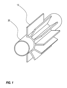
[049] FIG. 1 is a perspective illustration of a fragmented portion of a first
half of a bolt-on
heat fin partially surrounding an internal heating coil in accordance with one
or more
preferred embodiments.
[050] FIG. 2 is a cross-sectional schematic view of a heat fin bolted onto a
three inch
diameter carbon steel pipe.
[051] FIG. 3 includes a table which provides a summary of calculations for an
exemplary
scenario.
[052] FIG. 4 illustrates an exemplary single pass heat exchanger utilizing a
smaller pipe, a
heat fin, and a larger pipe.
DETAILED DESCRIPTION
[053] As a preliminary matter, it will readily be understood by one having
ordinary skill in
the relevant art ("Ordinary Artisan") that the present invention has broad
utility and
application. Furthermore, any embodiment discussed and identified as being
"preferred" is
considered to be part of a best mode contemplated for carrying out the present
invention.
Other embodiments also may be discussed for additional illustrative purposes
in providing a
full and enabling disclosure of the present invention. As should be
understood, any
embodiment may incorporate only one or a plurality of the above-disclosed
aspects of the
invention and may further incorporate only one or a plurality of the above-
disclosed features.
Moreover, many embodiments, such as adaptations, variations, modifications,
and equivalent
arrangements, will be implicitly disclosed by the embodiments described herein
and fall
within the scope of the present invention.
[054] Accordingly, while the present invention is described herein in detail
in relation to
one or more embodiments, it is to be understood that this disclosure is
illustrative and
exemplary of the present invention, and is made merely for the purposes of
providing a full
CA 02790423 2012-08-17
WO 2011/103410 PCT/US2011/025415
and enabling disclosure of the present invention. The detailed disclosure
herein of one or
more embodiments is not intended, nor is to be construed, to limit the scope
of patent
protection afforded the present invention, which scope is to be defined by the
claims and the
equivalents thereof. It is not intended that the scope of patent protection
afforded the
present invention be defined by reading into any claim a limitation found
herein that does
not explicitly appear in the claim itself.
[055] Thus, for example, any sequence(s) and/or temporal order of steps of
various
processes or methods that are described herein are illustrative and not
restrictive.
Accordingly, it should be understood that, although steps of various processes
or methods
may be shown and described as being in a sequence or temporal order, the steps
of any such
processes or methods are not limited to being carried out in any particular
sequence or order,
absent an indication otherwise. Indeed, the steps in such processes or methods
generally
may be carried out in various different sequences and orders while still
falling within the
scope of the present invention. Accordingly, it is intended that the scope of
patent protection
afforded the present invention is to be defined by the appended claims rather
than the
description set forth herein.
[056] Additionally, it is important to note that each term used herein refers
to that which
the Ordinary Artisan would understand such term to mean based on the
contextual use of
such term herein. To the extent that the meaning of a term used herein-as
understood by
the Ordinary Artisan based on the contextual use of such term-differs in any
way from any
particular dictionary definition of such term, it is intended that the meaning
of the term as
understood by the Ordinary Artisan should prevail.
[057] Regarding applicability of 35 U.S.C. 112,196, no claim element is
intended to be read
in accordance with this statutory provision unless the explicit phrase "means
for" or "step
for" is actually used in such claim element, whereupon this statutory
provision is intended to
apply in the interpretation of such claim element.
[058] Furthermore, it is important to note that, as used herein, "a" and "an"
each generally
denotes "at least one," but does not exclude a plurality unless the contextual
use dictates
otherwise. Thus, reference to "a picnic basket having an apple" describes "a
picnic basket
having at least one apple" as well as "a picnic basket having apples." In
contrast, reference to
"a picnic basket having a single apple" describes "a picnic basket having only
one apple."
[059] When used herein to join a list of items, "or" denotes "at least one of
the items," but
does not exclude a plurality of items of the list. Thus, reference to "a
picnic basket having
cheese or crackers" describes "a picnic basket having cheese without
crackers", "a picnic
CA 02790423 2012-08-17
WO 2011/103410 PCT/US2011/025415
11
basket having crackers without cheese", and "a picnic basket having both
cheese and
crackers." Finally, when used herein to join a list of items, "and" denotes
"all of the items of
the list." Thus, reference to "a picnic basket having cheese and crackers"
describes "a picnic
basket having cheese, wherein the picnic basket further has crackers," as well
as describes "a
picnic basket having crackers, wherein the picnic basket further has cheese."
[060] Referring now to the drawings, one or more preferred embodiments of the
present
invention are next described. The following description of one or more
preferred
embodiments is merely exemplary in nature and is in no way intended to limit
the invention,
its implementations, or uses.
[061] In accordance with one or more preferred embodiments, a heat fin made
from
aluminum or other high-conductivity material is configured to be bolted onto
an internal
heating coil. The heat fin is configured such that, when bolted onto an
internal heating coil
of a large scale container, it forms an external and removable heat enhancer
to increase heat
transfer from a heating medium flowing through the internal coil into product
contained in
the large scale container.
[062] FIG. 1 is a perspective illustration of a fragmented portion of a first
half 12 of a bolt-on
heat fin partially surrounding an internal heating coil 20 in accordance with
one or more
preferred embodiments. The portion is described as being fragmented because,
in at least
some preferred implementations, the heat fin will extend substantially the
entire length of an
internal heating coil it surrounds. In a preferred implementation, heat fins
are extruded in
approximately forty foot (40') length sections, although in at least some
preferred
implementations such heat fins may be cut to nine feet six inch (9'6") length
sections so as to
be shippable overnight by truck or air.
[063] The first half 12 is configured to be bolted to a second half 14 of the
heat fin such that
the heat fin is secured to an internal heating coil, as illustrated in FIG. 2,
which is a cross-
sectional schematic view of the heat fin bolted onto a three inch (3")
diameter (three and a
half inch (3.5") nominal) carbon steel pipe. It will be appreciated that
although only a single
bolt is illustrated in cross-section, bolts likely will be utilized to secure
the halves 12,14
together at both top and bottom portions of the halves 12,14 along the length
of the halves
12,14.
[064] The heat fin is configured to increase the heat transfer area of a coil
it is secured to. In
an exemplary scenario, such a heat fin can increase the total heat transfer of
normal pipe
internal coils by 600%. Table 1 of FIG. 3 provides a summary of calculations
for such
exemplary scenario.
CA 02790423 2012-08-17
WO 2011/103410 PCT/US2011/025415
12
[065] In this exemplary scenario, the total footage of internal coil required
to meet a
particular thermal duty of an application could be reduced by as much as six
(6) times, or
possibly even more in some cases. For example, if an internal coil was used to
heat asphalt
with a very low convection coefficient (1 BTU/hr ft" 2 F), six hundred feet
(600') of standard
internal coil might be equal to the heating capabilities of one hundred feet
(100') of internal
coil with a heat fin installed over the internal coil. This would make
internal coils much
more economical to install and maintain.
[066] Further, because the heat fin is bolted on, instead of hydro-blasting
the coils clean, the
bolted-on heat fin can be removed, cleaned and replaced, or removed and
replaced entirely.
[067] As noted above, in preferred implementations, heat fins (or heat fin
halves) are
extruded, such as, for example, from aluminum, and machined for bolting
purposes, although
in at least some implementations halves of heat fins may be secured together
in some other
manner, and may be configured for such securement in some other manner.
Preferably, heat
fins are anodized to extend their life under harsh conditions.
[068] In at least some alternative implementations, a heat fin is made from
carbon steel,
stainless steel, copper, a silicon-based compound, a graphite-based compound,
and/or one or
more high conductivity polymers or plastics.
[069] In preferred implementations, one or more heat fins are specifically
selected and/or
designed for a particular application by calculating heat lost through ambient
conditions and
overcoming such loss by adding enough heat into the process by way of heat fin
installation
onto internal heating coils. A heat fin may also be selected or designed to
meet a specific
heat-up requirement of the product.
[070] In at least some implementations, there exists a gap between a heat fin
bolted onto an
internal coil and the internal coil. In at least some such implementations,
this gap is
preferably bridged utilizing common heat transfer compounds. When used in thin
layers,
these compounds can provide rapid heat transfer from, for example, the carbon
steel surface
of an internal heating coil to an aluminum surface of a heat fin. These
compounds can have a
thermal conductivity of twenty five (25) to fifty (50) BTU/hr ft" 2 F when
used in very thin
layers.
[071] In preferred implementations, heat fins are applied to pipes or tubes,
including pre-
existing pipes or tubes, in a wide variety of contexts, including contexts
outside of an
internal heating coil context. For example, in a preferred implementation, a
heat fin is
secured to the outside of tubing to cool hydrogen inside of a purification
system.
CA 02790423 2012-08-17
WO 2011/103410 PCT/US2011/025415
13
[072] In another preferred implementation, one or more heat fins are utilized
in a heat
exchanger implementation. For example, in a simple heat exchanger
implementation, a heat
fin 110 is installed on the outside of a smaller pipe 120, such as a one inch
pipe, and a larger
pipe 130 is then secured (e.g. by welding) around the outside of the smaller
pipe and heat fin,
thereby creating a single pass heat exchanger, as illustrated in FIG. 4.
[073] Although described and illustrated herein primarily as including a
plurality of planar
portions extending from a curved portion, it will be appreciated that the
extending portions
may in fact be curved, or otherwise shaped, in at least some implementations.
[074] Based on the foregoing description, it will be readily understood by
those persons
skilled in the art that the present invention is susceptible of broad utility
and application.
Many embodiments and adaptations of the present invention other than those
specifically
described herein, as well as many variations, modifications, and equivalent
arrangements,
will be apparent from or reasonably suggested by the present invention and the
foregoing
descriptions thereof, without departing from the substance or scope of the
present invention.
Accordingly, while the present invention has been described herein in detail
in relation to
one or more preferred embodiments, it is to be understood that this disclosure
is only
illustrative and exemplary of the present invention and is made merely for the
purpose of
providing a full and enabling disclosure of the invention. The foregoing
disclosure is not
intended to be construed to limit the present invention or otherwise exclude
any such other
embodiments, adaptations, variations, modifications or equivalent
arrangements, the present
invention being limited only by the claims appended hereto and the equivalents
thereof.