Note: Descriptions are shown in the official language in which they were submitted.
CA 02791097 2012-08-23
WO 2011/133427
PCT/US2011/032708
MODULAR INTRAOCULAR LENS INJECTOR DEVICE
TECHNICAL FIELD
The present invention relates generally to an intraocular lens injector device
for surgically injecting an intraocular lens into an eye, and more
particularly to an
intraocular lens injector device that is modularized to enable cleaning of
internal
components after surgery.
BACKGROUND
The human eye functions to provide vision by transmitting light through a
clear outer portion called the cornea, and focusing the image by way of a
crystalline
lens onto a retina. The quality of the focused image depends on many factors
including the size and shape of the eye, and the transparency of the cornea
and the
lens. When age or disease causes the lens to become less transparent, vision
deteriorates because of the diminished light which can be transmitted to the
retina.
This deficiency in the lens of the eye is medically known as a cataract. An
accepted
treatment for this condition is surgical removal of the eye's natural lens and
replacement of the lens function by an artificial intraocular lens (IOL).
In the United States, the majority of cataractous lenses are removed by a
surgical technique called phacoemulsification. During this procedure, an
opening is
made in the anterior capsule and a thin phacoemulsification cutting tip is
inserted into
the diseased lens and vibrated ultrasonically. The vibrating cutting tip
liquefies or
emulsifies the lens so that the lens may be aspirated out of the eye. The
diseased
lens, once removed, is replaced by an artificial 10L.
An IOL injector device injects the artificial IOL into the eye through the
same
small incision used to remove the diseased lens. The IOL injector device
typically
includes a tubular housing with an injector rod disposed therein and a lens
cartridge
that contains the artificial 10L. With the tip of the lens cartridge inserted
into the
1
CA 02791097 2014-10-27
incision, the IOL injector device physically translates the injector rod
toward the lens
cartridge, thereby displacing the artificial 101 from the lens cartridge and
into the eye.
During surgery, substances often accumulate on the internal components of the
IOL injector device, including for example the injector rod. For instance,
viscoelastic
substances (e.g., Ophthalmic Viscoelastic Devices, OVD), which have both high
viscosity
and elasticity, are widely utilized in cataract surgery to create and reserve
space for, or to
coat, the artificial 10L. Accordingly, when the injector rod displaces the
artificial 101 from
the lens cartridge, viscoelastic substances unavoidably accumulate on the
surface of the
rod. If the injector rod is not re-processed (i.e., cleaned) to remove the
accumulated
viscoelastic substances, the substances can contaminate and introduce
complications to
subsequent patients undergoing cataract surgery with the same device.
SUMMARY
Teachings herein include a device for injecting an intraocular lens (IOL) into
the
lens capsule of an eye. The device is modularized to enable cleaning of
internal
components, such as an injector rod, after surgery.
Certain exemplary embodiments can provide a device for injecting an
intraocular
lens into an eye, the device comprising: a tubular housing comprising a first
module at a
front end of the housing and a second module posterior to the first module,
the first and
second modules collectively defining a passageway extending from the second
module,
through the first module, to the front end of the housing, wherein the first
module is
configured to accommodate a lens cartridge module at or near the front end of
the
2
CA 02791097 2014-10-27
housing that has an intraocular lens disposed therein, in alignment with said
passageway;
and an injector rod moveable along said passageway over an operating range
between a
retracted position and an extended position, wherein as the rod moves from the
retracted position to the extended position a front portion of the rod that is
substantially
surrounded by the first module in the retracted position moves into the
cartridge module
and displaces the intraocular lens therefrom; wherein the first module is
configured to
detach from the second module, to thereby expose the front portion of the rod
in the
retracted position for cleaning, wherein the second module is configured to,
when
detached from the first module, removably attach to a cleaning module
configured to
inject cleaning fluid onto said injector rod, and wherein the second module
includes a seal
member disposed within said passageway near a front end of the second module,
the
seal member and the rod configured to engage one another when the rod is in
the
retracted position, and to thereby prevent cleaning fluid injected onto the
rod by the
cleaning module from passing beyond said front end of the second module toward
a rear
end of the housing.
Certain exemplary embodiments can provide a device for injecting an
intraocular
lens into an eye, the device comprising: a tubular housing comprising a first
module at a
front end of the housing and a second module posterior to the first module,
the first and
second modules collectively defining a passageway extending from the second
module,
through the first module, to the front end of the housing, wherein the first
module is
configured to accommodate a lens cartridge module at or near the front end of
the
2a
CA 02791097 2014-10-27
housing that has an intraocular lens disposed therein, in alignment with said
passageway;
and an injector rod moveable along said passageway over an operating range
between a
retracted position and an extended position, wherein as the rod moves from the
retracted position to the extended position a front portion of the rod that is
surrounded
by the first module in the retracted position moves into the cartridge module
and
displaces the intraocular lens therefrom; wherein the first module is
configured to detach
from the second module, to thereby expose the front portion of the rod in the
retracted
position for cleaning, wherein the second module is configured to, when
detached from
the first module, removably attach to a cleaning module configured to inject
cleaning
fluid onto said injector rod, wherein the second module includes an injector
rod sleeve
that protrudes from the second module, toward the front end of the housing, in
cantilever fashion, that surrounds at least a portion of the rod
longitudinally disposed
therein, and that is configured to removably attach to the cleaning module,
and wherein
the injector rod sleeve has at least one fluid outlet port in a side wall
thereof that is
configured to dispel cleaning fluid injected into the injector rod sleeve and
onto the
injector rod by the cleaning module.
According to an exemplary embodiment, an 101 injection device includes a
tubular
housing that comprises a first module and a second module. The first module is
disposed
at a front end of the housing and the second module is disposed posterior to
the first
module, e.g., at a rear end of the housing. These modules collectively define
a
2b
CA 02791097 2014-10-27
passageway that extends from the second module, through the first module, to
the front
end of the housing. An injector rod is longitudinally disposed within and
moveable along
this passageway.
The first module is further configured to accommodate a lens cartridge
module at or near the front end of the housing. The lens cartridge module has
disposed
therein an 10L, in alignment with the passageway defined by the first and
second
modules. Aligned with the passageway, the IOL is displaced from the lens
2c
CA 02791097 2012-08-23
WO 2011/133427
PCT/US2011/032708
cartridge module by the injector rod as the rod moves along the passageway and
into
the lens cartridge module.
More particularly, the injector rod moves along the passageway over an
operating range between a retracted position and an extended position. A front
portion of the injector rod remains substantially surrounded by the first
module in the
retracted position. As the injector rod moves from the retracted position to
the
extended position, though, this front portion of the rod moves into the
cartridge
module and displaces the IOL therefrom.
When the IOL is injected into the eye in this way, substances used during
surgery (e.g., viscoelastic substances) accumulate on the internal components
of the
IOL injector device, especially the front portion of the injector rod. To
enable cleaning
of these internal components, the first module is configured to detach from
the
second module, to thereby expose the front portion of the injection rod in the
retracted position for cleaning. Once the front portion of the injector rod is
cleaned,
the first and second modules may be configured to then reattach for surgical
use.
In some circumstances of the device's surgical use, the internal components
of the device, can be adequately cleaned of accumulated substances as
described
above. In other circumstance, however, the substances may also accumulate on
those portions of the internal components not exposed by detaching the first
and
second modules as described. Accordingly, in other embodiments of the present
invention, the second module is configured to, when not attached to the first
module,
removably attach to a cleaning module (e.g., a syringe filled with a balanced
salt
solution and a tube for injecting that solution). The cleaning module is
configured to
inject cleaning fluid onto various internal components of the device, e.g.,
the injector
rod, including those portions not otherwise exposed when the injector rod is
in the
retracted position.
Of course, those skilled in the art will appreciate that the present invention
is
not limited to the above features, advantages, contexts or examples, and will
3
CA 02791097 2012-08-23
WO 2011/133427
PCT/US2011/032708
recognize additional features and advantages upon reading the following
detailed
description and upon viewing the accompanying drawings.
BRIEF DESCRIPTION OF THE DRAWINGS
Figure 1A is an isometric view of an exemplary IOL injection device, with a
lens cartridge module installed.
Figure 1B is a magnified view of the lens cartridge module and a first module
of the exemplary IOL injection device illustrated in Figure 1A.
Figure 1C is a cross-sectional view of Figure 1A, taken along line XX.
Figures 2A and 28 are cross-sectional views of an IOL injection device,
respectively illustrating an injector rod in a retracted position and in an
expanded
position.
Figures 3A and 38 are respectively isometric and cross-sectional views of an
IOL injection device modularized to enable cleaning of internal components
after
surgery, according to one embodiment of the present invention.
Figures 4A and 48 are respectively isometric and cross-sectional views of an
IOL injection device with various attachment features for removably attaching
the
modules of the device, according to one embodiment of the present invention.
Figures 5A-5E are various views of an IOL injection device configured to
removably attach to a cleaning module for cleaning, according to one
embodiment of
the present invention.
Figure 6 illustrates an injection rod that includes a removable plunger tip
according to some embodiments of the present invention.
DETAILED DESCRIPTION
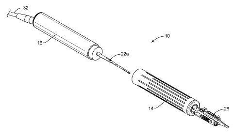
Figures 1A-1C illustrate a device 10 for injecting an artificial intraocular
lens
(IOL) into the anterior capsule of an eye. The IOL injection device 10
includes a
tubular housing 12 that comprises a first module 14 and a second module 16.
The
first module 14 is disposed at a front end 18 of the housing 12 and the second
4
CA 02791097 2012-08-23
WO 2011/133427
PCT/US2011/032708
module 16 is disposed posterior to the first module 14, e.g., at a rear end 20
of the
housing 12.
The modules 14, 16 are configured to house therein various internal
components of the IOL injection device 10. The modules 14, 16, for example,
house
an injector rod 22. More particularly, the modules 14, 16 collectively define
a
passageway 24 that extends from the second module 16, through the first module
14, to the front end 18 of the housing 12. The injector rod 22 is
longitudinally
disposed within and moveable along this passageway 24.
The first module 14 is further configured to accommodate a lens cartridge
module 26 at or near the front end 18 of the housing 12. In some embodiments,
for
instance, the first module 14 includes a lens cartridge module mount 28 that
is
press-fitted to the front end 18 of the housing 12. This lens cartridge module
mount
28 removably mounts the lens cartridge module 26 to the front end 18 of the
housing
12, e.g., via a unique cutout configured to hold the lens cartridge module 26.
The lens cartridge module 26 has disposed therein an intraocular lens (10L),
in alignment with the passageway 24 defined by the modules 14, 16. Aligned
with the
passageway 24, the IOL is displaced from the lens cartridge module 26 by the
injector rod 22 as the rod 22 moves along the passageway 24 and into the lens
cartridge module 26.
Specifically, as shown in Figures 2A-2B, the injector rod 22 moves along the
passageway 24 over an operating range between a retracted position (Figure 2A)
and an extended position (Figure 2B). In some embodiments, an electric drive
system 30 housed by the second module 30 and powered by a cable assembly 32
enables the injector rod 22 to move in this way. The electric drive system 30
may, for
example, include an electric motor and be configured to cause longitudinal
translation
of the injector rod 22 along the passageway 24 over the operating range
between the
retracted position and the extended position. The movement of the injector rod
22
along the passageway 24 may be limited to the operating range between the
5
CA 02791097 2012-08-23
WO 2011/133427
PCT/US2011/032708
retracted position and the extended position by one or more mechanical stops
34, by
electrical control signals, or some combination of both.
Irrespective of the means by which the rod 22 is moved, a front portion 22a of
the rod 22 remains substantially surrounded by the first module 14 in the
retracted
position. As the rod 22 moves from the retracted position to the extended
position,
the front portion 22a of the rod 22 moves into the lens cartridge module 26
and
displaces the IOL therefrom and into the eye.
When the IOL is injected into the eye in this way, the internal components of
the IOL injector device 10, especially the front portion 22a of the injector
rod 22, may
accumulate on them substances used during surgery (e.g., viscoelastic
substances).
If the injector rod 22 is not cleaned to remove the accumulated substances,
the
substances can contaminate and introduce complications to subsequent patients
undergoing cataract surgery with the same device 10.
Accordingly, the device 10 is modularized as shown in Figures 3A-3B to
enable cleaning of internal components like the injector rod 22 after surgery.
As
pictured, the first module 14 is configured to detach from the second module
16, to
thereby expose the front portion 22a of the injector rod 22 in the retracted
position for
cleaning. Cleaning may simply entail wiping off the substances accumulated on
the
front portion 22a of the injector rod 22, or more thoroughly entail flushing,
soaking,
and ultrasonically sterilizing the front portion 22 of the injector rod 22.
Once the front
portion 22a of the injector rod 22 is cleaned, the first module 14 and the
second
module 16 may be configured to then reattach for surgical use.
In some embodiments, for example, the first module 14 includes a first
attachment feature and the second module 16 includes a second attachment
feature.
These attachment features are configured to attach to one another, for
surgical use,
and to detach from one another, for cleaning. In one embodiment, the first and
second attachment features are respective portions of a snap-fit mechanism
that
enables the first module 14 to snap onto the second module 16, and to likewise
snap
6
CA 02791097 2012-08-23
WO 2011/133427
PCT/US2011/032708
loose from the second module 16. In another embodiment, the first attachment
feature comprises mechanical threads disposed on an interior surface of the
first
module 14, while the second attachment feature comprises mechanical threads
disposed on an exterior surface of the second module 16. These mechanical
threads
are configured to engage with one another, to permit attachment and detachment
of
the first and second modules 14, 16. Yet another embodiment includes some
combination of these snap-fit mechanisms and mechanical threads.
Consider, for example, the embodiments illustrated in Figures 4A-4B. In
Figures 4A-4B, the second module 16 includes an injector rod sleeve 36
concentric
therewith. The injector rod sleeve 36 protrudes from the second module 16,
toward
the front end 18 of the housing 12, in cantilever fashion, and surrounds at
least a
portion of the rod 22 longitudinally disposed therein. The injector rod sleeve
36
includes mechanical threads 38 disposed on an exterior surface thereof. These
mechanical threads 38 are configured to engage mechanical threads 40 disposed
on
an interior surface of the first module 14. Additionally, the first and second
modules
14, 16 include respective portions of one or more snap-fit mechanisms 42 that,
when
engaged, snap or secure the modules 14, 16 together. Accordingly, the modules
14,
16 are configured to attach together in these embodiments by the first module
14
overlapping and screwing onto the injector rod sleeve 36, via the mechanical
threads
38, 40, until the snap-fit mechanism(s) 42 engage. When the modules 14, 16 are
attached in this way, the first module 14 surrounds the injector rod sleeve 36
and the
front portion 22a of the injector rod 22. The modules 14, 16 are configured to
detach
from one another in a reverse manner, to once again expose the injector rod
sleeve
36 and the front portion 22a of the injector rod 22 for cleaning.
In most circumstances of the device's surgical use, the internal components
of the device 10, e.g., the injector rod 22, can be adequately cleaned of
accumulated
substances as described above. Indeed, in most circumstances, the substances
accumulate only on the front-most portions of the internal components, such as
the
7
CA 02791097 2012-08-23
WO 2011/133427
PCT/US2011/032708
front portion 22a of the injector rod 22, and thus exposing only these
portions for
cleaning is often adequate.
In other circumstances, however, the substances may also accumulate on
those portions of the internal components not exposed by the embodiments
above. In
the embodiments illustrated in Figures 4A-4B, for instance, the substances may
accumulate on those portions of the injector rod 22 that are surrounded by the
injector rod sleeve 36. Simply detaching the first module 14 from the second
module
16 as described above therefore does not sufficiently expose these portions
when
the injector rod 22 is in the retracted position for cleaning.
Accordingly, Figures 5A-5E illustrate embodiments directed to cleaning
internal components of the device 10 not sufficiently exposed by detaching the
first
module 14 from the second module 16. In these embodiments, the second module
16 is configured to, when detached from the first module 14, removably attach
to a
cleaning module 44. The cleaning module 44 is configured to inject cleaning
fluid
onto various internal components of the device 10, e.g., the injector rod 22,
including
those portions not exposed when the injector rod 22 is in the retracted
position and
when the second module 16 is detached from the first module 14.
More particularly, the first and second modules 14, 16 in these embodiments
may be configured to attach and detach in much the same way as described
above;
that is, via mechanical threads 38 disposed on an external surface of an
injector rod
sleeve 36 that engage with mechanical threads 40 disposed on an internal
surface of
the first module 14, and/or via respective portions of one or more snap-fit
mechanisms 42. Additionally, though, the injector rod sleeve 36 may be
configured to
removably attach to the cleaning module 44 when not attached to the first
module 14.
For example, the injector rod sleeve 36 may further include a cleaning module
connector 36a that protrudes from the second module 16 toward the front end 18
of
the housing 12 in cantilever fashion. This cleaning module connector 36a is
sized
and configured to removably attach to the cleaning module 44.
8
CA 02791097 2012-08-23
WO 2011/133427
PCT/US2011/032708
As pictured, the cleaning module 44 includes a syringe 46 filled with a
cleaning fluid (e.g., a sterile balanced salt solution) and a tube 48. One end
48a of
the tube 48 is configured to attach to the syringe 46. The other end 48b of
the tube
48 is configured to pass over the front portion 22a of the injector rod 22 in
the
retracted position and to attach to the second module 16, e.g., via the
cleaning
module connector 36a of the injector rod sleeve 36, which is sized and
configured for
such attachment. With the syringe 46 attached to the second module 16 in this
way,
cleaning fluid can be injected by the syringe into the injector rod sleeve 36
and onto
those internal components of the device 10 not exposed by the detachment of
the
first module 14.
In some embodiments, the injector rod sleeve 36 has at least one fluid outlet
port 36b in a side wall thereof. The fluid outlet port 36b is configured to
dispel
cleaning fluid injected into the injector rod sleeve 36 and onto the injector
rod 22 by
the cleaning module 44. As pictured, for example, cleaning fluid flows from
the
syringe 46, through the tube 48, into the injector rod sleeve 36, onto
otherwise
unexposed portions of the injector rod 22 and other unexposed internal
components
of the device 10, and out of the fluid outlet port 36b.
To prevent cleaning fluid injected by the cleaning module 44 from flowing into
undesired portions of the device 10, e.g., near the electric drive system 30
at the rear
end 20 of the housing 12, various embodiments such as the one illustrated in
Figure
5E include a seal member 50. The seal member 50 may for instance comprise a
compression seal made up of an elastomer jacket and a metal channel ring. In
the
embodiment of Figure 5E, the seal member 50 is disposed within the passageway
24
near a front end 16a of the second module 16. So disposed, the seal member 50
and
the injector rod 22 are configured to engage one another when the rod 22 is in
the
retracted position. Engaged in this way, the seal member 50 prevents cleaning
fluid
injected onto the rod 22 from passing beyond the front end 16a of the second
module
16 toward the rear end 20 of the housing 12. The seal member 50 thus also, in
9
CA 02791097 2012-08-23
WO 2011/133427
PCT/US2011/032708
certain embodiments, facilitates the dispelling of the cleaning fluid out of a
fluid outlet
port 36b.
Those skilled in the art will appreciate that, although the injector rod 22
was
described above for illustrative purposes as comprising a single integral
part, the
injector rod 22 may comprises two or more parts as shown in Figure 6. As shown
in
Figure 6, the front portion 22a of the injector rod 22 comprises a plunger tip
that is
configured to removably attach to a remaining portion 22b of the injector rod
22. In
some embodiments, the plunger tip may comprise a removable plastic sleeve that
snap-fits onto the remaining portion 22b of the rod 22, and may be disposable
after
use. Furthermore, the end of the plastic sleeve that engages the IOL is more
compliant than a bare metallic plunger tip would be, and has a smooth surface
finish,
thus avoiding damage to the IOL as it is pushed through the lens cartridge
module 26
and into the eye. The use of a disposable plastic sleeve may also ease
cleaning of
the IOL injection device 10 between uses, as fewer portions of the injector
rod 22
need by cleaned as described above.
Thus, the preceding description of various embodiments of an intraocular lens
injection device was given for purposes of illustration and example. Those
skilled in
the art will appreciate that the present invention may be carried out in other
ways
than those specifically set forth herein without departing from essential
characteristics of the invention. The present embodiments are thus to be
considered
in all respects as illustrative and not restrictive, and all changes coming
within the
meaning and equivalency range of the appended claims are intended to be
embraced therein.