Note: Descriptions are shown in the official language in which they were submitted.
CA 02791328 2012-09-27
HYDRAULICALLY DRIVEN TOOL
[0001] This application claims the domestic benefit of United States
provisional application
Serial No. 611541,674, filed on September 30, 2011, which disclosure is herein
incorporated by
reference in its entirety.
BACKGROUND OF THE INVENTION
[00021 Existing hydraulic tools, such as hydraulic wrenches, generate heat as
result of the use
of high temperature hydraulic fluid passing through the tool, The user grips a
grip which
surrounds a metal valve body through which the high temperature hydraulic
fluid passes. It is
desirable to prevent the transfer of this heat to the user's hand. The prior
art insulates the metal
valve body with a PVC-based dip, which tends to be inadequate to prevent the
passage of heat
generated by the high temperature hydraulic fluid. In addition, the PVC-based
dip is not very
durable and is not easy to replace if the tool becomes damaged.
[0003] Prior art tools have controlled flow in a circuit, and thus output
motor torque in the
circuit. A control for setting the torque to two discrete settings has been
used in the prior art.
This presents a disadvantage in that only two settings are provided. Other
prior art tools have
used a pressure compensated flow control mechanism with an infinite adjustment
setting.
Pressure compensated flow control mechanisms are costly to manufacture.
[0004] A hydraulically driven tool is provided herein which provides
improvements to
existing tools and which overcomes the disadvantages presented by the prior
art. Other features
and advantages will become apparent upon a reading of the attached
specification, in
combination with a study of the drawings.
SUMMARY OF THE INVENTION
[0005] A handle for a hydraulically driven tool, such as a wrench or a drill,
which reduces the
amount of heat transmitted to the user of the tool is disclosed. The tool has
a body formed of a
heat transmissive material which has at least one channel through which a high
temperature fluid
I
CA 02791328 2012-09-27
flows. Heat is generated as a result of the fluid. The body includes a
plurality of fastener
receiving passageways therethrough; each passageway has a countersink provided
at each end
thereof. The handle is non-conductive and generally surrounds the body. The
interior surface of
the handle has a plurality of spaced apart standoffs extending therefrom. The
standoffs contact
the body and an air gap is formed between the interior surface and the body at
locations where
standoffs are not provided. This provides for a minimal amount of surface
contact between the
metal valve body 64 and the nonconductive grip housing 66a, 66b which reduces
the amount of
conduction from the heat transmissive body to the non-conductive handle, and
thus to the user's
hand which surrounds this area. In addition, the air gap allows air flow
between the body and the
handle for convection cooling of the body. The interior surface has a
plurality of fastener
receiving extensions, each having an aperture therethrough, which align with
the respective
passageways. The fastener receiving extensions seat within the countersinks
and the fastener
receiving extensions are smaller than the countersinks. As a result, the
fastener receiving
extensions do not contact the body to aid in minimizing the amount of heat
transmitted to the
handle,
[0006] A bypass assembly is provided for varying the hydraulic motor
revolutions per minute
(rpm) of a hydraulically driven tool, such as a wrench or a drill. This
controls the torque of a
driven mechanical mechanism, such as used on an impact wrench. The tool
includes a body
having a supply channel capable of being connected a source of fluid, a bypass
spool channel in
fluid communication with the supply channel, and a return channel in fluid
communication with
the bypass spool channel via a port and in fluid communication with the
source. A bypass spool
seats in the bypass spool channel. The bypass spool can be rotated to three
discrete positions
within the bypass spool channel to provide three different settings of
revolutions per minute
(rpm) of the gear motor.
[00071 A relief valve assembly limits the maximum torque of a gear motor of a
hydraulically
driven tool. The relief valve assembly dumps flow to a return channel to
return hydraulic fluid to
the supply when the relief valve assembly is activated at a set pressure
setting. The relief valve
assembly includes a directional valve spool seated in a spool receiving
channel and varies its
2
CA 02791328 2012-09-27
pressure setting depending upon spool position. This is useful to vary the
pressure settings of a
hydraulic motor in different directions. The spool has a bore having a first
portion and a second
smaller portion such that a seat is defined. First passageways extend from the
first portion, and
second passageways extend from the second portion. A coiled spring is mounted
in the bore and
has a pin seated therewithin. The spool can be moved within the spool
receiving channel to
cause the second passageways to align with each of the ports thereby changing
the direction of
rotation of the motor depending upon which of the ports is aligned with the
second passageways.
In operation, fluid flows from the supply to the spool receiving channel,
through said one of the
second passageways, into the second portion of the bore, through another one
of the second
passageways, and through the port which is aligned with the second
passageways. When the
motor encounters resistance, pressure from the fluid builds in the second
portion and causes the
pin to unseat from the seat such that fluid flows past the pin and into the
first portion of said
bore, through the first passageways and to the return channel. Through
differential pressure drop
differences within the fluid paths, the pressure setting of the relief valve
assembly is changed by
changing the position of the directional valve spool in which the relief valve
assembly is placed.
This is advantageous if a differential motor torque setting is needed in
forward than in reverse.
BRIEF DESCRIPTION OF THE DRAWINGS
[0008] The organization and manner of the structure and operation of the
invention, together
with further objects and advantages thereof, may best be understood by
reference to the following
description, taken in connection with the accompanying drawings, wherein like
reference
numerals identify like elements in which:
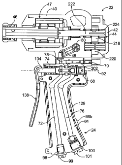
[0009] FIG. I is a side elevational view of a tool which incorporates the
features of the
present invention;
[0010] FIG. 2 is a cross-sectional view of the tool;
[0011] FIG, 3 is a partial cross-sectional view of the tool;
[0012] FIG. 4 is an alternate cross-sectional view of the tool;
[0013] FIG. 5 is a perspective view of a grip assembly which forms a portion
of the tool;
3
CA 02791328 2012-09-27
[00141 FIG. 6 is an exploded perspective view of the grip assembly;
[0015] FIG. 7 is a perspective view of a portion of a handle of the grip
assembly; {
[00161 FIG. 8 is a side elevational view of the portion of the handle;
[0017] FIG. 9 is a cross-sectional, perspective view of an inner body of the
grip assembly;
[00181 FIG. 10 is a side elevational view of the portion of the inner body;
[0019] FIG. 11 is a side elevational view of a trigger spool assembly which
forms a portion of
the tool;
[0020] FIG. 12 is a perspective view of a trigger spool which forms part of
the trigger spool
assembly;
[0021] FIG. 13 is a perspective view of a bypass spool assembly which forms a
portion of the
tool;
[0022] FIGS. 14 and 15 are cross-sectional views of the bypass spool assembly;
[0023] FIG. 16 is a cross-sectional view of the tool;
[0024] FIG. 17 is a perspective view of a work unit assembly which forms a
portion of the
tool;
[0025] FIGS. 18-21 are various cross-sectional views of the tool;
[0026] FIG. 22 is an exploded perspective view of a reversing spool assembly
which forms a
portion of the tool;
[0027] FIG. 23 is a side elevational view of a reversing spool which forms a
portion of the
reversing spool assembly; and
[0028] FIG. 24 is a cross-sectional view of the reversing spool assembly.
4
CA 02791328 2012-09-27
DETAILED DESCRIPTION OF THE ILLUSTRATED EMBODIMENT
[0029] While the invention may be susceptible to embodiment in different
forms, there is
shown in the drawings, and herein will be described in detail, a specific
embodiment with the
understanding that the present disclosure is to be considered an
exemplification of the principles
of the invention, and is not intended to limit the invention to that as
illustrated and described
herein. Therefore, unless otherwise noted, features disclosed herein may be
combined together to
form additional combinations that were not otherwise shown for purposes of
brevity.
[0030] A fluid-operated tool 20, such as a hydraulic wrench or drill, includes
a fluid control
system which provides for variable limitation of power output. The fluid
control system provides
multiple flow paths to provide for, among other things, selectable diversion
of a portion of flow
to a work unit assembly 22 of the tool 20, and reversing the direction of the
work unit assembly
22. The tool 20 may be used by professional linemen who work outdoors under a
variety of
conditions, including blistering heat and intense cold.
[0031] The tool 20 is a two piece design formed of the work unit assembly 22
and a grip
assembly 24. The work unit assembly 22 has a series of ports 26, 28, 30, see
FIG. 17, which
align with ports 32, 34, 36, see FIG. 5, in the grip assembly 24. 0-rings 38
seal the connections
between the ports 26/32, 28134, 30/36.
[0032] The work unit assembly 22 includes an impact mechanism housing 40, a
motor
housing 42 attached to the impact mechanism housing 40, a gear motor 44
mounted in the motor
housing 42, and a chuck 46 attached to the gear motor 44 by a rotary impact
mechanism 47. A
bit or other tool (not shown) is mounted to the chuck 46. A plurality of
channels 48, 50, 52, 54,
56, 58, see FIGS. 19-21, are provided in the impact mechanism housing 40 to
supply the gear
motor 44 with hydraulic fluid as discussed in further detail herein. A motor
reversing spool
assembly 62, FIGS. 21-24, is mounted within channel 50 as discussed herein.
[0033] As shown in FIGS. 1-4, the grip assembly 24 includes an inner valve
body 64, an outer
grip housing 66a, 66b, generally surrounding the inner valve body 64, a
trigger spool assembly
68 and a bypass spool assembly 70. A plurality of channels 72, 74, 76, 78,
80a/80b, 82, 84 are
provided in the inner valve body 64 as discussed in further detail herein. The
grip assembly 24 is
CA 02791328 2012-09-27
attached to a supply (not shown) which provides hydraulic fluid to the tool
20.
[0034] The inner valve body 64 is formed of heat transmissive material, such
as metal,
preferably sand cast aluminum. The outer grip housing 66a, 66b, which the user
grips with
his/her hand, is formed of a non-conductive material, preferably nylon, and
includes first and
second halves 66a, 66b.
[0035] As shown in FIG. 6, the inner valve body 64 is formed of an elongated
portion 86
which has a trigger spool platform 88 formed at the top end thereof, and a
bypass valve platform
90 extending from the upper end of the trigger spool platform 88. An axis 92
is defined through
the centerline of the trigger spool platform 88 and extends from a front end
94 to a rear end 96 of
the trigger spool platform 88.
[0036] As shown in FIG. 2, a pressure/pump port 98 and a return/tank port 100
are provided
in the bottom end of the inner valve body 64. An inlet channel 72 extends from
the
pressure/pump port 98 to a trigger spool channel 74 in which the trigger spool
assembly 68 is
mounted to provide for the flow of hydraulic fluid from the supply to the
trigger spool channel
74. An outlet channel 76 extends from the trigger spool channel 74 to the
return/tank port 100 to
provide for the flow of hydraulic fluid from the trigger spool channel 74 to
the supply. The tool
20 is typically used in utility applications and is connected to a hydraulic
power unit or auxiliary
circuit in a boom truck or tractor via the ports 98, 100. When the ports 98,
100 are not connected
to the supply, suitable caps 99, 101 cover the ports 98, 100.
[0037] The trigger spool channel 74 extends along the axis 92 through the
trigger spool
platform 88. The trigger spool channel 74 is generally cylindrical and extends
from the front end
94 of the trigger spool platform 88 to the rear end 96 of the trigger spool
platform 88. A C-clip
receiving groove 102, FIG. 9, is provided in the wall forming the trigger
spool channel 74
proximate to the front end 94. An enlarged O-ring receiving groove 104 is
provided in the wall
forming the trigger spool channel 74 proximate to the rear end 94. The wall of
the trigger spool
channel 74 has an enlarged fluid chamber 106 provided at the junction between
the trigger spool
channel 74 and the inlet channel 72; an enlarged fluid chamber 108 provided at
the junction
between the trigger spool channel 74 and the outlet channel 76; and an
enlarged fluid chamber
6
CA 02791328 2012-09-27
110 provided between and spaced from the enlarged fluid chamber 106 and the
enlarged fluid
chamber 108.
[0038] A bypass spool channel 78 extends parallel to the axis 92 through the
bypass spool
platform 90. The bypass spool channel 78 is generally cylindrical and extends
from a rear end
112 of the bypass spool platform 90 forwardly a predetermined distance.
[0039] A transfer supply channel 80a/80b has a first portion 80a which
connects the enlarged
fluid chamber l 10 of the trigger spool channel 74 to the bypass spool channel
78 and a second
portion 80b which connects the bypass spool channel 78 to the outlet port 32
in the upper end of
the grip assembly 24. The outlet port 32 supplies fluid to the work unit
assembly 22 of the tool
20.
[0040] A return transfer channel 82 connects port 34 to the enlarged fluid
chamber 108 of the
trigger spool channel 74 (see FIG. 4); return transfer channel 84 connects
port 36 to the enlarged
fluid chamber 108 of the trigger spool channel 74 (see FIG. 4). Ports 34, 36
receive fluid from
the work unit assembly 22 as described herein. The bypass spool channel 78 is
connected to the
return transfer channel 82 at port 116.
[0041] As shown in FIG. 6, the inner valve body 64 has a pair of spaced apart
fastener
receiving passageways 118 extending through the trigger spool platform 88, and
another fastener
receiving passageway 118 extending through the elongated portion 86 proximate
to the bottom
thereof. A countersink 120 is provided in each side of the inner valve body 64
at each end of the
respective fastener receiving passageway 118.
[0042] The first and second halves 66a, 66b of the grip housing are the mirror
image of each
other. The halves 66a, 66b are designed to minimize the amount of heat
transfer to the user of
the tool 20 which results from the use of high temperature hydraulic fluid
passing through the
tool 20. Halve 66b is shown in FIGS, 7 and 8. Each half 66a, 66b has a wall
120 which mirrors
the shape of half of the inner valve body 64. Each wall 120 has an interior
surface 122 which
faces the inner valve body 64 and an exterior surface 124 which the user
grasps with his/her
hand. First, second and third fastener receiving extensions 126 extend from
the interior surfaces
122 and each has an aperture 128 provided therethrough. A plurality of spaced
apart standoffs
7
CA 02791328 2012-09-27
it
128 extend from the interior surfaces 122. The standoffs 128 are preferably
cross-shaped,
however, other shapes are within the scope of the present invention. A
plurality of spaced apart
ribs 130 extend from the interior surfaces 122 at an upper end thereof. Each
half 66a, 66b can be
formed by injection molding.
[0043] When the halves 66a, 66b are assembled with the inner valve body 64,
the halves 66a,
66b substantially cover the sides of the inner valve body 64. The user grasps
the area of the outer
grip housing 66a, 66b which surrounds the elongated portion 86 of the inner
valve body 64. The
respective apertures 128 and passageways 118 align with each other such that
the fastener
receiving extensions 126 seat within the countersinks 120, however, the
fastener receiving
extensions 126 are smaller than the countersinks 120 such that the fastener
receiving extensions
126 do not contact the metal inner valve body 64. The halves 66a, 66b are
assembled with the
inner valve body 64 by a plurality of fasteners 132, such as bolts, which pass
through the
apertures 128 and passageways 118. The ribs 130 and the standoffs 128 contact
the inner valve
body 64, and an air gap 129 is formed between the walls 120 and the inner
valve body 64 at the
points between the ribs 130 and the standoffs 129. Preferably, the air gap 129
provides a spacing
of 0.10" between the walls 120 and the inner valve body 64. Therefore, a
minimal amount of
surface contact is provided between the metal valve body 64 and the non-
conductive grip housing
66a, 66b which reduces the amount of conduction from the metal valve body 64
to the non-
conductive grip housing 66a, 66b, and thus to the user's hand which surrounds
this area. In
addition, the air gap 129 allows air flow between the inner valve body 64 and
the grip housing
66a, 66b for convection cooling of the inner metal valve body 64.
[0044] A soft grip material 67 preferably surrounds the halves 66a, 66b of the
grip housing.
The soft grip material 67 helps to insulate the user from the heat generated
by the hydraulic fluid.
[00451 As shown in FIGS. 3, 11 and 12, the trigger spool assembly 68 includes
a trigger spool
134 mounted in the trigger spool channel 74, a spring assembly 136 for sealing
the trigger spool
134 to the wall forming the trigger spool channel 74 and for biasing the
trigger spool 134, a
trigger 138 attached by C-clips to the trigger spool 68 which extends from the
trigger spool
channel 74, and a system adjusting spool assembly 140 provided in a rear end
of the trigger spool
8
CA 02791328 2012-09-27
134. The trigger 138 can be depressed by the user to move the trigger spool
134 backward and
forward along the axis 92 in the trigger spool channel 74.
[00461 The trigger spool 134 is generally cylindrical. A first cylindrical
section 146 of the
trigger spool 134 extends rearwardly a predetermined distance from the front
end 142. An
aperture 148 is provided through the first section 146 proximate to the front
end 142 for
connection of the trigger spool 134 to the trigger 138. The first section 146
has a predetermined
outer diameter which is smaller than the inner diameter of the trigger spool
channel 74. A flange
150 extends from the first section 146 at a position spaced from the front end
142. The flange
150 has an outer diameter which is approximately the same as the inner
diameter of the trigger
spool channel 74. A second section 152 extends from the rear end of the first
section 146. The
second section 152 has an outer diameter which is approximately the same as
the inner diameter
of the trigger spool channel 74. A third section 154 extends from the rear end
of the second
section 152. The third section 154 has an outer diameter which is
approximately the same as the
first section 146 and thus is smaller than the inner diameter of the trigger
spool channel 74. A
fourth section 156 extends from the rear end of the third section 154. The
fourth section 156 has
an outer diameter which is less than the diameter of the second section 152,
but greater than the
outer diameter of the third section 154. A fifth section 158 extends from the
rear end of the
fourth section 156. The fifth section 158 has an outer diameter which is
approximately the same
as the inner diameter of the trigger spool channel 74, and is larger than the
diameter of the fourth
section 156.
[0047] A central bore 160, FIG. 3, extends from the rear end of the trigger
spool 134 and
extends axially forwardly through the fifth, fourth, third and second sections
158, 156, 154, 152.
The central bore 160 terminates in the second section 152. The central bore
160 has a forward
portion 162, an intermediate portion 164 and a rearward portion 166. The
forward portion 162
extends through the second and third sections 152, 154 and is smaller in
dimension than the
intermediate portion 164 which extends through the fourth section 156 and part
of the fifth
section 158. As a result, a seat 168 is formed between the forward and
intermediate portions
162, 164 of the central bore 160. A first set of four spaced apart passageways
170 extend radially
9
CA 02791328 2012-09-27
outwardly from the forward portion 162 of the central bore 160 through the
second section 152 of
the trigger spool 134. A second set of four spaced apart passageways 172
extend radially
outwardly from the intermediate section 164 of the central bore 160 through
the fourth section
156 of the trigger spool 134. The rearward portion 166 of the central bore 160
is threaded and
extends through the fifth section 158 of the trigger spool 134. The rearward
portion 166 of the
central bore 160 is larger in dimension than the intermediate portion 164 of
the central bore 160,
and as a result, a seat 173 is formed between the intermediate and rearward
portions 164, 166.
The rear end 144 of the central bore 160 is open and thus is accessible to the
user.
[0048] The trigger spool 134 is mounted in the trigger spool channel 74 such
that the front
end of the trigger spool 134 extends outwardly from the front end of the too]
20 and connects to
the trigger 138. The spring assembly 136 seats between the flange 150 and the
front end 94 of
the trigger spool platform 88. The spring assembly 136 includes a C-clip 174
which seats within
the corresponding C-clip receiving groove 102 in the trigger spool channel 74,
a washer 176
which seats against the C-clip 174, a spring 178 seated between the washer 176
and the flange
150, and a rubber O-ring 180 which seats around the first section 146 between
the flange 150 and
the second section 152. The trigger spool 74 can move axially along the
trigger spool channel 74
by compressing the spring 178.
[0049] As shown in FIG. 3, the system adjusting spool assembly 140 is mounted
within the
trigger spool 134. The system adjusting spool assembly 140 includes an
adjusting spool 182
which seats within the intermediate and rearward sections 164, 166 of the
central bore 160 and is
sealed thereto by a rubber O-ring 183. A C-clip 184 seats within a sloped
recess 186 provided in
the wall forming the rearward section 166. A user can adjust the position of
the adjusting spool
182 by screwing the adjusting spool 182 forward to move the adjusting spool
182 along the
trigger spool channel 74 until ball 1 94 seats on seat 168, or can be screwed
in reverse until the'
adjusting spool 182 backs onto C-clip 184. The C-clip 184 holds the adjusting
spool 182 in
position and prevents the removal of the adjusting spool 182 from the central
bore 160. A rubber
0-ring 190 and back up ring 192 seat around the fifth section 158 and seat
within the enlarged 0-
ring receiving groove 104. The system adjusting spool assembly 140 includes a
ball 194 which
CA 02791328 2012-09-27
seats within the fourth and fifth sections 156, 158 of the central bore 160.
The ball 194 abuts
against the forward end of the adjusting spool 182. The ball 194 is moved by
the user adjusting
the position of the adjusting spool 182. The ball 194 can be moved to seat
against the seat 168,
thus closing the fluid communication between the forward portion 162 and the
intermediate
portion 164 (and thus the radial passageways 172), or can be moved away from
the seat 168, thus
opening the fluid communication between the forward portion 162 and the
intermediate portion
164 (and thus the radial passageways 172).
[0050] When the trigger 138 is not depressed, the first set of passageways 170
are in
alignment with the inlet channel 72 to receive hydraulic fluid. If the tool 20
is to be operated in
an open-center configuration, the system adjusting spool assembly 140 is
adjusted to move the
ball 194 away from the seat 168. As a result, the hydraulic fluid can
continuously flow from the
supply, through the inlet channel 72, through the first set of passageways
170, through the
forward portion 162 of the central bore 160, past the seat 168, into the
intermediate section 163
of the central bore 160, through the second set of passageways 172 and into
the return channel
76. If the tool 20 is to be operated in a closed-center configuration, the
system adjusting spool
assembly 140 is adjusted to move the ball 194 against the seat 168. As a
result, the hydraulic
fluid cannot flow into the intermediate section 163 of the central bore 160
and through the
second set of passageways 172.
[0051] The bypass spool channel 78 is generally cylindrical and extends from a
front end 196
of the bypass spool platform 90 to a rear end 198 of the bypass spool platform
90. The front end
of the bypass spool channel 78 is closed by an adjusting spool 200 as shown in
FIG. 16. The rear
end of the bypass spool channel 78 is open.
[0052] The bypass spool assembly 70, see FIGS. 13 and 14, includes a bypass
spool 202
which is seated in the bypass spool channel 78, and a knob 204. The bypass
spool 202 is
generally cylindrical and has first and second opposite ends 206, 208. The
second end 208 of the
bypass spool 202 extends outwardly from the bypass spool channel 78 and the
knob 204 is
mounted thereon by suitable means. A central bore 210 extends rearwardly from
the first end
206 of the bypass spool 202 a predetermined distance. The open end of the
central bore 210 is in
11
CA 02791328 2012-09-27
fluid communication with the transfer channel 80a, 80b. First and second
passageways 212, 214,
FIGS. 14 and 15, extend radially outwardly from the central bore 210 proximate
to, but spaced
from, the first end 206 thereof. The passageways 212, 214 are perpendicular to
each other. The
first passageway 212 has a smaller diameter than the second passageway 214.
The bypass spool
202 is sealed to the bypass spool channel 78 by a pair of spaced apart O-rings
216, The bypass
spool 202 can be rotated to be in one of three discrete positions within the
bypass spool channel
78 by a user grasping the knob 204 and rotating it. In a first position,
neither radial passageway
212, 214 aligns with the port 116 (which connects the bypass spool channel 78
to the return
transfer channel 82) and hydraulic fluid does not flow through the central
bore 210 to either
radial passageway 212, 214. This configuration provides for high revolutions
per minute (rpm)
of the gear motor 44 as the all of the hydraulic fluid flows to the work unit
assembly 22. In the
second position, radial passageway 212 aligns with the port 116, and hydraulic
fluid flows
through the central bore 210, to the first, smaller radial passageway 212,
through port 116,
through the return channel 82, through enlarged chamber 108, and into return
channel 76. This
configuration provides for medium revolutions per minute (rpm) of the gear
motor 44 as most of
the hydraulic fluid flows to the work unit assembly 22, but some of the
hydraulic fluid is diverted
to the return channel 76. In the third position, radial passageway 214 aligns
with the port 116,
and hydraulic fluid flows through the central bore 210 to the second, larger
radial passageway
214, through port 116, through the return channel 82, through enlarged chamber
108, and into
return channel 76. This configuration provides for low revolutions per minute
(rpm) of the gear
motor 44 as most of the hydraulic fluid is diverted to the return channel 76,
and some of the
hydraulic fluid flows to the work unit assembly 22. The work assembly unit 22,
is connected to
the rotary impact mechanism 47. Therefore, the hydraulic motor work assembly
revolutions per
minute (rpm) will govern the output torque of the tool 20.
[0053] As a result of this structure, the bypass spool assembly 70 is formed
from a movable
bypass spool 202 which form a valveless conduit. The bypass spool 202 is
adapted for diverting
a portion of the inlet flow from entering the work unit 22 directly to a
return flow from the work
unit 22. The bypass spool 202 is movable about an axis generally orthogonal to
an axis of
12
CA 02791328 2012-09-27
movement of a motor reversing spool 230 discussed herein.
[0054] As shown in FIGS. 2 and 18, the gear motor 44 includes a pair of gears
218, 220
which drive a shaft 222 that drives the chuck 46 by known means. The gears
218, 220 seat
within a gear chamber 224 formed between the impact mechanism housing 40 and
the motor
housing 42. The gears 218, 220 intermesh with each other and can be driven
clockwise or
counterclockwise in order to drive the chuck 46 in a clockwise or
counterclockwise direction.
First and second motor ports 226, 228 feed hydraulic fluid into the gear
chamber 224 as
discussed herein.
[0055] As shown in FIG. 3, the impact mechanism housing 40 has a pressure
supply channel
48 which extends from the inlet port 26 to a reversing spool channel 50 in
which the motor
reversing spool assembly 62 is mounted. As shown in FIGS. 19 and 20, the
impact mechanism
housing 40 further has a first transfer channel 52 extending from the
reversing spool channel 50
to the first motor port 226, and a second transfer channel 54 extending from
the reversing spool
channel 50 to the second motor port 228. A first return channel 56 extends
from the reversing
spool channel 50 to the port 28 and connects with port 34 and first return
transfer channel 82 in
the grip assembly 24. A second return channel 58 extends from the reversing
spool channel 50 to
the port 30 and connects with port 36 and second retuni transfer channel 84 in
the grip assembly
24.
[0056] The motor reversing spool assembly 62, which is shown in FIGS. 22-24,
includes a
reversing spool 230 having first and second ends 232, 234 and a central bore
236 extending from
the first end 232 a predetermined distance, a spring biased relief valve
assembly 238 mounted
within the central bore 236, a first handle 239 provided at the first end 232
of the reversing spool
230 which closes the open end of the central bore 236, and second handle 241
provided at the
second end 234 of the reversing spool 230. Rubber O-rings and back-up rings
240, 242 seal the
reversing spool 230 to the wall that forms the reversing spool channel 50. The
relief valve
assembly 238 limits the maximum torque of the gear motor 44, and always dumps
flow to port
30 when the relief valve assembly 238 is activated.
[0057] The reversing spool 230 is generally cylindrical. A first section 244
extends from the
13
CA 02791328 2012-09-27
front end 232 and has a predetermined outer diameter which is smaller than the
inner diameter of
the reversing spool channel 50. A flange 246 extends from the first section
244 at a position
spaced from the end 232 to provide a means for attaching the handle 239. A
second section 248
extends from the rear end of the first section 244. The second section 248 has
an outer diameter
which is approximately the same as the inner diameter of the reversing spool
channel 50. A third
section 250 extends from the rear end of the second section 248, The third
section 250 has an
outer diameter which is less than the diameter of the second section 248 and
thus is smaller than
the inner diameter of the reversing spool channel 50. A fourth section 252
extends from the rear
end of the third section 250. The fourth section 252 has an outer diameter
which is the same as
than the diameter of the second section 248. A fifth section 254 extends from
the rear end of the
fourth section 252. The fifth section 254 has an outer diameter which is the
same as the third
section 250. A sixth section 256 extends from the rear end of the fifth
section 254. The sixth
section 256 has an outer diameter which is the same as than the diameter of
the second section
248 and the fourth section 252. A seventh section 258 extends from the rear
end of the sixth
section 256. The seventh section 258 has an outer diameter which is the same
as the third and
fifth sections 250, 254. An eighth section 260 extends from the rear end of
the seventh section
258. The eighth section 260 has an outer diameter which is the same as than
the diameter of the
second, fourth and sixth sections 248, 252, 256. The eighth section 260 has a
groove 261 therein
into which an O-ring is seated. A ninth section 263 extends from the eighth
section 260 and has
a flange 265 extending therefrom at a position spaced from the end 234 to
provide a means for
attaching the handle 241.
[0058] A first portion 262 of the central bore 236 extends from the first end
232 of the
reversing spool 230 and extends axially forwardly through the first, second,
third and fourth
sections 244, 248, 250, 252. A second portion 264 of the central bore 236
starts at the end of the
first portion 262 and extend through the fifth portion 254. The first portion
262 is larger in
dimension than the second portion 264. As a result, a seat 266 is formed
between the first and
second portions 262, 264. A first set of diametrically opposed passageways
268a, 268b extend
radially outwardly from the first portion 262 through the third section 250. A
set of four spaced
14
CA 02791328 2012-09-27
apart passageways 270 extend radially outwardly from the second portion 264
through the fifth
section 254. The reversing spool 230 is mounted in the reversing spool channel
50 such that the
ends 232, 234, and thus the handles 239, 241, extend outwardly from the sides
of the tool 20.
[0059] The spring biased relief valve assembly 238 is mounted in, and extends
substantially
the entire length of, the first portion 262 of the central bore 236. The
spring biased relief valve
assembly 238 includes a spring 272 sandwiched between a pair of pins 274, 276.
Pin 274 abuts
against the handle 239 and against a first end 278 of the spring 272. Pin 276
abuts against a
second end 280 of the spring 272. Pin 276 has a shaft 282 which seats within
the coils of the
spring 272 and an enlarged cone-shaped head 284 which extends outwardly from
the second end
280 of the spring 272. A front surface 285 of the cone-shaped head 284 can be
biased via the
spring 272 to be in engagement with the seat 266 of the central bore 236. A
rear surface 287 of
the cone-shaped head 284 is in engagement with the second end 280 of the
spring 272. The front
surface 28 mated with seat 266, and the rear surface 287 each define an area.
Instead of being
cone-shaped, other forms may be provided, for example, a stepped shape.
[0060] A flange 286, FIG. 3, is retained by the underside of the impact
mechanism housing 40
and extends into bypass spool channel 78 to prevent the removal of the bypass
spool 202 from
the bypass spool channel 78, when connected to grip assembly 24.
[0061] Now that the specifics of the components of the tool 20 have been
described, the
method of using the tool 20 will be described.
[0062] As discussed above, the tool 20 can be used in an open-center
configuration or a
closed-center configuration. To operate the tool 20 in an open-center
configuration, the system
adjusting spool assembly 140 is adjusted to move the ball 194 away from the
seat 168. As a
result, the hydraulic fluid can continuously flow from the supply, through the
inlet channel 72,
through the first set of passageways 170, through the forward portion 162 of
the central bore 160,
past the seat 168, into the intermediate section 164 of the central bore 160,
through the second set
of passageways 172 and into the return channel 76 even when the trigger 138 is
not depressed. If
the tool 20 is to be operated in a closed-center configuration, the system
adjusting spool assembly
140 is adjusted to move the ball 194 against the seat 168. As a result, the
hydraulic fluid cannot
CA 02791328 2012-09-27
flow into the intermediate section 164 of the central bore 160 and through the
second set of
passageways 172.
[0063] The user must then determine whether the tool 20 is be used to rotate
the chuck 46 in a
clockwise direction (thus using motor port 226), or a counterclockwise
direction (thus using
motor port 228). The motor reversing spool assembly 62 controls the direction
the gear motor
spins by diverting flow to either motor port 226, 228. The motor port 226, 228
which is not
pressurized dumps flow to one of ports 28, 30, depending upon which motor port
226, 228 is
pressurized.
[0064] Operation of the tool is first described with the tool 20 placed into
the configuration to
rotate the chuck 46 in a counterclockwise direction, thus using motor port 226
as the supply to
the gear chamber 224. To do so, the reversing spool 230 is pushed until the
handle 239 contacts
the side of the impact mechanism housing 40. Supply channel 48 aligns with the
fifth section
254 of the reversing spool 230 and the radial passageways 270. The fifth
section 254 of the
reversing spool 230 also aligns with transfer channel 52 which feeds fluid
into motor port 226.
Motor port 228 feeds fluid into transfer channel 54.
[0065] In either the open-center configuration or the closed-center
configuration, when the
trigger 138 is depressed, the trigger spool 134 moves axially along the
trigger spool channel 74
toward the front end of the tool 20. The third section 154 of the trigger
spool 134 aligns with the
inlet channel 72 (the radial passageways 170 are moved out of alignment such
that fluid cannot
flow through the trigger spool 134), and the third and fourth sections 154,
156 span between the
enlarged fluid chambers 106 and 110 to allow fluid communication between the
enlarged fluid
chambers 106 and 110. The fifth section 158 aligns with the enlarged fluid
chamber 108 and the
return channel 76.
[0066] The hydraulic fluid flows from the supply, through port 98, through the
supply channel
72, into enlarged fluid chamber 106, between the third and fourth sections
154, 156 of the trigger
spool 134 and the wall of the supply channel 72, and then into enlarged fluid
chamber 110,
through transfer channel 80a, into bypass spool channel 78, into transfer
channel 80b, through
ports 32 and 26, into supply channel 48, and into reversing spool channel 50.
In the
16
CA 02791328 2012-09-27
it
configuration to rotate the chuck 46 in a counterclockwise direction, transfer
channel 52 aligns
with radial passageways 270; transfer channel 54 aligns with radial
passageways 268a, 268b. As
a result, hydraulic fluid flows from supply channel 48, around the fifth
section 254 of the
reversing spool 230 and through the radial passageways 270 and the second
portion 264 of the
central bore 236, through transfer channel 52 and through motor port 226 to
supply hydraulic
fluid to the gear chamber 224 to rotate the gears 218, 220, and thus the chuck
46. Hydraulic fluid
flows out of the gear chamber 224, through motor port 228, through transfer
channel 54, around
the third section 250 of the reversing spool 230 and through the radial
passageway 268a into first
portion 262 of the central bore 260 and through the radial passageway 268b, to
the return channel
58. Hydraulic fluid then flows through ports 30, 36, into return transfer
channel 84, into fluid
chamber 108, around fifth section 158 of trigger spool 134, into return
channel 76, through port
100 to return to the supply.
[0067] The relief valve assembly 238 is provided within the reversing spool
230 and limits
the maximum torque of the gear motor 44. When resistance is seen by the gear
motor 44, the
pressure from the hydraulic fluid builds in the second portion 264 of the
central bore 236. When
enough pressure builds, the head 284 of the pin 276 unseats from seat 266 and
fluid flows past
the head 284 into the first portion 262 of the central bore 236 and out the
radial passageways
268a, 268b, to the return channel 58 (that is, the fluid flows from the
pressure side of the
reversing spool 230 to the side exposed to the return channel 58). The
pressure at which
hydraulic fluid will be diverted by is determined by the force of the spring
272 and pressure in
the return channel 58.
[0068] Therefore, when the reversing spool 230 is set to drive the tool 20 in
reverse
(counterclockwise), the rear surface 287 of the head 284 of the relief valve
assembly 238 is
exposed to the channel 54 from the gear chamber 224. The channel 54 usually
has some residual
back pressure built up as a result of being used to return hydraulic fluid
through the circuit to the
supply. This pressure built up in the channel 54 acts on the rear surface 287
which creates a
force. The pressure side force on the front surface 285 of the head 284
created by the pressure on
that side must counteract this pressure on the rear surface 287 to unseat the
head 284 and relieve
17
CA 02791328 2012-09-27
the pressure. After leaving the area around the third section 250 of the
reversing spool 230, fluid
flows to the trigger spool 134 where the fluid is drained out of the tool 20.
Once the pressure is
relieved, the spring 272 expands to reseat the head 284 against the seat 266.
The relief valve 238
can be activated and closed as many times during operation as is necessary.
[0069] The above operation assumes that the bypass spool 202 is in the
position where no
flow of hydraulic fluid is being diverted therethrough. In the situation where
the bypass spool
202 is turned to the second position, radial passageway 212 aligns with the
port 116 and
hydraulic fluid flows through the central bore 210, to the first, smaller
radial passageway 212,
through port 116, through the return channel 82, through enlarged chamber 108,
and into return
channel 76. This configuration provides for medium revolutions per minute
(rpm) of the gear
motor 44 as most of the hydraulic fluid flows to the work unit assembly 22,
but some of the
hydraulic fluid is diverted to the return channel 76. In the situation where
the bypass spool 202 is
turned to the third position, hydraulic fluid flows through the central bore
210 to the second,
larger radial passageway 214, through port 116, through the return channel 82,
through enlarged
chamber 108, and into return channel 76. This configuration provides for low
revolutions per
minute (rpm) of the gear motor 44 as most of the hydraulic fluid is diverted
to the return channel
76, and some of the hydraulic fluid flows to the work unit assembly 22. In
this tool 20, the
bypass operation takes place in the line of flow before the hydraulic fluid
reaches the motor
reversing spool assembly 62. The bypass valve assembly 70 connects the
pressure side of the
circuit to the return side of the circuit. The bypass valve assembly 70
regulates the revolutions
per minute (rpm) of the gear motor 44 by diverting flow that would normally
pass the motor {
reversing spool assembly 62 and power the gear motor 44. By bypassing flow
directly to the
supply between the trigger spool assembly 68 and the motor reversing spool
assembly 62, the
flow used to the power the gear motor 44 is reduced, thus reducing the
revolutions per minute
(rpm) of the gear motor 44. In this tool 20, speed regulates torque.
[0070] Operation of the tool is now described with the tool 20 placed into the
configuration to
rotate the chuck 46 in a clockwise direction, thus using motor port 228 as the
supply to the gear
chamber 224. To do so, the reversing spool 230 is pushed until the handle 241
contacts the side
18
CA 02791328 2012-09-27
of the impact mechanism housing 40. Supply channel 48 remains aligned with the
fifth section
254 of the reversing spool 230 and the radial passageways 270. Since the
position of the
reversing spool 230 has been shifted, the fifth section 254 of the reversing
spool 230 now also
aligns with transfer channel 54 which feeds fluid into motor port 228.
Transfer channel 52 aligns
with the seventh section 258 of the reversing spool 230. The radial passageway
268b remains
aligned with the return channel 58, but are not aligned with the channel 54.
[0071] In either the open-center configuration or the closed-center
configuration, when the
trigger 138 is depressed, the trigger spool 134 moves axially along the
trigger spool channel 74
toward the front end of the tool 20. The third section 154 of the trigger
spool 134 aligns with the
inlet channel 72 (the radial passageways 170 are moved out of alignment such
that fluid cannot
flow through the trigger spool 134), and the third and fourth sections 154,
156 span between the
enlarged fluid chambers 106 and 110 to allow fluid communication between the
enlarged fluid
chambers 106 and 110. The fifth section 158 aligns with the enlarged fluid
chamber 108 and the
return channel 76.
[0072] The hydraulic fluid flows from the supply, through port 98, through the
supply channel
72, into enlarged fluid chamber 106, between the third and fourth sections
154, 156 of the trigger
spool 134 and the wall of the supply channel 72, and then into enlarged fluid
chamber 110,
through transfer channel 80a, into bypass spool channel 78, into transfer
channel 80b, through
ports 32 and 26, and into supply channel 48. Hydraulic fluid flows from supply
channel 48,
around the fifth section 254 of the reversing spool 230 and through the radial
passageways 270
and the second portion 264 of the central bore 236, through transfer channel
54 and through
motor port 228 to supply hydraulic fluid to the gear chamber 224 to rotate the
gears 218, 220, and
thus the chuck 46. Hydraulic fluid flows out of the gear chamber 224, through
motor port 226,
through transfer channel 52, around the seventh section 258 of the reversing
spool 230, to the
return channel 58. Hydraulic fluid then flows through ports 30, 36, into
return transfer channel
84, into fluid chamber 108, around fifth section 158 of trigger spool 134,
into return channel 76,
through port 100 to return to the supply.
[0073] When resistance is seen by the gear motor 44, the pressure from the
hydraulic fluid
19
CA 02791328 2012-09-27
builds in the second portion 264 of the central bore 236. When enough pressure
builds, the head
284 of the pin 276 unseats from seat 266 and fluid flows past the head 284
into the first portion
262 of the central bore 236 and out the radial passageways 268a, 268b, to the
return channel 58
(that is, the fluid flows from the pressure side of the reversing spool 230 to
the side exposed to
the return channel 58). The pressure at which hydraulic fluid will be diverted
by is determined
by the force of the spring 272. Once the pressure is relieved, the spring 272
expands to reseat the
head 284 against the seat 266. The relief valve 238 can be activated and
closed as many times
during operation as is necessary.
[00741 When the reversing spool 230 is positioned to drive the tool 20 forward
(clockwise)
the fluid return channel switches and therefore, motor 44 does not drain fluid
behind the relief
valve 238. The fluid drains directly to the return channel 56 and proceeds to
enlarged fluid
chamber 108. Since there is a pressure drop (hp) from the loss of energy of
the fluid between
these locations, the pressure around the trigger spool 134 in chamber 108 is
less than the pressure
in the area around the reversing spool 230 in channel 56. The channel 58 is
exposed to the rear
surface 287 of the pin 276 on the opposite end of the reversing spool 230.
Since fluid does not
pass behind the pin 276 from the motor 44, the pressure behind the pin 276 is
the same as the
pressure in the chamber 108 around the trigger spool 134.
[0075] Therefore, the same relief valve 238 is capable of being activated to
relieve pressure
when the gear motor 44 is being operated to drive the tool 20 in reverse
(counterclockwise) and
to drive the tool 20 forward (clockwise). In reverse, a higher pressure is
provided behind the
head 284 of the relief valve 238 because the head 284 is exposed to the
pressure of the fluid as it
directly leaves the channel 54. In the forward operation, the relief valve 238
is not exposed to the
return flow from the gear motor 44. Therefore, the rear surface 287 of the
relief valve 238 is only
exposed to pressure in the channel 58 which is equal to pressure in chamber
108 since it is not
exposed to channel 54. Since the pressure on the channel 58 is less in forward
operation than in
reverse, the orientation for reverse operation causes the relief valve 238 to
have a higher pressure
on the rear surface 287 than in the forward orientation. This provides a
higher force on the rear
surface 287 in that orientation and therefore, a higher pressure is needed in
second portion 264 of
CA 02791328 2012-09-27
the central bore 236 to open the relief valve 238. When the reversing spool
230 is positioned to
drive the tool 20 forward (clockwise), the pressure needed to unset the pin
276 is less than in the
reverse (counterclockwise). This is done by exposing the dumping side of the
relief valve 238 to
different pressures, thus in the reverse (counterclockwise) rotating position,
more pressure works
on the rear area of the pin 276. Thus, more pressure must work on the front
surface 28 to unseat
the pin 276. This is useful when hydraulic motor torque differential settings
are needed in
forward and reverse.
[0076] The above operation assumes that the bypass spool 202 is in the
position where no
flow of hydraulic fluid is being diverted therethrough. In the situation where
the bypass spool
202 is turned to the second position, radial passageway 212 aligns with the
port 116 and
hydraulic fluid flows through the central bore 210, to the first, smaller
radial passageway 212,
through port 116, through the return channel 82, through enlarged chamber 108,
and into return
channel 76. This configuration provides for medium revolutions per minute
(rpm) of the gear
motor 44 as most of the hydraulic fluid flows to the work unit assembly 22,
but some of the
hydraulic fluid is diverted to the return channel 76. In the situation where
the bypass spool 202 is
turned to the third position, hydraulic fluid flows through the central bore
210 to the second,
larger radial passageway 214, through port 116, through the return channel 82,
through enlarged
chamber 108, and into return channel 76. This configuration provides for low
revolutions per
minute (rpm) of the gear motor 44 as most of the hydraulic fluid is diverted
to the return channel
76, and some of the hydraulic fluid flows to the work unit assembly 22. In
this tool 20, the
bypass operation takes place in the line of flow before the hydraulic fluid
reaches the motor
reversing spool assembly 62. The bypass valve assembly 70 connects the
pressure side of the
circuit to the return side of the circuit. The bypass valve assembly 70
regulates the revolutions
per minute (rpm) of the gear motor 44 by diverting flow that would normally
pass the motor
reversing spool assembly 62 and power the gear motor 44. By bypassing flow
directly to the
supply between the trigger spool assembly 68 and the motor reversing spool
assembly 62, the
flow used to the power the gear motor 44 is reduced, thus reducing the speed
output of the gear
motor 44.
21
CA 02791328 2012-09-27
[0077] As a result of the structure of the tool 20, the trigger spool assembly
68 is downstream
of the inlet port 98 and controls the flow of fluid to the work unit 22. The
bypass valve assembly
70 is disposed downstream of the trigger spool assembly 68. The motor
reversing assembly 62 is
disposed downstream of the bypass valve assembly 70.
[0078] While several components are referred to as a "spool" in the preferred
embodiment
disclosed herein, the spools may be any component, such as, in non-limiting
embodiments, a
valve, that otherwise provides for the functions described herein. Similarly,
other "spools"
disclosed herein may be suitably replaced by other components, such as other
types of valves.
[0079] In addition to the foregoing aspects of the fluid control system
described, it is within
the teachings herein to include diversion from the flow of oil at selected
locations for other
purposes. That is, in addition to the features above, the fluid control system
I may contain
bleeder valves or other features that provide oil supply for such purposes as
tool lubrication.
[0080] One skilled in the art will recognize that the invention disclosed
herein is not limited
to use in a variable torque impact wrench. For example, the fluid control
system disclosed herein
may be used in wrenches, grinders, drills, chain saws, pole saws, circular
saws, pruners, tampers,
and other tools having similar power requirements. As another example,
features of the present
invention could be used in a pneumatic tool rather than a hydraulic tool.
Therefore, it is within
the teachings contained herein to use this invention, and variations thereof,
in other applications.
[0081] While a preferred embodiment of the present invention is shown and
described, it is
envisioned that those skilled in the art may devise various modifications of
the present invention
without departing from the spirit and scope of the appended claims.
22