Note: Descriptions are shown in the official language in which they were submitted.
CA 02791596 2012-10-03
=
BLOW MOLD TOOL WITH RETRACTABLE BASE PORTION
BACKGROUND
1. FIELD OF THE INVENTION
[001] This disclosure relates to the field of blow mold tooling for use in
blow molded plastics,
particularly to a blow mold tool including a moveable component which allows
for the blow
molding of a container with a deeply indented base.
2. DESCRIPTION OF THE RELATED ART
[002] Because of the various competing desires in packaging, a large number of
products are
changing from being packaged in glass or metal to being packaged in plastics.
Plastics are
generally lighter and more resilient than other packing alternatives, and can
be recycled. There
are also a wide variety of plastics available which can be selected depending
on properties
desired to properly hold the products sold in the container. The most common
type of plastic
containers are probably polyethylene terephthalate (PET) containers which can
be blow molded
and can provide for a clear finish in the final product which resembles glass.
[003] It is generally well established that it is almost always less expensive
to store products
packaged in plastic containers in a taller vertical space than over a greater
horizontal space.
Storing items in a vertically efficient manner means that more items can be
stored on a smaller
surface area¨i.e., less space is needed to store items in a warehouse or
retail location. Further,
when stacked vertically, items can be transported more efficiently on a
smaller surface area
resulting in fewer trips. Thus, the ability to easily and stably stack
containers is very important
and in most storage and transport scenarios, there are always a number of
containers of the same
size and shape stacked on top of each other.
1
CA 02791596 2012-10-03
[004] The stacking of plastic containers, however, is often much more
complicated than the
placement of one container on top of another container. Most plastic
containers provide for an
extended neck which is taller than the main body of the container structure.
This neck allows for
a lid to easily be screwed, snapped, connected or otherwise positioned on and
off. At the same
time, however, when containers are stacked, generally the higher container in
the stack will rest
on the lower container's lid or neck due to this vertical extension. When this
happens, the
weight of that upper container is only distributed across the lid of the lower
container (or the rim
of the neck if the container is empty). Thus, the weight of the upper
container is displaced on a
smaller surface area comprised of just the lid (or neck) of the lower
container. In this unstable
orientation, the shoulder between the neck and the top surface of the
container bears significant
weight from the stack.
[005] In some cases, the neck is simply unable to bear the necessary weight of
the stacked
containers above it. For example, in narrow necked containers, the lid or rim
is so small when
compared to the base of the upper container that the stack is unstable; i.e.,
the surface area of the
base of the higher container is so large that it cannot be supported in a
balanced manner by the
lid of the lower container, which has a much smaller surface area. Thus, the
stacking of these
types of containers is generally not possible without supplemental support.
One common
practice is to place a cardboard or other sheet or support around the necks
and between the rims
of supporting containers in a stack in order to distribute the force of the
containers resting above.
Because of the problems inherent to stacking these types of containers, the
containers are often
distributed in packing boxes which only hold a single layer of containers, but
can themselves be
stacked, or with sheets of cardboard or another segregating material between
the layers of the
stack to provide for force distribution.
2
CA 02791596 2012-10-03
[006] Even in container designs with wider necks, and thus broader surface
areas for stacking,
segregating sheets between layers of the stack are often still necessary to
prevent the mass of the
above containers from being focused too narrowly on the shoulder of the lower
container,
resulting in overall instability in the stacked container structure and
possible malformation of the
lower mass-bearing containers in the stack. Thus, even when these wider necked
containers have
traditionally been stacked for storage or transport, supports are utilized.
For example, generally
these wider neck containers are positioned to form a first layer. This first
layer then has a piece
of segregation material placed on it (usually a cardboard sheet), and a second
layer is placed on
the segregation layer. This process of sandwiching supplemental supports
between the layers of
containers in the stack is repeated until a desired stack height is obtained.
Because of the use of
the supplemental supports, stacks in these arrangements could result in
containers at the second
layer being positioned directly over containers in the first layer, or could
result in offsets in the
containers between the stacks to further distribute force.
[007] While this form of transport and storage is effective, it has numerous
inherent problems.
First, this method tends to result in the production of a lot of excess
packing material (used as
segregation sheets and supports) which are discarded by the end user of the
containers. The
problem can exist at possibly three different points. The problem exists first
when empty
containers are stacked and shipped from the packaging manufacturing plant to
the plant where
they are to be filled. The problem exists again when the containers are filled
and shipped to end
retailers. The problem can also exist in the transport of used containers to a
recycling or refilling
facility. Thus, there is a possibility that segregation supports are created
and discarded three
times for the same load of containers. Second, this method results in excess
costs and a loss in
efficiency in the moving and storage of containers. The necessary supplemental
supports add to
3
the cost of storing and transporting the containers. Further, stacking the
containers in this
manner with supplemental supports can complicate the stacking and storing
process.
[008] United States Patent Application Serial No.: 13/087,883 describes a
container which
provides for a recessed portion of the base. This portion allows for a the
neck of a lower
container in a stack to be placed in the recessed portion of the base of the
higher container,
resulting in the bottom of the higher container being generally flush with the
top of the lower
container. This lid-within-base orientation among the stacked containers
improves the
stackability of the containers and, in eliminating the need for supplemental
supports, remedies
many of the problems inherent to traditional stacking methodologies (e.g.,
increased cost,
increased waste and decrease efficiency).
[009] However while this lid-within-base design provides numerous benefits for
the storage
and transportation of containers, currently there are problems in the art in
the manufacturing of
these recessed base containers.
[010] One problem with the manufacture of these recessed base containers is
that it is generally
hard, if not impossible, to form the legs of the container around the recessed
base. In a
traditional blow-molding technique, the two- or three-part mold is closed and
the parison or
preform is blown into the final container form in the mold. Generally, in
currently utilized blow-
molding techniques, the neck of the container is associated with the portion
of the mold that
blows the air into the mold. Further, the base of the container is associated
with the portion of
the mold opposite from the point where the air is blown into the mold. Because
of the trajectory
of the air pressure into the preform, which creates the resultant container,
it is generally difficult
to attain the sharp corners needed to create the legs of the container around
the recessed base; the
air pressure inserted into the prefoini simply cannot make the sharp corners
in the legs such that
4
CA 2791596 2019-02-26
the blown-out preform completely fills the legs of mold. The top left and
right ninety degree
corners of the indent which comprise the recessed base block the air pressure
applied at the neck
of the container from causing the preform to stretch to this portion of the
mold. Accordingly, it
can be difficult, if not impossible, with the currently utilized blow-molding
technologies to
create a fully formed recessed base and legs.
[011] Further, the recessed base of these containers does not lend itself to
traditional blow
molding techniques with either a two or three part mold. Generally, when the
mold is in the
forming position (i.e., when the multi-part mold is closed and the parison or
pre-form is being
blown into final container form in the mold) there is a sufficient amount of
support to retain the
integrity of the container.
[012] In this forming orientation, there is usually a raised step portion in
the mold which forms
the corresponding recessed base in the container. Notably, when the mold is
separated into its
component parts to release the container, there is an enormous amount of
pressure and
mechanical stress on the newly formed container. This is especially true for
the area of the
container surrounding the raised portion of the mold at the base. For example,
although it is
partially cooled in some processes after being blown into the form, the newly
formed blow-
molded container generally has not been fully set and stabilized (e.g , it has
generally not been
completely cooled into a set position and is generally still malleable).
Stated differently,
although partially cooled, the newly formed container is still vulnerable to
malformation.
[013] It is generally impossible to create a recessed blow molded container
with a two-part
mold. As demonstrated in prior art FIG. 1, the split in two¨part molds which
opens to the blow
mold cavity where the hot parison or preform is placed is generally vertical
in orientation. Thus,
as seen in FIG. 1, the mold opening and closing action which is necessary to
close the mold for
CA 2791596 2019-02-26
CA 02791596 2012-10-03
=
container formation and release the formed container after blow-molding is a
horizontal action
that presses the internal portion of the vertically oriented molds together
and apart. In molds
which have a raised portion of the blow mold cavity (to create a recessed base
in the formed
container) the horizontal mold opening action necessary to release the formed
container from the
mold cavity would tear the base and the container apart.
[014] The formation of recessed blow mold containers is also difficult with
traditionally
utilized three-part molds. Generally, traditionally utilized three-part molds
are comprised of the
same component parts of a two-part mold, with the addition of a third part of
the mold which is
located at the base of the two vertically oriented parts of the mold. Similar
to the two-part mold,
the cavities of the vertically oriented parts of the mold form the top, neck
and side-body portions
of the resultant container. The third component part of the mold, the base,
forms the base of the
resultant container. In order to create a recessed base in the resultant
container, the base cavity
of the mold generally contains a raised portion or step. In order to release
the newly formed
container, the base portion of the cavity usually falls vertically from the
container. Then, the
vertically oriented portions of the container are separated via a horizontal
opening action.
Alternatively, the vertically oriented portions of the container can be
separated first via a
horizontal opening action followed by the dropping of the base. One embodiment
of a three-part
mold of the prior art is depicted in prior art FIG. 2.
[015] Due to the high pressure and mechanical stress exerted on the mold
bottom when the
container is released, even though there is no a direct conflict between the
mold and recessed
bottom portion of the container as is present in a two-part mold, the recessed
base of the resultant
container is subject to stripping and disorientation from the raised step and
the rest of the bottom
mold cavity retracting simultaneously. Due to the sensitive condition of the
recently formed
6
CA 02791596 2012-10-03
container, and its fragility to malformation and disorientation at this stage,
the retraction of the
raised step and bottom portion of the mold at the same time places extreme
tensile pressure on
the newly formed base of the container, increasing the likelihood that the
recessed base could
become stuck in the blow molding machine or could be unduly and improperly
altered. The
deeper this recess is, the greater the mechanical forces applied and therefore
the increased
likelihood of defoimation. Thus, even with the traditional three-part mold,
there is a high
likelihood of malformation of the resultant bold molded container when a
container with a
recessed base is attempted, if the three-part mold even has the ability to
create a mold with a
sufficiently deep foot "channel" around the central indent..
SUMMARY
[016] Because of these and other problems in the art, discussed herein are
blow molding tools
and a method of blow molding which provide that the tool have a retractable
push up section in
the base which allows for the article molded by the tool to have a recessed
base internal to an
otherwise hollow structure. As the push up is moveable, adjustment of the push
up portion can
be performed during an automated blow molding operation so as to allow for
additional
mechanical manipulation of the expanding preform and improved release of the
blow molded
article.
[017] There is described herein, among other things, a blow mold comprising: a
left half; a
right half; and a base, the base further comprising a push-up portion; wherein
the push-up portion
.. of the base moves in a vertical manner; and wherein the vertical movement
of the push-up
portion is severable from the movement of the base.
[018] In an embodiment of the mold the push up portion is generally
cylindrical.
7
CA 02791596 2012-10-03
[019] There is also described herein, in an embodiment, a method of blow
molding for forming
a container with a recessed base, the method comprising: providing a blow
mold, the blow mold
comprising: a left half; a right half; and a base, the base further comprising
a push-up portion;
placing the blow mold in the initial open position; placing the blow mold in
the closed blow
molding position; blowing the preform into a mold while simultaneously
protruding the push-up
portion of the base into the mold; and retracting the push-up portion of the
base;
[020] In an embodiment, the method further comprises returning the blow mold
to the initial
open position after the step of retracting.
[021] In an embodiment of the method the protruding of the push-up portion
begins when said
preform contacts said push-up portion. In an alternative embodiment, the
protruding of the push-
up portion begins when said preform contacts and edge of said push-up portion.
[022] There is also described herein a container with a recessed base formed
by a process
comprising the steps of: providing a blow mold, the blow mold comprising: a
left half; a right
half; and a base, the base further comprising a push-up portion; placing the
blow mold in the
initial open position; placing the blow mold in the closed blow molding
position; blow molding
the preform into a container while protruding the push-up portion of the base;
retracting the
push-up portion of the base; and returning the blow mold to the initial open
position after the
step of retracting.
BRIEF DESCRIPTION OF THE FIGURES
[023] FIG. 1 provides a perspective view of a two-part blow molding mold of
the prior art.
[024] FIG. 2 provides a perspective view of a three-part blow molding mold of
the prior art.
[025] FIG. 3 provides a perspective view of an embodiment of a container. This
embodiment is
depicted as formed of translucent material to make internal structure visible.
8
CA 02791596 2012-10-03
[026] FIG. 4 provides a perspective view of the three-part blow molding mold
and the steps of
the method for blow molding of the present application.
DESCRIPTION OF PREFERRED EMBODIMENT(S)
[027] Described herein, among other things, is a three-part mold for the
creation of blow
molded containers with a base part of the mold with a retractable portion
which allows for the
formation of a container with a recessed base internal to an otherwise hollow
structure molded
by the tool. The mold generally allows for a deeper base recess to be formed
than was
traditionally possible and provides that the resultant container is not as
vulnerable to
malformation and disfigurement as recessed-base blow molded containers formed
from
.. traditional three-part molds without such a retractable portion or ram.
[028] FIG. 3 provides for a perspective view of an embodiment of a container
(100). The
container is a general container having a relatively wide-mouth which is
designed to hold a
variety of goods including bulk solids (such as powders or prepared solid
foods (e.g., pretzels or
cookies)), liquids, and solids in liquid. Containers of this type are often
preferentially formed by
blow molding as it can provide for efficient and cost effective molding as
well as a desirable
resultant design.
[029] For ease of production by plastic molding teclmiques, it should be
recognized that the
container (100) will generally not include sharp comers or bends but the
general components will
instead smoothly flow into each other via rounded connections. While this is
not required, it
generally improves ease of manufacture. This disclosure, however, will often
refer to shapes
(such as squares) that have sharp comers. This is done purely for ease of
understanding of the
general orientation of the shape described. Nothing in this disclosure should
be taken as a
requirement that the container include perfectly flat, linear, or angled
components in its
9
CA 02791596 2012-10-03
construction. All components may include some smooth bend without altering the
basic shapes
discussed.
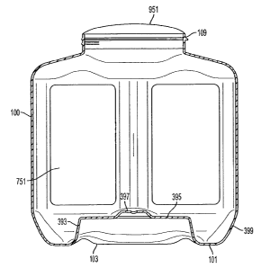
[030] As can be seen in FIG. 3, the center of the base (101) includes a
recessed portion (103)
which, in the depicted embodiment, comprises a cylinder having generally
vertical walls (393)
and its upper end closed by a generally horizontal cap (395). The cap (395)
also includes a
further depression (397) which comprises a second recessed portion into the
volume (751) of the
container (100). The walls (393) will generally connect in a smoothly curving
fashion to the
base (101) generally by curves which curve smoothly outward in a convex
fashion from the
interior (751) of the container (100) into the hollow interior (399) of the
recessed portion (103).
The cap (395) will also generally connect to the walls (393) in a smooth
fashion, however, this is
likely to involve a tighter concave curve providing the inside with a sharper
edge.
[031] The recessed portion (103) will generally have a diameter which is
slightly larger than the
diameter of the neck (109) of the container. Specifically, the diameter of the
recessed portion
(103) will generally be close to, but still slightly larger than the external
diameter of the lid (951)
as can be best seen in FIG. 3. The height of the walls (393) will generally be
similar, but slightly
larger than the height of the neck (109). Specifically, the recessed portion
(103) will generally
have a height generally equal to the height of the neck (109) and lid (901)
combination when the
lid is placed on the neck in the standard fashion.
[032] In the blow molding process of the present application which is utilized
to create
recessed-base containers similar to the container depicted in FIG. 3, the
process generally begins
with a plastic resin hot tube called a parison or a preform. The parison is
placed within a split
mold with a hollow cavity. The mold sides (and sometimes the bottom) are then
clamped
together, thus pinching and sealing the parison tube. Air is then blown into
the tube, resulting in
CA 02791596 2012-10-03
=
an expansion of the hot resin wall into the shape of the cavity. Generally,
the neck of the
container neck serves as the connection between the bottle body and the source
of air which is
used to inflate the container. Generally, these types of containers are formed
using high speed
stretch blow molding techniques as known to those of ordinary skill which
provide additional
strength to the plastic which forms the container.
[033] Because blow-molding techniques generally require that the structure to
be formed
comprise a hollow balloon which is then pushed or molded into shape, the
process is particularly
well suited to hollow containers as the preform is inflated internally and
pushed outward into the
structure of the mold. The mold therefore is formed with an internal negative
of the object to be
formed. Thus, any recessed portions of the container have corresponding
protrusions on the
mold. This process is demonstrated in FIG. 4, which shows, step-by-step, an
embodiment of the
blow molding process of the current application and the resultant finished
bottle.
[034] Generally, as noted previously, in order to release the finalized
container traditional two-
piece molds will break apart into two halves which are arranged vertically
side-by-side. In this
way, once the preform has been formed into the mold, the two halves open which
pulls the
negative internal surface of the mold from the external surface of the
container. From this point,
the container can be blown off the air source to release it.
[035] As should be apparent, the container of FIG. 3 cannot be ejected from
the traditional
blow mold with two halves as the recessed base portion would serve to provide
part of the mold
which is in the way to the ejection. Specifically, the recessed portion cannot
be negatively
formed on either half of the mold as the negative space inside the recessed
portion is not
connected to any side of the container by further negative space. That is, the
protrusion
necessary to form the base cannot be formed on either half of the mold. Doing
so would result in
11
CA 02791596 2012-10-03
=
the mold half being inseparable from the finalized container as the portion of
the recessed area
that is over the mold would cause the container to be transported with that
half of the mold. In
an extreme case, the mold attempting to release would damage the base of the
container.
[036] It has been traditionally understood in the art of blow molding that any
negative recessed
spaces in the container need to be formed from the sides of the container.
Thus, in order to form
a hollow center of the base, two part molds traditionally provide for a
relatively small center
space with a relatively wide opening leading to it. The molds may also be
provided in multiple
pieces; i.e., in a three-part mold to create relatively small base indents.
This is the manner that a
traditional petal-footed container was molded in the prior art, there can be a
central recesses, but
that recess includes negative access spaces which serve to create the petal
shape of the base
allowing access from both the sides and the base,
[037] The container of FIG. 3, however, does not include the negative space
approaching the
central recess (103) and as discussed in the copending application 13/087,883,
rather it utilizes
the space about the base both to rest on a lower container's shoulder and to
provide the container
with a solid footing. Thus, it would be undesirable to dramatically increase
the size of the
recessed portion so as to allow it to access at least one side of the
container as in a petal-footed
container.
[038] Instead, the container can be formed utilizing an embodiment of the blow
mold shown in
FIG. 4. In the depicted blow mold (300) the mold itself (300) comprises three
pieces: a base
(301), a left half (303), and a right half (305). The left half (303) and
right half (305) are of a
standard design of a traditional blow mold tool known to those of ordinary
skill in the art. As
such, the left half (303) and right half (305) will provide tooling and
structure for the vertical
walls (393) of the sides of the blow molded container.
12
CA 02791596 2012-10-03
[039] The base (301) is designed to come up from the bottom of the molding
machine and
smoothly connect with the left half (303) and right half (305) to form the
depicted three-piece
mold (300) in a closed position. The connection of the left half (303), right
half (305) and base
(301) of the molding machine from the open position to the closed position can
been seen in step
1 (401) and step 2 (402) of FIG. 4. As seen from FIG. 4, in the depicted
embodiment, when in
the closed position (402), the left half (303), right half (305) and base
(301) of the mold (300)
generally smoothly connect together with no substantial voids there-between.
Generally, in this
closed position (402) the mold (300) generally resembles a square or cube-like
structure.
[040] The base (301) of the depicted three piece mold (300) further includes a
push-up portion
or ram (306). This push-up portion (306) is placed within a chamber of the
base (301).
Generally, this push-up portion (306) is a retractable mechanism, retracting
and protruding in a
generally vertical manner with respect to the internal negative space of the
mold (300). Stated
differently, the push-up portion, when in the protruded position (depicted in
step 2 (402) of FIG.
4) protrudes into the negative shape of the mold that forms the base (101) of
the container¨ the
push-up portion (306) corresponds to the recessed portion(s) of the base (101)
of the container.
Thus, this push-up portion (306) of the mold (300) is used to form the base
(101) of the container
and the internal recessed portion(s) of the base (101) of the container.
[041] Notably, the push-up portion (306) is generally not a rigid mold part of
the base (301)
but, instead, comprises a mold (300) element which is moveable relative to the
base (301). The
vertical movement of the push-up portion relative to the base (301) and the
rest of the mold (300)
in the closed position (402) is generally created by any suitable mechanical
force or mechanism
known to those of ordinary skill in the art including, but not limited to,
cams, air or hydraulic
cylinders.
13
CA 02791596 2012-10-03
[042] In operation, the mold (300) will generally operate as follows, as
depicted in FIG. 4. In a
first step (401), the left half (303), right half (305) and base (301) are in
the initial, open position.
In this initial, open position the mold left half (303) and right half (305)
are open, the base is
down and the push-up portion (306) is down in the recessed position in the
base (301). In a
second step (402), the left half (303), right half (305) close and the base
(301) moves up (with
the push-up portion (306) in the base (301) still in the down, recessed
position) into the closed
position of the mold (300). Notably, the exact order of the pieces coming
together in this second
step (402) is variable, generally any manner in which the pieces can come
together from the open
position (401) to the closed position (402) is contemplated.
[043] Once all three pieces of the mold (300) are positioned in the closed
position, the blow
molding of the preform into the container will begin. Generally, any suitable
method of blow
molding is contemplated in this application. Further, in this second step
(402) the push-up (306)
moves up into a protruded position simultaneously as the preform is blow
molded. This
simultaneous blow molding and protrusion of the push-up portion (306) alters
the forces and
pressures in container formation which create the base (101), allowing for the
clear and defined
formation of the container's vertical walls (393), horizontal cap (395) and
base (101).
Specifically, as the air is being pushed into the preform, the preform will
generally be pushed
radially out from a centralized point within the preform. In this arrangement,
the base (101) will
initially be formed at the center (as it is the closest point to the air
source) and the outer bottom
corners of the base (101) will generally be the last portion of the base to
form.
[044] It should be apparent that if the moveable portion (306) was positioned
in its highest
(furthest into the mold cavity) position at the start of the blow process, the
preform expansion
would tend to "bridge" the channel (307) which is used to form the foot of the
container.
14
CA 02791596 2012-10-03
Specifically, the material of the preform would first contact the ram (306).
As it flowed out
toward the channel (307), the material would be more inclined to first flow
horizontally across
the channel (307) bridging the channel (307). It would then require a very
large amount of time
and air pressure, to get the bridge of prefotill material to push down into
the channel and assume
the correct shape.
[045] The issue is quite simple, because the air is generally applied to the
preform at an area
above the center of the base in a relatively radial fashion, there is usually
not enough vertical
force to push the material into the channel (307) compared to the horizontal
force to push the
base (101) into the side wall.
[046] In order to deal with this problem, the ram (306) is designed to rise as
the preform is
expanding. Specifically, the push-up (306) will serve to provide a mechanical
force to the base
in a vertical direction. This serves to force the material of the preform to
flow around the comer
(309) and helps to make sure that the material is pushed into the channel
(307). In effect, the
ram (306) provides an additional molding force (in addition to the air
pressure) to serve to direct
the preform material into the correct position and form the base (101) of the
container.
[047] The exact timing of the movement of the push-up (306) compared with the
blowing from
air will depend on the specific size of the container, the size and depth of
the recessed portion
(103) and the blow molding techniques being used. However, it will often be
the case that the
push-up will be maintained in it lowest (or "flush") position (403) until the
preform has had
material pushed close to or beyond the comer (309). IN this way, the
mechanical stress serves
directly to push the material into the channel. However, in alternative
embodiments, the push-up
(306) can extend as soon as the preform material contacts the push-up surface
(311) thus
CA 02791596 2012-10-03
providing a counter motion to the air blow motion on the base (101) and
providing for increased
flow of material over the surface (311) and into the channel (307).
[048] After the expansion of the preform in the negative space of the mold
(300) to form the
container, in a third step (403) the push-up portion (306) in the base (301)
will generally be
retracted from the base (301) of the mold (300) to clear the recessed base of
the container. As
seen in step 3 (403) of FIG. 4, this retractable push-up portion (306) of the
base (301) of the
mold (300) retracts from the blow molded, formed container and the left half
(303), right half
(305) and base (301) of the three-part mold (300) while the three-part mold
(300) is still together
positioned in the closed form. This reduces the mechanical stress and high
pressure which can
be exerted on the feet of the container that would be present in previous
methods and
manufacturing processes for blow molding.
[049] Specifically, as the push-up (306) drops first, the inner wall (393) is
released before the
outer wall (399) of the base. This sequential release provides that less force
is applied to the
base (101) as the bottom (301) of the mold (300) is removed. Specifically, the
force of
separation of the base (101) from the mold is separated into two steps of
reduced force, instead
of a single step with significantly increased force. This can reduce the
likelihood of mold
removal causing deformation of the container.
[050] In a fourth step (404), once the push-up portion (306) has been
withdrawn, the left half
(303) and the right half (305) will open in the standard fashion and the base
(301) will withdraw
downward, returning the mold to the initial position, allowing the container
to be ejected in a
standard fashion as is known to those of ordinary skill.
[051] As demonstrated in FIG. 4, the push-up portion (306) will often pull
away from the
container and move relative to the base (301). In other words, when the base
(301) retracts it
16
CA 02791596 2012-10-03
does so in two discreet steps. First, the push-up portion (306) retracts from
the closed, molding
position in step 3 (403). At this time, the base (301) is still up. Then, in
step 4 (404), the base
(301) falls down from the closed molding position to the initial position.
[052] As should be apparent from the above, this two-part retraction of the
base (301) of the
.. mold (300) frees the recessed portion of the base (101) of the container
prior to freeing the rest of
the base (101) of the container. This two-part movement thus reduces the high
pressure and
mechanical stress exerted on the container base (101) when the container is
released, thereby
reducing the probability that the container will be stripped and/or
disoriented from the raised step
and the rest of the bottom mold cavity retracting simultaneously. Also, the
simultaneous
protraction of the push-up portion (306) and the expansion of the preform
alters the forces
utilized to create the container, making it easier to form a container with
defined legs and sharper
angles at the recessed base.
[053] In a still further embodiment, as the base (301) retracts in step 4
(404), the push-up
portion (306), can actually serve to push upwards relative to the rest of the
base (301). This can
serve to provide a push to clear the container from the base (301) should the
container still be in
contact with the base (301) as the container is cleared from the mold (300)
and, thus, can further
assist in ejecting the container from the mold and inhibiting deformation.
[054] The methodology and molds discussed above provide for particular
advantage in making
containers such as that shown in FIG. 3 due to the depth and size of the
recess (103) and the fact
.. that access to the recess from the sides is generally undesirable. However,
it should be
recognized that a mold having a push-up portion can be used in a variety of
other container
applications. In an embodiment, the push up can be used to form a container
with a recess base
17
CA 02791596 2012-10-03
portion (103) in a two part mold, a process that was previously impossible as
the ram (306) can
be retracted prior to the mold opening.
[055] The push-up (306) can also be used to provide for decorative shapes for
the base of
containers, or for the sides or tops of objects, depending on how the object
is oriented during
blow molding. Specifically, this methodology and molding mechanism may be used
to form a
recess, and even a very deep recess, on the portion of the object formed on
the base of the mold.
This was something that was not previously possible and therefore often
resulted in objects
having to be formed in a less than ideal orientation. This need to orient to
avoid a recess on the
base is eliminated which can provide for additional efficiency and options in
mold manufacture.
[056] Further, while FIG. 4 contemplates only a single retractable portion
(306), one of
ordinary skill would understand that alternative embodiments may utilize
multiple push ups
(306). This may be separate, may partially overlap, or may be nested within
each other to
provide for recesses with a variety of different shapes instead of just the
cylindrical recess (103)
shown in FIG. 3.
[057] While the invention has been disclosed in connection with certain
preferred
embodiments, this should not be taken as a limitation to all of the provided
details.
Modifications and variations of the described embodiments may be made without
departing from
the spirit and scope of the invention, and other embodiments should be
understood to be
encompassed in the present disclosure as would be understood by those of
ordinary skill in the
art.
18