Note: Descriptions are shown in the official language in which they were submitted.
CA 02791601 2012-10-02
30977-6
BLANK AND CONTAINER HAVING AN ANTI-
BUCKLING MECHAN ISM
BACKGROUND OF THE INVENTION
[0001] The embodiments described herein relate generally to an anti-
buckling mechanism for a container and, more particularly, to an anti-buckling
mechanism for use with a clamshell-type container.
[0002] At least some known containers are clamshell-type containers
having a lower tray and an upper cover connected at a fold line. At least some
known
trays and covers include walls that taper outward from a fold line toward a
free edge.
Such tapering may cause the container to buckle at the fold line when the
container is
opened and closed. As such, at least some known containers include anti-
buckling
features in the tray, the cover, and/or along the fold line.
[0003] One known anti-buckling feature in U.S. Pat. No. 5,332,147
includes a first cut along a hinge line joining the tray and the cover, and a
second cut
in a back panel positioned to one side of the first cut, wherein the second
cut is a
continuous curve having a first end point located in the back panel and a
second end
point intersecting the first cut. A known anti-buckling feature in U.S. Pat.
No.
5,221.040 includes a first cut along a hinge line joining the tray and the
cover, and a
second cut in a back panel above the first cut, wherein the first cut is
continuous and
approximately half the length of the hinge line. Another known anti-buckling
feature
in U.S. Pat. No. 5,221,040 includes a cut along a hinge line joining the tray
and the
cover, and at least one cut in a back panel that is generally coextensive with
the hinge
line cut. However, none of these known anti-buckling features includes a
series of
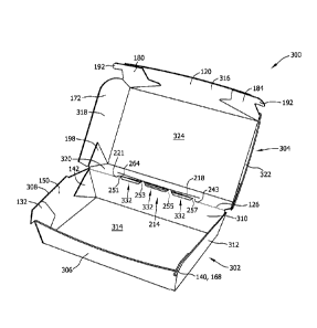
straight lines and/or includes a series of straight cut lines that extends
more than half
the length of the hinge line.
-1-
CA 02791601 2012-10-02
30977-6
BRIEF DESCRIPTION OF THE INVENTION
[0004] In one aspect, a blank of sheet material for forming a
container is provided. The blank includes a tray panel assembly, a cover panel
assembly, a fold line connecting the tray panel assembly and the cover panel
assembly, and an anti-buckling mechanism interrupting the fold line. The anti-
buckling mechanism includes a series of cuts positioned at least partially
below the
fold line in the tray panel assembly. The series of cuts extends more than
half a
length of the fold line. Each cut of the series of cuts is substantially
straight. The
anti-buckling mechanism further includes an upper cut line defined in the
cover panel
assembly.
[0005] In another aspect, a container formed from a blank of sheet
material is provided. The blank includes a lower tray, an upper cover, a fold
line
connecting the lower tray and the upper cover, and an anti-buckling mechanism
interrupting the fold line. The anti-buckling mechanism includes a series of
cuts
positioned at least partially below the fold line in the lower tray. The
series of cuts
extends more than half a length of the fold line. Each cut of the series of
cuts is
substantially straight. The anti-buckling mechanism further includes an upper
cut line
defined in the upper cover.
BRIEF DESCRIPTION OF THE DRAWINGS
[0006] Figs. 1-17 show exemplary embodiments of the blanks and
containers described herein.
[0007] Fig. 1 is a top view of an interior surface of an exemplary
blank of sheet material for forming an exemplary anti-buckle container.
[0008] Fig. 2 is a back view of an exemplary anti-buckle container
formed from the blank shown in Fig. 1 in a closed configuration.
[0009] Fig. 3 is a perspective view of the anti-buckle container
shown in Fig. 2 in an open configuration.
-2-
CA 02791601 2012-10-02
30977-6
[0010] Fig. 4 is a close-up perspective view of an interior of the anti-
buckle container shown in Fig. 3.
[0011] Fig. 5 is a blown-up view of the anti-buckle container shown
in Fig. 4 taken at area 5.
[0012] Fig. 6 is a close-up perspective view of an exterior of the anti-
buckle container shown in Fig. 3.
[0013] Fig. 7 is a top view of an interior surface of a first alternative
blank of sheet material for forming a first alternative anti-buckle container.
[0014] Fig. 8 is a top view of an interior surface of a second
alternative blank of sheet material for forming a second alternative anti-
buckle
container.
[0015] Fig. 9 is a back view of an exemplary anti-buckle container
formed from the blank shown in Fig. 8 in the closed configuration.
[0016] Fig. 10 is a top view of an interior surface of a third
alternative blank of sheet material for forming a third alternative anti-
buckle
container.
[0017] Fig. 11 is a back view of an exemplary anti-buckle container
formed from the blank shown in Fig. 10 in the closed configuration.
[0018] Fig. 12 is a perspective view of an interior of the anti-buckle
container shown in Fig. 11 in an open configuration.
[0019] Fig. 13 is a perspective view of an exterior of the anti-buckle
container shown in Fig. 12 in the open configuration.
[0020] Fig. 14 is a top view of an interior surface of a fourth
alternative blank of sheet material for forming a fourth alternative anti-
buckle
container.
-3-
CA 02791601 2012-10-02
30977-6
[0021] Fig. 15 is a back view of an exemplary anti-buckle container
formed from the blank shown in Fig. 14 in the closed configuration.
[0022] Fig. 16 is a perspective view of an interior of the anti-buckle
container shown in Fig. 15 in an open configuration.
[0023] Fig. 17 is a perspective view of an exterior of the anti-buckle
container shown in Fig. 16 in the open configuration.
DETAILED DESCRIPTION OF THE INVENTION
[0024] The containers described herein are configured to contain a
product, such as a food product, therein. Each container includes an anti-
buckling
mechanism that facilitates preventing rear panels of the container from
buckling along
a fold line connecting the rear panels, and consequently, facilitates opening
and
closing the clamshell-type container. The anti-buckling mechanism can be
defined in
any suitable container having an upper rear panel and a lower rear panel
connected
along a fold line, and is not limited to being included on the clamshell-type
containers
described herein.
[0025] Clamshell containers formed from a single blank of sheet
material and methods for constructing the container are described herein. In
one
embodiment, the blanks are fabricated from a paperboard material. The blanks,
however, may be fabricated using any suitable material, and therefore are not
limited
to a specific type of material. In alternative embodiments, the blanks are
fabricated
using cardboard, plastic, fiberboard, paperboard, foamboard, corrugated paper,
mineral-filled plastic, and/or any suitable material known to those skilled in
the art
and guided by the teachings herein provided.
[0026] In an example embodiment, the clamshell container includes
at least one marking thereon including, without limitation, indicia that
communicates
the product stored in the tray, a manufacturer of the product, and/or a seller
of the
product. For example, the marking may include printed text that indicates a
product's
name and briefly describes the product, logos and/or trademarks that indicate
a
-4-
CA 02791601 2012-10-02
30977-6
manufacturer and/or seller of the product, and/or designs and/or ornamentation
that
attract attention. "Printing," "printed," and/or any other form of "print" as
used herein
may include, but is not limited to including, ink jet printing, laser
printing, screen
printing, pen and ink, painting, offset lithography, flexography, relief
print,
rotogravure, dye transfer, and/or any suitable printing technique known to
those
skilled in the art and guided by the teachings herein provided. In another
embodiment, the clamshell container is void of markings, such as, without
limitation,
indicia that communicates the product, a manufacturer of the product and/or a
seller
of the product.
[0027] The containers described herein can have various overall
dimensions and still include the exemplary anti-buckling mechanisms. For
example,
the containers can range from a smaller container, being approximately 3
inches wide
by varying depths, to a larger container, being approximately 10 inches wide
by
varying depths. These various-dimensioned containers would still include the
general
anti-buckling features described herein, but in the case of the larger
containers may
include additional hinge tab cut lines and fingers, as compared to smaller
containers.
For example, cartons having a width ranging between about 3 inches and about 4
inches may include two hinge tab cut lines that define three fingers; cartons
having a
width ranging between about 4 inches and about 5 inches may include three
hinge tab
cut lines that define four fingers; cartons having a width ranging between
about 5
inches and about 7 inches may include four hinge tab cut lines that define
five fingers;
and cartons having a width ranging between about 7 inches and about 10 inches
may
include five hinge tab cut lines that define six fingers. The hinge tab cut
lines and
fingers are described in more detail below with respect to Fig. 1. In
addition, in
various-dimensioned containers, a length of each individual hinge tab cut line
typically ranges between about 1 inch to about 1 1/4 inches. Center tab cut
line(s)
have a length that is substantially equal to, or greater than by up to
approximately
15%, outer hinge tab cut lines. All other dimensions discussed herein would be
substantially consistent over the range of differently sized of containers.
-5-
CA 02791601 2012-10-02
30977-6
[0028] Fig. 1 is a top view of an interior surface of an exemplary
blank 100 of sheet material for forming an exemplary embodiment of an anti-
buckle
container, such as container 300 (shown in Figs. 2-6). Blank 100 has a first
or interior
surface 102 and an opposing second or exterior surface 104. Further, blank 100
defines a first edge 106 and an opposing second edge 108. In one embodiment,
blank
100 includes, in series from first edge 106 to second edge 108, a lower front
panel
110, a bottom panel 112, a lower rear panel 114, an upper rear panel 116, a
top panel
118, and an upper front panel 120 coupled together along preformed, generally
parallel, fold lines 122, 124, 126, 128, and 130, respectively. Fold lines
122, 124,
126, 128, and/or 130, as well as other fold lines and/or hinge lines described
herein,
may include any suitable crease, line of weakening, and/or line of separation
known
to those skilled in the art and guided by the teachings herein provided. More
specifically, lower front panel 110 extends from first edge 106 to fold line
122,
bottom panel 112 extends from lower front panel 110 along fold line 122, lower
rear
panel 114 extends from bottom panel 112 along fold line 124, upper rear panel
116
extends from lower rear panel 114 along fold line 126, top panel 118 extends
from
upper rear panel 116 along fold line 128, and upper front panel 120 extends
from top
panel 118 along fold line 130 to second edge 108.
[0029] A first lower front coupling tab 132 extends from a first side
edge of lower front panel 110 along a fold line 134, and a second lower front
coupling
tab 136 extends from a second side edge of lower front panel 110 along a fold
line
138. Each lower front coupling tab 132 and 136 includes a closure hook 140
extending therefrom. Similarly, a first lower rear coupling tab 142 extends
from a
first side edge of lower rear panel 114 along a fold line 144, and a second
lower rear
coupling tab 146 extends from a second side edge of lower rear panel 114 along
a fold
line 148.
[0030] A first lower side panel 150 extends from a first side edge of
bottom panel 112 at a fold line 152, and a second lower side panel 154 extends
from a
second side edge of bottom panel 112 at a fold line 156. A cut line 158
separates first
lower side panel 150 from first lower front coupling tab 132, and a cut line
160
-6-
CA 02791601 2012-10-02
30977-6
separates first lower side panel 150 from first lower rear coupling tab 142.
Similarly,
a cut line 162 separates second lower side panel 154 from second lower front
coupling
tab 136, and a cut line 164 separates second lower side panel 154 from second
lower
rear coupling tab 146. Each lower side panel 150 and 154 includes a free edge
166
that partially defines a closure hook 168 each having a similar shape to
closure hooks
140. Free edge 166 further defines a cutout 170 configured to allow container
300 to
be positioned in a closed configuration and/or vent contents of container 300.
[0031] A first upper side panel 172 extends from a first side edge of
top panel 118 at a fold line 174, and a second upper side panel 176 extends
from a
second side edge of top panel 118 at a fold line 178. A first upper front
coupling tab
180 extends from a front edge of first upper side panel 172 along a fold line
182, and
a second upper front coupling tab 184 extends from a front edge of second
upper side
panel 176 along a fold line 186. A cut line 188 separates first upper front
coupling tab
180 from upper front panel 120, and a cut line 190 separates second upper
front
coupling tab 184 from upper front panel 120. Each upper front coupling tab 180
and
184 includes a closure projection 192 defined along a free edge 194 thereof. A
notch
196 is defined adjacent to closure projection 192 and is configured to receive
a pair of
closure hooks 140 and 168 when container 300 is formed and in the closed
configuration. Alternatively, blank 100 includes any suitable closure and/or
locking
mechanism that enables container 300 to be secured in the closed
configuration. For
example, the locking mechanism, such as a slot (not shown) defined along fold
line
130, in top panel 118, and/or in upper front panel 120 and a tab (not shown)
extending
from lower front panel 110 and configured to be inserted into the slot, such
as the tab-
and-slot locking mechanism shown in Figs. 7 and 10.
[0032] In the exemplary embodiment, a first upper rear coupling tab
198 extends from a first side edge of upper rear panel 116 along a fold line
200, and a
second upper rear coupling tab 202 extends from a second side edge of upper
rear
panel 116 along a fold line 204. A cut line 206 separates first upper side
panel 172
from first upper rear coupling tab 198, and a cut line 208 separates second
upper side
panel 176 from second upper rear coupling tab 202. Panels 110, 112, 114, 150,
and
-7-
CA 02791601 2012-10-02
30977-6
154 and tabs 132, 136, 142, and 146 define a bottom tray panel assembly 210,
and
panels 116, 118, 120, 172, and 176 and tabs 180, 184, 198, and 202 define atop
cover
panel assembly 212. Bottom tray panel assembly 210 and top cover panel
assembly
212 are connected along fold line 126.
[0033] An anti-buckling mechanism 214 is defined adjacent fold line
126 and in rear panels 114 and 116. More preferably, anti-buckling mechanism
214
includes a series 216 of cuts interrupting fold line 126 and an upper cut line
218
defined in upper rear panel 116. Series 216 and upper cut line 218 are
configured to
prevent rear panel 114 and/or 116 from buckling at fold line 126 when
container 300
is transitioned between an open configuration and the closed configuration.
Further,
series 216 and upper cut line 218 are symmetric about an axis 220 that is
substantially
perpendicular to fold lines 124 and 128 and positioned at a center of rear
panels 114
and 116. As such, series 216 and upper cut line 218 are symmetric about a
central
vertical axis 220.
[0034] In the exemplary embodiment, series 216 has a length L1 that
is longer than half a length L2 of fold line 126. Similarly, upper cut line
218 has a
length L3 that is longer than half length L2 of fold line 126. In the
exemplary
embodiment, length L1 is substantially equal to or longer than length L3. In
the
embodiment shown in Fig. 1, length 1,1 is longer than length L3 by about 1/4
inch.
Series 216 includes a leading horizontal cut 221, a first upward cut 222, a
first
downward cut 224, a first horizontal cut 226, a second upward cut 228, a
second
downward cut 230, a second horizontal cut 232, a third upward cut 234, a third
downward cut 236, a third horizontal cut 238, a fourth upward cut 240, a
fourth
downward cut 242, and a trailing horizontal cut 243. As used herein, the term
"upward" refers to a direction from lower rear panel 114 toward upper rear
panel 116
at a non-orthogonal angle to fold line 126, and the term "downward" refers to
a
direction from upper rear panel 116 toward lower rear panel 114 at a non-
orthogonal
angle to fold line 126. In a particular embodiment, each upward cut 222, 228,
234,
and 240 and each downward cut 224, 230, 236, and 242 is at substantially 45
to
horizontal cuts 221, 226, 232, 238, and 243.
-8-
CA 02791601 2012-10-02
30977-6
[0035] A length L4 is defined between an end of first downward cut
224 and an end of fourth upward cut 240. Length L4 is longer than half of
length L2.
Further, length L3 is substantially equal to or longer than length L4. In the
embodiment shown in Fig. 1, length L3 is longer than length L4 by, for
example, about
1/4 inch. Further, each horizontal cut is substantially horizontal within
manufacturing
tolerances. Each horizontal cut 221, 226, 232, 238, and 243 is offset from
fold line
126 into lower rear panel 114. More specifically, the offset from fold line
126 ranges
between about 0.89% and about 2.5% of a height of lower rear panel 114. In the
embodiment shown in Fig. 1, each horizontal cut 221, 226, 232, 238, and 243 is
offset
from fold line 126 by about 1/64 inch. Cuts 221, 222, 224, 226, 228, 230, 232,
234,
236, 238, 240, 242, and 243 are configured to define at least two continuous
cut lines,
as described in more detail below. Such continuous cut lines are also
described herein
as hinge tab cut lines.
[0036] First upward cut 222 and first downward cut 224 have a first
gap 244 defined therebetween such that a portion of material separates first
upward
cut 222 and first downward cut 224, second upward cut 228 and second downward
cut 230 have a second gap 246 defined therebetween such that a portion of
material
separates second upward cut 228 and second downward cut 230, third upward cut
234
and third downward cut 236 have a third gap 248 defined therebetween such that
a
portion of material separates third upward cut 234 and third downward cut 236,
and
fourth upward cut 240 and fourth downward cut 242 have a fourth gap 250
defined
therebetween such that a portion of material separates fourth upward cut 240
and
fourth downward cut 242. In particular embodiments, each gap 244, 246, 248,
and
250 has a length ranging between about 1/32 inch and about 3/16 inch. In the
embodiment shown in Fig. 1, each gap 244, 246, 248, and 250 has a length of
about
1/16 inch.
[0037] First downward cut 224, first horizontal cut 226, and second
upward cut 228 define a first continuous cut line 252; second downward cut
230,
second horizontal cut 232, and third upward cut 234 define a second continuous
cut
line 254; and third downward cut 236, third horizontal cut 238, and fourth
upward cut
-9-
CA 02791601 2012-10-02
30977-6
240 define a third continuous cut line 256. A finger 251, 253, 255, and 257 is
defined
by the portions of material between each adjacent continuous cut line 252,
254, and
256. Each finger 251, 253, 255, and 257 each have a height configured to cause
arcing of a strap 264 with respect to the remainder of upper rear panel 116,
arcing of
upper rear panel 116 upward toward lower rear panel 114, and/or arcing of
lower rear
panel 114 upward toward upper rear panel 116 in the open position, as
described in
more detail below. In particular embodiments, each finger 251, 253, 255, and
257 has
a height ranging between about 1/16 inch and about 1/4 inch. In the embodiment
shown in Fig. 1, each finger 251, 253, 255, and 257 has a height of about 1/8
inch.
Accordingly, the height of fingers 251, 253, 255, and 257 ranges between about
7%
and about 20% of a height of upper rear panel 116.
[0038] Upper cut line 218 includes a first end 258, a second end 260,
and a mid-point 262 approximately half way between first end 258 and second
end
260. Upper cut line 218 is arcuate between ends 258 and 260 such that mid-
point 262
is nearer series 216 than ends 258 and 260 are. Some alternative embodiments
of
anti-buckling mechanism 214 are shown in Figs. 7-9. In the exemplary
embodiment,
upper cut line 218 is positioned a distance from fold line 126 at mid-point
262. In the
embodiment shown in Fig. 1, upper cut line 218 is positioned about 1/4 inch
from fold
line 126 at mid-point 262. As such, strap 264 of material is defined between
upper
cut line 218 and series 216. Strap 264 is configured to move with respect to
the
remainder of upper rear panel 116 during the opening and closing process, as
described in more detail herein.
[0039] As discussed above, the exemplary dimensions are
substantially consistent for containers having a bottom panel width of between
about
3 inches and about 10 inches, while the number of gaps and continuous cut
lines
and/or the number of fingers depends on the size of the blank. For example, a
smaller
blank may have three fingers, and a larger blank may have five fingers.
However, the
height of the fingers, the length of the gaps, the offset from fold line 126,
and the
position of upper cut line 218 would be substantially the same, as discussed
above.
An example of a blank having three fingers is shown in Figs. 8 and 9.
-10-
CA 02791601 2012-10-02
30977-6
[0040] Fig. 2 is a back view of an exemplary anti-buckle container
300 formed from blank 100 (shown in Fig. 1) in the closed configuration. Fig.
3 is a
perspective view of container 300 in the open configuration. Fig. 4 is a close-
up
perspective view of container 300. Fig. 5 is a blown-up view of container 300
taken
at area 5 in Fig. 4. Fig. 6 is a close-up perspective view of an exterior of
container
300. Container 300 includes a bottom tray 302 and a top cover 304 connected to
each
other at fold line 126 and/or anti-buckling mechanism 214. Tray 302 includes a
lower
front wall 306, a first lower side wall 308, a lower rear wall 310, a second
lower side
wall 312, and a bottom wall 314. Cover 304 includes an upper front wall 316, a
first
upper side wall 318, an upper rear wall 320, a second upper side wall 322, and
a top
wall 324. In the closed configuration, lower front wall 306 and upper front
wall 316
form a front wall (not shown), first lower side wall 308 and first upper side
wall 318
form a first side wall 326, lower rear wall 310 and upper rear wall 320 form a
rear
wall 328, and second lower side wall 312 and second upper side wall 322 form a
second side wall 330.
[0041] In the exemplary embodiment, first lower side wall 308
includes first lower front coupling tab 132 and first lower rear coupling tab
142
coupled to first lower side panel 150. Similarly, second lower side wall 312
includes
second lower front coupling tab 136 (shown in Fig. 1) and second lower rear
coupling
tab 146 (shown in Fig. 1) coupled to second lower side panel 154 (shown in
Fig. 1).
Closure hooks 140 and 168 align with each other. Upper front wall 316 includes
first
upper front coupling tab 180 and second upper front coupling tab 184 coupled
to front
panel 120. Upper front wall 316 further includes closure projection 192
extending
from each side thereof. First upper side wall 318 includes first upper rear
coupling
tab 198 coupled to first upper side panel 172, and second upper side wall 322
includes
second upper rear coupling tab 202 (shown in Fig. 1) coupled to second upper
side
panel 176 (shown in Fig. 1).
[0042] Referring to Fig. 2, in the closed configuration rear walls 310
and 320 are substantially in contact with each other at series 216. Referring
to Figs.
3-6, in the open configuration, openings 332 are defined at cut lines 252,
254, and/or
-11-
CA 02791601 2012-10-02
30977-6
256 and four substantially wedge-shaped fingers 251, 253, 255, and 257 of
material
are defined between openings 332. Further, an upper opening 336 may be defined
at
upper cut line 218. Openings 332 and/or upper opening 336 enable container 300
to
be transitioned between the closed configuration and the open configuration
without
buckling at lower rear wall 310, upper rear wall 320, and/or fold line 126 by
allowing
strap 264 to move with respect to rear walls 310 and/or 320.
[0043] More specifically, as shown in Figs. 3 and 4, fingers 253 and
255 push strap 264 upwards causing strap 264 to become arcuately-shaped from
leading horizontal cut 221 to trailing horizontal cut 243. Because of the
arcuate shape
of strap 264, a central opening 332 and upper opening 336 have a width that is
largest
proximate to axis 220 (shown in Fig. 1). As shown in Figs. 5 and 6, strap 264
is
pushed upward relative to upper rear wall 320 by fingers 253 and 255. In other
words, fingers 253 and 255 are configured to push strap 264 upward from the
remaining portion of upper rear wall 320 to prevent buckling of container 300
at rear
walls 310 and 320.
[0044] Further, fingers 251, 253, 255, and/or 257 pull lower rear wall
310 upwards towards upper cover 304 as container 300 is opened. More
specifically,
tray 302 is rotating with respect to cover 304 at gaps 244, 246, 248, and 250
rather
than at fold line 126, and the higher fold over action causes arcing of lower
rear wall
310 and/or upper rear wall 320. Further, although there may be a fold line
present at
each gap 244, 246, 248 and 250, the material of blank 100 rolls upward on
itself to its
weakest point at each gap 244, 246, 248 and 250 thereby creating a soft bend,
rather
than a sharp fold or crease, in the material. The rolling of the material
facilitates
eliminating binding in rear wall 328 because the soft edge and the bend cause
separation within the material.
[0045] Fig. 7 is a top view of an interior surface of a first alternative
blank 400 of sheet material for forming a first alternative anti-buckle
container.
Blank 400 is substantially similar to blank 100 (shown in Fig. 1), except
blank 400
includes a substantially straight upper cut line 402 and a tab-and-slot
locking
-12-
CA 02791601 2012-10-02
30977-6
mechanism. The tab-and-slot locking mechanism is described in more detail with
respect to Fig. 10. Further, blank 400 includes a different configuration of
coupling
tabs, as described in more detail with respect to Fig. 10. As such, components
shown
in Fig. 7 are labeled with the same reference numbers used in Fig. 1. In the
exemplary embodiment, upper cut line 402 is substantially straight between a
first end
404 and a second end 406 through a mid-point 408. As such, upper cut line 402
is
substantially linear.
[0046] Fig. 8 is a top view of an interior surface of a second
alternative blank 450 of sheet material for forming a second alternative anti-
buckle
container. Fig. 9 is a back view of an exemplary anti-buckle container 470
formed
from blank 450 in the closed configuration. Referring to Fig. 8, blank 450 is
substantially similar to blank 100 (shown in Fig. 1), except blank 450
includes a series
452 of cuts that omits third horizontal cut 238, fourth upward cut 240, fourth
gap 250,
and fourth downward cut 242 (all shown in Fig. 1). As such, components shown
in
Figs. 8 and 9 are labeled with the same reference numbers used in Figs. 1-4.
Referring to Fig. 9, when container 470 is formed, three substantially wedge-
shaped
fingers 251, 253, and 255 of material are defined in rear wall 328 by series
452.
[0047] In the exemplary embodiment, series 452 and upper cut line
218 are symmetric about axis 220. As such, second finger 253 is positioned on
axis
220. Further, it should be understood that, although arcuate upper cut line
218 is
shown in Figs. 8 and 9, blank 450 and container 470 can include substantially
straight
upper cut line 402, as shown in Fig. 7.
[0048] Fig. 10 is a top view of an interior surface of a third
alternative blank 500 of sheet material for forming a third alternative anti-
buckle
container, such as container 700 (shown in Figs. 11-13). Blank 500 has a first
or
interior surface 502 and an opposing second or exterior surface 504. Further,
blank
500 defines a first edge 506 and an opposing second edge 508. In one
embodiment,
blank 500 includes, in series from first edge 506 to second edge 508, a
locking flap
510, a lower front panel 512, a bottom panel 514, a lower rear panel 516, an
upper
-13-
CA 02791601 2012-10-02
30977-6
rear panel 518, a top panel 520, and an upper front panel 522 coupled together
along
preformed, generally parallel, fold lines 524, 526, 528, 530, 532, and 534,
respectively. Fold lines 524, 526, 528, 530, 532, and/or 534, as well as other
fold
lines and/or hinge lines described herein, may include any suitable crease,
line of
weakening, and/or line of separation known to those skilled in the art and
guided by
the teachings herein provided. More specifically, locking flap 510 extends
from first
edge 506 to fold line 524, lower front panel 512 extends from locking flap 510
along
fold line 524, bottom panel 514 extends from lower front panel 512 along fold
line
526, lower rear panel 516 extends from bottom panel 514 along fold line 528,
upper
rear panel 518 extends from lower rear panel 516 along fold line 530, top
panel 520
extends from upper rear panel 518 along fold line 532, and upper front panel
522
extends from top panel 520 along fold line 534 to second edge 508.
[0049] A slot 536 interrupts fold line 534 and is defined in upper
front panel 522 and top panel 520. A cut line 538 interrupts fold line 524 to
define a
tab 540 configured to be inserted into slot 536 when container 700 is formed
and
positioned in a closed configuration. Alternatively, blank 500 includes any
suitable
closure and/or locking mechanism that enables container 700 to be secured in
the
closed configuration, such as the hook-and-projection locking mechanism shown
in
Fig. 1.
[0050] A first lower front coupling tab 542 extends from a first side
edge of lower front panel 512 along a fold line 544, and a second lower front
coupling
tab 546 extends from a second side edge of lower front panel 512 along a fold
line
548. Similarly, a first lower rear coupling tab 550 extends from a first side
edge of
lower rear panel 516 along a fold line 552, and a second lower rear coupling
tab 554
extends from a second side edge of lower rear panel 516 along a fold line 556.
A first
lower side panel 558 extends from a first side edge of bottom panel 514 at a
fold line
560, and a second lower side panel 562 extends from a second side edge of
bottom
panel 514 at a fold line 564. A cut line 566 separates first lower side panel
558 from
first lower front coupling tab 542, and a cut line 568 separates first lower
side panel
558 from first lower rear coupling tab 550. Similarly, a cut line 570
separates second
-14-
CA 02791601 2012-10-02
30977-6
lower side panel 562 from second lower front coupling tab 546, and a cut line
572
separates second lower side panel 562 from second lower rear coupling tab 554.
[0051] A first upper front coupling tab 574 extends from a first side
edge of upper front panel 522 along a fold line 576, and a second upper front
coupling
tab 578 extends from a second side edge of upper front panel 522 along a fold
line
580. Similarly, a first upper rear coupling tab 582 extends from a first side
edge of
upper rear panel 518 along a fold line 584, and a second upper rear coupling
tab 586
extends from a second side edge of upper rear panel 518 along a fold line 588.
A first
upper side panel 590 extends from a first side edge of top panel 520 at a fold
line 592,
and a second upper side panel 594 extends from a second side edge of top panel
520
at a fold line 596. A cut line 598 separates first upper side panel 590 from
first upper
front coupling tab 574, and a cut line 600 separates first upper side panel
590 from
first upper rear coupling tab 582. Similarly, a cut line 602 separates second
upper
side panel 594 from second upper front coupling tab 578, and a cut line 604
separates
second upper side panel 594 from second upper rear coupling tab 586.
[0052] Flap 510, panels 512, 514, 516, 558, and 562, and tabs 542,
546, 550, and 554 define a bottom tray panel assembly 606, and panels 518,
520, 522,
590, and 594 and tabs 574, 578, 582, 586 define a top cover panel assembly
608.
Bottom tray panel assembly 606 and top cover panel assembly 608 are connected
along fold line 530.
[0053] An anti-buckling mechanism 610 is defined adjacent fold line
530 and in rear panels 516 and 518. More specifically, anti-buckling mechanism
610
includes a series 612 of cuts interrupting fold line 530 and an upper cut line
614
defined in upper rear panel 518. Series 612 and upper cut line 614 are
configured to
prevent rear panel 516 and/or 518 from buckling at fold line 530 when
container 700
is transitioned between an open configuration and the closed configuration.
Further,
series 612 and upper cut line 614 are symmetric about an axis 616 that is
substantially
perpendicular to fold lines 528 and 532 and positioned at a center of rear
panels 516
and 518. As such, series 612 and upper cut line 614 are symmetric about a
central
-15-
CA 02791601 2012-10-02
30977-6
vertical axis 616. In the exemplary embodiment, series 612 has a length L5
that is
longer than half a length L6 of fold line 530. Upper cut line 614 has a length
L7 that is
shorter than length L5 of series 612.
[0054] Series 612 includes a minor upward cut 618, an intermediate
downward cut 620, a major upward cut 622, a major downward cut 624, an
intermediate upward cut 626, and a minor downward cut 628. As used herein, a
"minor cut" has a length that is shorter than a length of a "major cut" such
that a
"major cut" extends farther into lower rear panel 516 and upper rear panel 518
than
the "minor cuts" do. Further, an "intermediate cut" has a slope that is less
than a
slope of the other cuts in series 612 such that the "intermediate cuts" have a
length
that is longer than the lengths of the "minor cuts" and the "major cuts"
without
extending as far into lower rear panel 516 and upper rear panel 518 as the
"major
cuts" do. Each cut 618, 620, 622, 624, 626, and 628 is not orthogonal to fold
line 530
and extends, at least partially, below fold line 530 into lower rear panel 516
and, at
least partially, above fold line 530 into upper rear panel 518. Major upward
cut 622
and major downward cut 624 extend into upper rear panel 518 to define an apex
630
at a mid-point of series 612. As such, major upward cut 622 and major downward
cut
624 form an inverted major "V" in a center of series 612. Minor inverter "V"s
are
defined at an intersection of minor upward cut 618 and intermediate downward
cut
620 and between intermediate upward cut 632 and minor downward cut 628. In the
exemplary embodiment, cuts 618, 620, 622, 624, 626, and 628 are continuous
with
adjacent cuts 618, 620, 622, 624, 626, and/or 628 to form a continuous cut
line 632.
[0055] Upper cut line 614 includes a first end 634, a second end 636,
and a mid-point 638 approximately half way between first end 634 and second
end
636. Upper cut line 614 is V-shaped and includes two substantially straight
cuts that
form continuous cut line 614. More specifically, upper cut line 614 includes a
downward cut 640 extending between first end 634 and mid-point 638 and an
upward
cut 642 extending between mid-point 638 and second end 636 such that an apex
is
defined at mid-point 638. As such, mid-point 638 is nearer series 612 than
ends 634
and 636 are. Further, the apex mid-point 638 points to apex 630, and apex mid-
point
-16-
CA 02791601 2012-10-02
30977-6
638 and apex 630 are substantially positioned on axis 616. At alternative
embodiment
of anti-buckling mechanism 610 is shown in Figs. 14-17.
[0056] Fig. 11 is a back view of an exemplary anti-buckle container
700 formed from blank 500 (shown in Fig. 10) in the closed configuration. Fig.
12 is
a perspective view of container 700 in the open configuration. Fig. 13 is a
perspective
view of an exterior of container 700 in the open configuration. Container 700
includes a bottom tray 702 and a top cover 704 connected to each other at fold
line
530 and/or anti-buckling mechanism 610. Tray 702 includes a lower front wall
706, a
first lower side wall 708, a lower rear wall 710, a second lower side wall
712, and a
bottom wall 714. Locking flap 510 extends into or above a cavity 716 of tray
702.
Cover 704 includes an upper front wall 718, a first upper side wall 720, an
upper rear
wall 722, a second upper side wall 724, and a top wall 726. In the closed
configuration, lower front wall 706 and upper front wall 718 form a front wall
(not
shown), first lower side wall 708 and first upper side wall 720 form a first
side wall
728, lower rear wall 710 and upper rear wall 722 form a rear wall 730, and
second
lower side wall 712 and second upper side wall 724 form a second side wall
732.
[0057] In the exemplary embodiment, first lower side wall 708
includes first lower front coupling tab 542 (shown in Fig. 10) and first lower
rear
coupling tab 550 coupled to first lower side panel 558. Similarly, second
lower side
wall 712 includes second lower front coupling tab 546 (shown in Fig. 10) and
second
lower rear coupling tab 554 coupled to second lower side panel 562. First
upper side
wall 720 includes first upper front coupling tab 574 (shown in Fig. 10) and
first upper
rear coupling tab 582 coupled to first upper side panel 590, and second upper
side
wall 724 includes second upper front coupling tab 578 (shown in Fig. 10) and
second
upper rear coupling tab 586 coupled to second upper side panel 594.
[0058] In the closed configuration and in the open configuration, an
opening 734 is defined at series 612. Further, an upper opening 736 may be
defined
at upper cut line 614. Opening 734 and/or upper opening 736 enable container
700 to
-17-
CA 02791601 2012-10-02
30977-6
be transitioned between the closed configuration and the open configuration
without
buckling at lower rear wall 710, upper rear wall 722, and/or fold line 530.
[0059] Fig. 14 is a top view of an interior surface of a fourth
alternative blank 800 of sheet material for forming a fourth alternative anti-
buckle
container. Fig. 15 is a back view of an exemplary anti-buckle container 850
formed
from blank 800 (shown in Fig. 14) in the closed configuration. Fig. 16 is a
perspective view of an interior of container 850 in an open configuration.
Fig. 17 is a
perspective view of an exterior of container 850 in the open configuration.
Blank 800
is substantially similar to blank 500 (shown in Fig. 10), except blank 800
includes a
series 802 having a gap 804 and a hook-and-projection locking mechanism, as
described in more detail with respect to Fig. 1. As such, components shown in
Figs.
14-17 are labeled with the same reference numbers used in Figs. 1 and 10-13.
[0060] In the exemplary embodiment, gap 804 is defined between
major upward cut 622 and major downward cut 624 such that a portion of
material
extends between ends of cuts 622 and 624. As such, series 802 includes two
continuous cut lines separated by gap 804. More specifically, minor upward cut
618,
intermediate downward cut 620, and major upward cut 622 define a first
continuous
cut line 806; and major downward cut 624, intermediate upward cut 626, and
minor
downward cut 628 defined a second continuous cut line 808. Upper rear panel
518 is
connected to lower rear panel 516 at gap 804, which is intersected by axis
616.
[0061] The portion of material within gap 804 forms a wedge-shaped
portion 852 connecting lower rear wall 710 and upper rear wall 722. Openings
734
are defined on both sides of portion 852 by cut lines 806 and 808 when
container 850
is in the open configuration.
[0062] The anti-buckling mechanism described herein includes
substantially straight lines that are simpler to form than curved lines, such
as U-
shaped or J-shaped lines. Further, the anti-buckling mechanism extends more
than
half the length of the fold line connecting the rear panels to provide better
anti-
buckling functionality than anti-buckling features that extend up to half of
the length
-18-
of the fold line. Moreover, at least some embodiments of the anti-buckling
mechanism described herein include a series of cut lines separated by portions
of
material such that the panels remain connected to each other. The portions of
material
facilitate prevent the rear panels from separating.
[0063] Exemplary embodiments of a blank and a container having an
anti-buckling mechanism are described above in detail. The blanks and
containers are
not limited to the specific embodiments described herein, but rather,
components of
blanks and/or containers may be utilized independently and separately from
other
components described herein. For example, the anti-buckling mechanism may also
be
used in combination with other types of blanks and containers, and are not
limited to
practice with only the clamshell containers as described herein.
[0064] Although specific features of various embodiments of the
invention may be shown in some drawings and not in others, this is for
convenience
only. In accordance with the principles of the invention, any feature of a
drawing
may be referenced and/or claimed in combination with any feature of any other
drawing.
[0065] This written description uses examples to disclose the
invention, including the best mode, and also to enable any person skilled in
the art to
practice the invention, including making and using any devices or systems and
performing any incorporated methods. The patentable scope of the invention
may include other examples that occur to those skilled in the art.
Such other examples are intended to be within the scope of the invention if
they
have structural elements that do not differ from the literal language of the
claims, or if
they include equivalent structural elements with insubstantial differences
from the
literal language.
-19-
CA 2791601 2019-01-22