Note: Descriptions are shown in the official language in which they were submitted.
CA 02791615 2012-08-30
W02011/117280 PCT/EP2011/054415
- I -
Process for the Production of Water and Solvent-Free Polymers
The present invention relates to water and solvent-free polymers, in
particular water and solvent-
free synthetic rubber products like non-halogenated and halogenated butyl
rubber products as well
as a process for the production thereof. The invention further relates to a
device suitable to
accomplish saki process.
Synthetic rubbers have important industrial uses and are typically produced by
the
(co)polymerization of monomers, which is typically carried out via slurry,
emulsion or solution
processes. Examples of synthetic rubbers include butyl rubbers and halogenated
butyl rubbers,
polyisobutylene, ethylene propylene diene M-class rubbers (EPDM), nitrile
butadiene rubbers
(NBR) and styrene-butadiene rubbers (SBR).
After the (co)polymerization, the reactor discharge mixture contains at least
the polymer, solvents,
residual monomers and the catalyst. To recover the polymer, the discharge
stream is typically
treated with steam and hot water. Most of the solvent and the unretteted
monomers are thereby
flashed off. One disadvantage of the contact with steam and water is, that
synthetic rubbers are
coagulated. The rubber polymers are then present in the form of wet crumbs in
water. Most of the
water is then be separated by draining, followed e.g. by the application of
drying extruders and a
final vacuum drying step.
Copolymerization of isobutene and isoprene, which leads to butyl rubber, for
example is carried
out industrially at low temperatures of approximately -60 C to ¨100 C to
obtain high molar
masses. The slurry process uses ehloromethane as a diluent while the solution
process uses an inert
hydrocarbon as a solvent, After the polymerization, the butyl rubber polymer
is present either as a
slurry in chloromethane or as a homogeneous solution in a hydrocarbon.
Unreacted monomers are
also present in the reactor discharge mixture. The butyl rubber polymer needs
to be recovered and
isolated from the diluent or solvent.
In the slurry process, the polymerization reactor discharge stream is treated
with steam and hot
water in a flash drum. Most of the chloromethane and the =reacted monomers are
thereby flashed
off and the water is separated from the vapors by condensation. When the
polymer from the reactor
is to be processed further, such as by halogenations, the butyl rubber product
may be recovered
directly as a solution by discharging the reactor content into a hot solvent
such as hexane. The
chloromethane is evaporated after this stage and a further stripping stage is
applied to remove
remaining monomer residues.
In the solution process, an inert hydrocarbon solvent and an aluminium alkyl
halide catalyst are
applied during the polymerization step. The remaining monomers are then
removed from the
reactor solution in a distillation stripping process. After this distillation
step, the butyl rubber
CA 02791615 2012-08-30
WO 2011/117280 PCT/EP2011/054415
- 2 -
polymer is present as a homogeneous solution in a hydrocarbon. This solution
can either be
processed further, such as being subjected to a halogenation step, or the
butyl rubber polymer can
be isolated directly from the solution. The isolation of the butyl rubber from
solution is similar to
that of the shiny process and also involves contact with steam and hot water,
whereby the polymer
coagulated. The butyl rubber polymer is then present in the form of wet crumbs
in water (6 to 10
wt % polymer in water). To counteract the coagulation, salts of fatty acids
are added in the flash
drum containing the butyl rubber crumbs in water following the
coagulation/steam stripping
process. After the addition of additives, butyl rubber is then converted into
the final commercial
bale form through further drying. The drying is typically effected by
draining, followed by the
application of drying extruders and a final drying step in a fluidized bed,
A commercially important chemical modification of butyl rubber is halogenation
which leads to
chlorinated and brominated butyl rubber, hereinafter also also denoted as
halobutyl rubbers or
individually as bromobutyl rubber or chlorobutyl rubber.
Halobutyl rubber is technically produced by contacting a solution of regular
butyl rubber in an
alkane with chlorine or bromine in an agitated vessel. Said solution is
generally denoted as cement.
Unreacted halogen and hydrogen halide formed as byproduct are neutralized by
the addition of a
caustic solution. Additives can also be incorporated at that stage. The
resulting solution is then
steam-stripped to remove the solvent, thereby coagulating the rubber into a
solid product. The
solid product is generally recovered as a 5 to 12 % shiny in water.
Stabilizers and/or antioxidants
are added to the halogenated butyl rubber immediately before recovery. The
halogenated butyl
rubber is then finished using mechanical drying equipment in a process
analogous to that used for
regular butyl rubber; however, because of the greater reactivity of the
halogenated product, less
severe conditions are employed.
The aforementioned processes for coagulation and steam stripping suffer from
very high energy
consumption. A large amount of steam is necessary not only to evaporate the
solvent but also to
heat and maintain the complete water content of the stripping drums at a high
temperature.
Additional steam addition is also necessary to strip off residual amounts of
solvent by lowering the
partial pressure of the solvent in the stripping drum.
The aforementioned processes also utilize a large amount of water because the
concentration of
butyl rubber in the slurry after coagulation is generally only 5 to 12% by
weight and only 5% to
20% for halogenated butyl rubbers. All water from this slurry constitutes
waste water and must be
disposed of. While the waste water contains sodium salts from the
neutralization, reworking and
recycling the waste water to remove the sodium salts is not economically
viable because the salt
concentration is too low.
CA 02791615 2012-08-30
WO 2011/117280 PCT/EP2011/054415
- 3 -
The rubber crumbs are separated from the bulk water mechanically using simple
sieve trays or
screens. The (halo)butyl rubber still contains approximately 30 to 50% water
after this first
separation. Further mechanical drying is then conducted using extruders by
kneading the product
and squeezing out the water. The disadvantage of this mechanical drying
process is the
contamination of water by small rubber particles that were not held back by
the sieves with the
result that the waste water requires additional treatment.
The aforementioned mechanical dewatering can only diminish moisture content
down to
approximately 5 to 15%. Additional thermal drying stages are then required.
The rubber is thereby
heated to 150 to 200 C under pressure in a single screw or twin screw
extruder. A die plate is
installed to maintain the pressure, When the rubber is pushed through the die
plate, the water in the
rubber evaporates and forms open porous crumbs. A cutting device then cuts the
crumbs into small
pieces. The crumbs are conveyed to a convective dryer where residual moisture
is removed by hot
air. After such drying, the (halo)butyl rubber generally has a moisture
content of 0.1 to 0.7 %. A
cooling stage, accomplished by flowing cold air through the rubber crumbs, is
then needed to cool
the butyl rubber crumbs down to the maximum baling temperature of 60 C. The
crumbs are then
formed into bales by hydraulic presses, and the bales are packed into boxes or
crates for shipment.
The aforementioned processes for drying (halo)butyl rubbers is complex and
requires extensive
equipment. Furthermore, the process parameters must be carefully monitored to
avoid heat and
shear stress, which would accelerate degradation of the (halo)butyl rubber.
.. Various other special processes have been developed with the aim of
removing water and volatile
organic solvents from polymers. Extruder degassing in vacuum with or without
the use of
entrainers has gained acceptance in practical applications as the most
important technique,
however, the energy requirements of such prior art processes are quite high.
US 3,117,953 Al discloses an apparatus and process for purifying high pressure
polyethylene.
The substitution of synthetic rubber cement for polyethylene in US 3,117,953
Al would, however,
result in crumbs being formed prior to entering the extruder, which is not
desirable at all.
DE 195 37 113 discloses a method and an apparatus for polymer resins in
particular polycarbonate
resins using a steam stripper a decanter and an extruder. However, the
introduction of steam would
result in an undesireable high content of residual water or a very high energy
consumption.
US 4,055,001 discloses a method for the preparation of polymers such as butyl
rubber having a
water content of less than 0.1 wt.-% by using ultrasound sonotrodes during the
drying process.
However, the very high shear stress associated with the use of ultrasound is
prohibitive for
polymers such as hatobutyl rubbers.
CA 02791615 2012-08-30
WO 2011/117280 PCT/EP2011/054415
- 4 -
EP 0 102 122 discloses a method for polymer recovery from a solution, in
particular for recovery
of polyethylene, using a partially filled extruder. However, EP 0 102 122 is
silent about the
removal of residual water.
US 2001/056176 Al discloses a one step method of recovering a polymer and
specifically an
example for the concentration of rubber solutions. The rubber solution is
thereby heated with
steam in order to remove existing solvents in one step by degassing under
vacuum to produce
white crumb. US 2001/056176 Al thereby requires a large volumetric vapor flow
to remove the
volatile components at low vapor pressure and results in the enclosure of
additional water in the
crumbs, which water would subsequently need to be removed.
US 5,283,021 Al discloses a two step process for removing solvent from an
elastomeric polymer
solution. The polymer solution is thereby heated directly by a heating fluid
and sprayed under
vacuum. During the spraying, the solvent is evaporated, thereby forming crumbs
which are then
fed to an extruder for further degassing. However, crumb formation at that
stage is not desirable.
EP 1 127 609 A2 discloses a process to treat a product in at least one
kneader. EP 1 127 609 A2
uses energy introduced in part through the wall of the kneader itself to
evaporate the solvent from
solutions containing elastomers and thermoplastics. A kneader with a large
surface area is
therefore required as are high investment costs. Another portion of the energy
is introduced via the
rotating shaft of the kneader as mechanical energy. Mechanical energy is more
expensive and
therefore environmentally disadvantageous when compared to steam heating. The
Ic.neaders used in
EP 1 127 609 A2 require a great deal of maintenance and cleaning. The
introduction of mechanical
energy via the kneader is furthermore strongly dependent on the viscosity of
the product, which
reduces the flexibility of the process.
EP 1 165 302 Al discloses a device and method for degassing plastics. The
apparatus in EP 1 165
302 Al is an extruder with a rear vent and several vent sections operated
under vacuum. The
vacuum is needed to achieve low residual volatile concentrations. EP 1 165 302
Al discloses that a
stripping agent can be applied to further improve degassing efficiency. The
plastic used in EP 1
165 302 Al, the thermoplastic polycarbonate, remains a flowing melt at the end
of the degassing
process. A synthetic rubber cement processed pursuant to EP 1 165 302 Al
would, however,
convert to crumbs at the end of the degassing stage and could not be processed
further.
PCT/EP2009/062073 discloses a device and method for degassing non-volatile
polymers. The
device preferably comprises a twin screw extruder with a rear vent and several
forward directed
vent sections. However, this type of extruder is limited with respect to its
mode of operation.
- 5 -
In "Process Machinery", Parts I and II, March and April 2000; Author. C.G.
Hagberg, a direct
volatilization of rubber solutions using a flash tank and an extruder is
disclosed. However, this
reference is silent about the contents of volatile compounds in the final
product.
In view of the foregoing, an object of the present invention was therefore to
provide a continuous,
energy efficient, ecologically and economically favourable process to remove
volatile compounds
from a fluid containing at least one polymer, preferably at least one
synthetic rubber, producing a
polymer product that is substantially free of volatile compounds.
This object is solved by a process of removing volatile compounds from a
concentrated fluid
containing at least one non-volatile polymer and at least one volatile
compound which comprises at
least the step of
a) feeding
a concentrated fluid into at least one drying unit, the drying unit comprising
in
flow direction at least
I) a first drying section and
a main extruder section comprising at least an
IS = extruder
degassing section comprising at least a conveying section and a
vent port with one or more vapor lines,
= an accumulating section and an outlet section,
whereby volatile compounds are removed through the vent ports and vapor lines;
whereby
the first drying section is either a kneader or a first extruder and the main
extruder
section is a main extruder or
the drying section and the main extruder section are both part of a main
extruder,
whereby the drying section is upstream the main extruder section and has a
smaller
cross section than the main extruder section and
the product obtained at the outlet section of the main extruder is
substantially free
of volatile compounds.
It is pointed out that the scope of the invention also encompasses any desired
combinations of the
ranges and areas of preference specified for each feature.
CA 2791615 2019-04-01
- 5a -
In accordance with one aspect there is provided a process of removing volatile
compounds from a
concentrated fluid (L) comprising 10 to 80 wt% of at least one halogenated
butyl rubber and at least
one volatile compound whereby the aforementioned components add up to 90 to
100 wt% of the total
mass of the concentrated fluid (L) which comprises at least the step of:
a) feeding the concentrated fluid into at least one drying unit, the drying
unit comprising
in flow direction at least
I) a first drying section and
II) a main extruder section comprising at least an
= extruder degassing section comprising at least a conveying section and
a vent port with one or more vapor lines,
= an accumulating section and an outlet section,
whereby volatile compounds are removed through the vent ports and vapor
lines;
whereby
= the first drying section is either a kneader or a first extruder and the
main extruder
section is a main extruder or
= the first drying section and the main extruder section are both part of a
main extruder,
the
producterebyth b
e firsttao drying a c f the mainupstreamothem
aoixntreuxdterrudi is
extruder substantiallysection
a ndfrheaes of
smaller cross section than the main extruder section and
h 20 =tth the outletcti nsectionis
i
volatile compounds.
In a preferred embodiment of the invention, the concentrated fluid (L)
entering the drying unit is free-
flowing. In the context of this invention, the term "free-flowing" means a
viscosity in the
CA 2791615 2019-11-26
CA 02791615 2012-08-30
WO 2011/117280 PCT/EP2011/054415
- 6 -
range of 100 to 50,000,000 mPes, preferably 5,000 to 30,000,000 tnPa*s and
most preferably
10,000 inPa*s to 3.000,000 inPa*s.
As far as not mentioned otherwise the viscosity values of fluids refer to the
zero shear viscosity
extrapolated from measurements at given temperature using a Haake Rheostress
RS 150
viscosirneter or a rotational rheometer of cone¨plate type for very viscuous
samples. The
extrapolation is performed by taking a 2nd order polynomial to reflect the
shear stress vs shear rate
graph obtained from the measurements. The linear portion of the polynomial
reflects the slope at a
shear rate of zero and thus is the zero shear viscosity.
In the context of this invention, the term õsubstantially free of volatile
compounds" means a total
concentration of volatile compounds of less than 1 wt%, preferably less than
0.5 wt% based on the
mass of the non-volatile polymer.
In particular, the term õsubstantially free of volatile compounds" means
substantially free of water
and substantially free of volatile organic compounds.
.. Non-volatile polymers are considered to be substantially free of water, if
the residual water
concentration is less than 0.5 wt% preferably less than 0.25 wt %, more
preferably less than 0,1 wt
% and most preferably less than 0.015 wt % based on the mass of the polymer.
In the context of this invention, the term "volatile organic compounds" means
organic compounds
having a boiling point of below 250 C at standard pressure.
Non-volatile polymers are considered substantially free of volatile organic
compound, if the
residual concentration of said volatile organic compounds is less than 0.75
wt% preferably less
than 0.25 wt % and most preferably less than 0.1 wt % based on the mass of the
polymer, Said
volatile organic compounds are typically the solvents employed in the
polymerization or
subsequent processing steps like a halogenation step and include hydrocarbons
like hexanes and
pentanes.
Preferred non-volatile polymers are synthetic rubber products.
In the context of this invention, the term synthetic rubber products includes
butyl rubbers and
halogenated butyl rubbers, polyisobutylene, ethylene propylene diene M-class
rubbers (EPDM),
nitrile butadiene rubbers (NBR) and styrene-butadiene rubbers(SBR).
As used herein, the term halogenated rubber includes bromo- and chlorobutyl
rubbers, brominated
andJor chlorinated terpolymers such as those described in US 6,960,632 and
Kaszas et al., Rubber
Chemistry and Technology, 2001, 75, 155 where para-methylstyrene is added to
the mixed feed of
butyl polymerizations (Methyl chloride, isobutylene and isoprene mixed feed,
with aluminum
trichloride / water mixtures as initiator) resulting in a high molecular
weight polymer with up to 10
CA 02791615 2012-08-30
WO 2011/117280 PCT/EP2011/054415
- 7 -
mol % of styrenic groups randomly incorporated along the polymer chain The
incorporation of
para-methylstyrene is found to be uniform throughout the molecular weight
distribution due to the
similarity in reactivity with isobutyIene. The isoprene moieties within the
butyl terpolyrners can
be brorninated by conventional methods. Alternatively, a brominated and/or
chlorinated terpolymer
may comprise a C4 to C7 isomonoolefin, such as isobutylene, and a comonomer,
such as para-
alkylstyrene, preferably para-methylstrene. The aforementioned copolymers are
commercially
available under the tradename EXXPRO 3035, 3433, 3745. When halogenated, some
of the alkyl
substituent groups present in the styrene monomer units contain a benzylic
halide formed from
halogenation of the polymer.
Preferred synthetic rubber products are butyl rubbers and halogenated butyl
rubbers, in particular
bromobutyl rubbers.
In the context of this invention butyl rubber denotes a (co)-polymer of
isobutene (2-
methylpropene) and isoprene (2-rnethylbuta-1,3-die,ne). On a molar basis, the
isoprene content in
the polymer is between 0.001% and 5, preferably between 1.8 and 2.3 mol %.
Butyl rubber is
composed of linear polyisobutene chains with randomly distributed isoprene
units. The isoprene
units introduce unsaturated sites into the polymer chain to enable
vulcanization. The mass average
molecular weight of butyl rubber molecules Mw is typically between 50,000 and
1,000,000 giallo!,
preferably between 300,000 and 1,000,000 g/mol,
The halogenated butyl rubbers also contain a certain amount of halogen
chemically bound to the
rubber molecules. The amount of chemically bound halogen is typically in the
range of more than
0 to 3 wt% with respect to total mass of the polymer. The (halo)butyl rubbers
may also contain
additives, e.g. 0.0001 to 4 phr (phr = parts per hundred rubber with respect
to rubber weight),
epoxidized soy bean oil (ESBO), 0,0001 to 5 phr calcium-stearate and 0.0001 to
0.5 phr
antioxidants. Other additives are also applicable, dependent on the
application of the butyl rubber
product, i.e. fillers or colorants.
In case of bromobutyl rubber, the typical bromine content in the finished
product is 1.5 to 25 wt%,
preferably 1.6 to 2.0 wt%.
In case of chlorobutyl rubber, the typical chlorine content in the finished
product is 1.0 to 1.5 wt%,
preferably 1.15 to 1.35 wt%.
The subject of the invention will be described in more detail by means of
schematic drawings in
which:
FIG. 1 shows a drying unit comprising a first extruder comprising three
extruder degassing
sections and three accumulating sections, whereby one extruder degassing
section is a backward
degassing section and a main extruder comprising three extruder degassing
sections, three
CA 02791615 2012-08-30
WO 2011/117280 PCT/EP2011/054415
- 8 -
accumulating sections and one outlet section, whereby one extruder degassing
section is a
backward degassing section and whereby the first extruder and the second
extruder are connected
in series by a simple tubing comprising a throttle.
FIG. 2 shows a drying unit comprising a kneader comprising a plurality of
kneader elements on
two shafts and a conveying screw and a main extruder comprising three extruder
degassing
sections, three accumulating sections and one outlet section, whereby one
extruder degassing
section is a backward degassing section and whereby the conveying screw of the
kneader and the
second extruder are connected in series by a simple tubing comprising a
throttle.
FIG. 3 shows a drying unit comprising a first extruder comprising three
extruder degassing
sections and three accumulating sections, whereby one extruder degassing
section is a backward
degassing section and a main extruder comprising three extruder degassing
sections, three
accumulating sections and one outlet section, whereby one extruder degassing
section is a
backward degassing section and whereby the first extruder and the second
extruder are connected
in series by a tubing comprising a gear pump.
FIG. 4 shows a drying unit comprising a first extruder comprising three
extruder degassing
sections and three accumulating sections, whereby one extruder degassing
section is a backward
degassing section and a main extruder comprising three extruder degassing
sections, three
accumulating sections and one outlet section, whereby
= one extruder degassing section is a backward degassing section and
= the first extruder and the second extruder are connected in series by a
tubing comprising a
gear pump and
= the outlet section comprising a gear pump and means for the processing of
the product
under water.
FIG. 5 shows a drying unit comprising a main extruder comprising a first
drying section
comprising three extruder degassing sections and three accumulating sections,
whereby one
extruder degassing section is a backward degassing section and a main extruder
section comprising
two extruder degassing sections, two accumulating sections and an outlet
section, whereby the
extruder degassing sections of the first drying section have a smaller cross
section than the
extruder degassing sections of the main extruder section,
FIG. 6 shows a single-stage concentrator unit comprising a pressure regulation
device, a reheating
unit and a drying unit comprising a first extruder comprising four extruder
degassing sections and
four accumulating sections, whereby one extruder degassing section is a
backward degassing
section and a main extruder comprising four extruder degassing sections, four
accumulating
CA 02791615 2012-08-30
WO 2011/117280 PCT/EP2011/054415
- 9 -
sections and one outlet section, whereby one extruder degassing section is a
backward degassing
section and whereby the first extruder and the second extruder are connected
in series by a simple
tubing comprising a gear pump.
FIG. 7 shows a single-stage prewashing unit comprising a coalescer, a single-
stage concentrator
unit, a reheating unit and a drying unit comprising a first extruder
comprising four extruder
degassing sections and four accumulating sections, whereby one extruder
degassing section is a
backward degassing section and a main extruder comprising four extruder
degassing sections, four
accumulating sections and one outlet section, whereby one extruder degassing
section is a
backward degassing section and whereby the first extruder and the second
extruder are connected
in series by a simple tubing comprising a throttle.
FIG. 8 shows a prewashing unit comprising a coaleseer
FIG. 9 shows a double-stage prewashing unit
PIG. 10 shows a double-stage prewashing unit having additional heaters
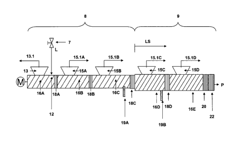
A basic and exemplary embodiment of the process step is shown in Fig. 1, In
step a) a concentrated
Fluid L containing at least one non-volatile polymer and at least one volatile
compound is fed into
a drying unit comprising in flow direction a drying device (8), which is a
first extruder, and a main
extruder (9) whereby in the first extruder the concentrated Fluid L is first
converted to a
superconcentrated fluid LS by removal of volatile compounds through the vent
ports and vapor
lines of the first extruder and then further converted to a product (F) which
is substantially free of
volatile compounds by further removal of volatile compounds through the vent
ports and vapor
lines of the main extruder.
The concentrated fluid (L) is fed into the first extruder at the feeding point
12A at the conveying
section 16A of the first extruder degassing section of the first extruder.
In one embodiment the temperature of the concentrated fluid L fed into the
drying unit is for
example in the range of from 50 C to 200 C, preferably in the range of 100 C
to 170 C.
The concentrated fluid L for example comprises from 10 to 80, preferably from
25 to 70 wt % and
more preferably from 40 to 65 wt.-% of a non-volatile polymer, preferably a
synthetic rubber and
more preferably (halo)butyl rubber and from about 20 to 90, preferably from 30
to 75 wt% and
more preferably from 35 to 60 wt.-% of volatile compounds whereby the
aforementioned
components non-volatile polymer, volatile compounds add up to 90 to 100 wt%,
preferably to 95
to 100 wt% of the total mass of fluid L.
In a preferred embodiment and where the feedstock fluid L comprises water,
fluid L for example
comprises from 10 to 80, preferably from 25 to 70 wt % and more preferably
from 40 to 65 wt.-%
CA 02791615 2012-08-30
WO 2011/117280 PCT/EP2011/054415
- 10 -
of a non-volatile polymer, preferably a synthetic rubber and more preferably
(halo)butyl rubber,
from 5 to 89.5, preferably from 15 to 74.5 wt% and more preferably from 45 to
34.5 wt.-% volatile
organic compounds, in particular a solvent, and 0.5 to 15 wt.-% water, whereby
the
aforementioned components non-volatile polymer, volatile organic compound and
water add up to
90 to 100 wt-%, preferably 95 to 100 wt.-% of the total mass of fluid L.
The concentrated fluid L, while passing through the first drying section 8, in
fig. 1 a first extruder,
undergoes a transition to a superconcentrated fluid LS which is then fed into
the main extruder
section , which is a main extruder in Fig. I.
The superconcentrated fluid (LS) is fed into the main extruder 9 at the
feeding point 12B at the
conveying section 16D of the first extruder degassing section of the main
extruder.
In one embodiment the temperature of the superconcentrated fluid LS fed into
the main extruder is
for example in the range of from 50 C to 200 C, preferably in the range of
80'C to 180 C.
The supereoncentrated fluid (LS) comprises less volatile compounds than the
concentrated fluid L,
The superconcentrated fluid (LS) for example comprises from 50 to 98,
preferably from 60 to 95
wt % and more preferably from 70 to 95 wt.-% of a non-volatile polymer,
preferably a synthetic
rubber and more preferably (halo)butyl rubber and from about 2 to 50,
preferably from 5 to 40
wt% and more preferably from 5 to 30 wt.-% of volatile compounds whereby the
aforementioned
components non-volatile polymer, volatile compounds add up to 95 to 100 wt%,
preferably to 97
to 100 wt% of the total mass of superconcentratedfluid LS.
In a preferred embodiment the superconcentrated fluid LS is preferably free-
flowing as defined
above.
In a preferred embodiment and where the feedstock fluid L comprises water,
superconeentrated
fluid LS for example comprises from 50 to 98, preferably from 60 to 95 wt %
and more preferably
from 70 to 95 wt.-% of a non-volatile polymer, preferably a synthetic rubber
and more preferably
(halo)butyl rubber, from 1,0 to 49,9, preferably from 1,0 to 39,9 wt% and more
preferably from
1,0 to 29,5 wt.-% volatile organic compounds, in particular a solvent, and 0.1
to 10 wt.-%,
preferably 0,1 to 5 wt.-% water, whereby the aforementioned components non-
volatile polymer,
volatile organic compound and water add up to 90 to 100 wt.-%, preferably 95
to 100 wt.-% of the
total mass of superconcentrated fluid LS.
In a typical and exemplary procedure from 10 to 90 wt.-% of the total
volatiles removed in the
drying unit are removed in the first drying section, preferably from 40 to 80
wt.-% and more
preferably from more than 50 to 80 wt.-%.
CA 02791615 2012-08-30
WO 2011/117280 PCT/EP2011/054415
- 11 -
In one embodiment the pressure of the concentrated fluid L fed into the main
extruder is for
example in the range of from 100 klpa to 2 MPa, preferably in the range of
from 500 kPa to 2 MPa.
The pressures and temperatures of the fluids L and LS are typically selected
such that upon
entering the first drying section or the main extruder a significant pressure
drop occurs which
flashes out significant portions of the volatile compounds. Associated
therewith is a significant
temperature drop due to the evaporation of volatile compounds. Typically the
temperature profile
within the first and main extruder is such that the temperature is rising from
one conveying section
to the next.
Suitable extruder types for the main extruder include single screw and
multiscrew extruders
.. comprising any number of barrels and types of screw elements and other
single or multishaft
kneaders Possible embodiments of multiscrew extruders are twin-screw
extruders, ring extruders
or planetary roller extruders, whereby twin-screw extruders and ring extruders
are preferred.
Single screw extruders include those having an axial oscillating screw. Twin
screw extruders are
for example counter-rotating intermeshing, counter-rotating non-intermeshing,
co-rotating
intermeshing and co-rotating non-intermeshing twin screw extruders, whereby co-
rotating
intermeshing twin screw extruders are preferred.
In one embodiment of the invention the extruders can either be heated via the
barrels to
temperatures up to 300 C or cooled.
In a preferred embodiment, the extruder comprises means to operate separate
zones independently
.. of each other at different temperatures so that the zones can either be
heated, unheated or cooled.
In another preferred embodiment the extruder comprises for each conveying
section at least one
separate zone, which can be operated independently at different temperatures.
Preferred extruder materials should be non-corrosive and should substantially
prevent the reheated
concentrated fluid L and the Product P from being contaminated with metal or
metal ions.
Preferred extruder materials include nitrided steel, duplex steel, stainless
steel, nickel-based alloys,
composite materials like sintered metals, hot isostatic pressed materials,
hard wear resistant
materials like Stellite, coated metals with coatings for example made from
ceramics, titanium
nitride, chromium nitride and diamond like carbon (DLC).
The aforementioned extruder types including the heating or cooling means
optionally located in
.. several distinct zones and the materials mentioned for the main extruder
are also suitable for
extruders of a first drying section, whereby any possible combinations of
extruders can be used.
However, in a preferred embodiment the main extruder typically has a larger
cross sectional area
than the first extruder, preferably the ratio of the cross sectional area of
the main extruder A(main)
CA 02791615 2012-08-30
WO 2011/117280 PCT/EP2011/054415
- 12 -
to the cross sectional area of the first extruder A(first) is in the range of
A(main)/A(first) from 1,01
to 5,00, preferably from 1,1 to 3,0 and more preferably from 1,3 to 2,5.
The conveying sections 16B, I6C, 16E and 16F are each open to a vent port (15A
to 15D). The
upstream conveying sections 16A and 16B are open to vent ports 14A and 14B. In
the conveying
sections 16A to 16F a part of the solvent is evaporated and separated from the
reheated
concentrated fluid L. The vapors are removed through the vent ports 14A and
148 and 15A to 15D
via vapor lines 14.1A, 14.1B and 15.IA to 15.1D.
Since the evaporatedvolatile compounds have a tendency to entrain the reheated
concentrated fluid
L or the product P towards the vent ports, in a preferred embodiment of the
invention the vent
ports 15 are designed to prevent the material, in particular the reheated
concentrated fluid L or the
Product P, from coming out of the vent ports.
Suitable means to accomplish that purpose are sniffer srei,vs, that are
mounted on the vent ports
and convey any material back into the extruder, or rollers or belts, that are
applied to the inside of
the vent ports to push deposited material back into the extruder. Stiffer
screws are preferred. The
sniffer screws may comprise one, two or more shafts, whereby stuffer screws
comprising one or
two shafts are preferred.
As an alternative or preferably in addition to the aforementioned, coatings of
the vent ports may be
applied which reduce or prevent sticking of the material to the surface.
Suitable coatings include
DLC, Ethylene-TetrafluoroethyIene (ETFE), Polytetrafluoroethylene (PTFE) and
Nickel-Alloys.
The pressure at the vent ports 14A, I5A and 15B of the first extruder is for
example between 1 hPa
and 2,000 hPa, preferably between 5 hPa and 1500 hPa.
The pressure -at the vent ports 14B, 15C and 1513 of the main extruder is for
example between 1
hPa and 2,000 liPa, preferably between 5 hPa and 1000 hPa.
In a preferred embodiment, the pressure at the vent ports 14B, 15C and 15D of
the main extruder is
lower than at the vent ports 14A, 15A and 15B of the first extruder.
The vapor lines may be and are preferably connected to a condensing system.
In general, the purpose of the condensing system is to collect volatile
compounds removed by the
vent ports via the vapour lines and typically comprises a condenser and a
vacuum pump. Any
condensing system known in the art may be used to effect the recovery of
volatile compounds.
Generally, it is preferred to recycle the condensed volatile compounds,
optionally after carrying
out a phase separation to separate the volatile organic compounds from water,
into a process for
the preparation of fluid L.
CA 02791615 2012-08-30
WO 2011/117280 PCT/EP2011/054415
- 13 -
The conveying sections are terminated by accumulating sections 18A to 18E and
20. The purpose
of the accumulation is to assure a certain pressure level in the vent ports
and to introduce
mechanical energy into the material to facilitate evaporation of volatile
compounds. The
accumulating sections may comprise any means that enable the accumulation of
the material. It
may be designed to include for example kneading or throttling elements,
blister discs or die plates.
Examples of throttling elements are conical or cylindrical flow paths or other
throttling means.
The application of kneading elements, blister discs or die plates within the
accumulating section is
preferred, kneading elements are even more preferred. Examples of kneading
elements include
kneading blocks, which may be designed as double or triple flighted forward,
backward or neutral
conveying kneading blocks; single or double flighted screw mixing elements
with grooves, single
flighted tooth mixing elements, blister plates and single, double or triple
flighted eccentric discs,
The kneading elements may be assembled in any combination on the screw shafts
of the extruder,
in particular of an twin screw counter rotating or co-rotating twin screw
extruder.
A typical accumulating section comprises of 2 to 10 kneading blocks,
oftentimes terminated by a
back conveying type of kneading element. For mixing in of a stripping agent,
tooth type elements
or screw elements with grooves may be applied.
Eccentric discs are preferably applied in the last section of the extruder,
where the product P is
highly viscous and substantially free of volatile compounds
For planetary roller extruders, kneading elements like tooth shaped rollers
are or rollers with
grooves and clearances are preferred.
Generally the main extruder and, as far as the first drying unit is a first
extruder also the first
extruder may comprise one or more conveying sections and one or more
accumulating sections,
whereby the number is only limited by constructional constraints. A typical
number of conveying
sections and accumulating sections is Ito 30, preferably 2 to 20 and more
preferably 3 to 15.
In a preferred embodiment of the invention the reheated concentrated fluid L
or the
superconcentrated fluid LS is injected into the first extruder degassing
section of the first extruder
and the main extruder respectively, whereby the first extruder degassing
section comprises one or
more rear vent ports in upstream direction each connected to a vapor line.
The advantage of rear vent ports is that the volatile compounds present in the
concentrated fluid L
and the superconcentrated fluid LS undergo sudden and rapid evaporation,
thereby effecting at
least partial separation of the polymer and the volatile compounds, the vapors
emerging through
the rear vents in upstream direction. Generally, from about SO to about 99 wt-
%, of the volatile
compounds present in the fluids L and LS are removed through the upstream
vents.
CA 02791615 2012-08-30
WO 2011/117280 PCT/EP2011/054415
- 14 -
The last accumulating section 20 is typically designed to form a product plug
at the outlet of the
extruder, thereby preventing surrounding air from entering the extruder. While
passing from the
conveying sections and the accumulating section to the outlet section 22 the
concentrated fluid L
undergoes a transition from the preferably free-flowing concentrated fluid L
to a superconcentrated
fluid LS in the first extruder and further to the product P in the main
extruder, whereby the product
P typically has a crumbly or plastic-like appearance.
The outlet section 22 typically comprises means to allow the product to exit
the main extruder and
optionally but preferably product processing equipment. Examples of suitable
product processing
equipment includes combinations of die plates and cutters; die plates und
underwater-pelletizing
means; means for crumb formation like screw elements with teeth and holes;
turbulators which
may be designed as cylinders with holes in it, whereby the product is pressed
from the outside to
the inside of the cylinder, and whereby a rotating knife inside the cylinder
cuts the product into
pieces; fixed knifes placed at the end plate of the extruder, whereby the
screw rotation causes the
cutting action, which preferably is applied when working with twin screw co-
rotating, single screw
and planetary roller extruders.
To reduce the mechanical and thermal stress to the product, in a preferred
embodiment of the
invention the product processing equipment is combined with cooling means.
The cooling means comprises any means that allow the removal of heat from the
product.
Examples of cooling means include pneumatic crumb conveyers with convective
air cooling,
vibrating crumb conveyers with convective air cooling, vibrating crumb
conveyer with cooled
contact surfaces, bell conveyer with convective air cooling, belt conveyer
with cooled belts, water
spraying on hot crumbs upon outlet of the extruder and as already mentioned
underwater-
pelletizing means, whereby water serves as the coolant.
The product P may then be processed further for final packing and shipping.
(Halo)butyl rubber for
example is cooled to a temperature of or below 60 C, formed into bales e.g. by
a hydraulic press,
and then packed into boxes or crates for shipment.
In general, an increasing feed rate of the concentrated fluid L at the feeding
point 12A or an
increasing feed rate of the superconeentrated fluid LS at the feeding point
12B requires a
corresponding increase in the screw speed of the first extruder. Moreover, the
screw speed
determines the residence time of fluid L. Thus, the screw speed, feed rate and
the extruder
diameter are typically interdependent. Typically the first extruder is
operated in such a manner that
the dimensionless throughput V/(n*c13), wherein V denotes the Volume flow rate
at the outlet of
the respective extruder or stage, n the screw speed expressed in revolutions
per minute and cl the
CA 02791615 2012-08-30
WO 2011/117280 PCT/EP2011/054415
- 15 -
effective diameter of the extruder is adjusted to about 0.01 to about 0.2
preferably to about 0.015
to about 0,1.
Typically the main extruder is operated in such a manner that the
dimensionless throughput
V/(n*d3) is adjusted to about 0.01 to about 0.7 preferably to about 0.015 to
about 0,5.
.. The maximum and minimum feed rates and extruder screw speeds are determined
by for example
the size of the extruder, the physical properties of the synthetic rubber
product contained in fluids
L and LS and the target values of remaining volatile compounds. Given these
properties, however,
the operating parameters can be determined by one skilled in the art by some
initial experiments.
In one embodiment of the invention the drying unit is operated at a feed rate
of 5 to 25,000,
preferably of 5 to 6,000 kilograms per hour.
The scope of the invention also encompasses embodiments wherein the
superconcentrated fluid LS
leaving the first drying section is fed into two or more main extruder
sections or wherein the
superconcentrated fluid LS leaving two or more first drying sections is fed
into one main extruder
section or any other embodiment wherein the number of first drying sections is
different from the
number of main extruder sections.
Generally, the degassing in the extruders may be aided by the addition of a
stripping agent that is
removed together with other volatile compounds. Even though the stripping
agent may be added
anywhere in the extruder unit, the addition in one or more accumulating
sections is preferred. In a
more preferred embodiment a stripping agent is added in one or more
accumulating sections except
the last one 20.
Suitable stripping agents are substances that are inert to the concentrated
fluid L, the
superconcentrated fluid LS and/or the product P and have a vapor pressure
greater than 100 hPa at
100 C.
In the context of the invention, the term "inert" means that the stripping
agent does not or virtually
not react with the polymers contained in the reheated concentrated fluid L,
the superconcentrated
fluid LS and/or the product P. Suitable stripping agents are nitrogen, carbon
dioxide, noble gases,
propane, butane, water or a mixture of the aforementioned substances, whereby
carbon dioxide is
preferred. The amount of stripping agent may be 0.0001 to 10, preferably 0.001
to 5 and more
preferably 0.1 to 2 wt-% based on the amount of the polymer product obtained
at the outlet section.
The first drying section and the main extruder section need to be connected if
they represent
different devices. Suitable means for connection are tubings, lines, pumps or
conveyor screws or
directly connected barrel sections of the extruder, whereby tubings and lines
are preferably
CA 02791615 2012-08-30
WO 2011/117280 PCT/EP2011/054415
- 16 -
equipped with pressure regulation devices such as pressure retention valves or
other means
fulfilling the purpose of keeping the pressure in a desired range.
Fig. 3 shows the same dyring unit as Fig. 1 with the only difference being
that the tubing 23 is
equipped with a gear pump 5 instead of a pressure regulation device 7.
The invention further relates to a device suitable to accomplish the process
according to the
invention. Therefore the invention also encompasses a device comprising a
least
= one first drying section being a kneader or an extruder
= one main extruder comprising at least one feeding point 12, one extruder
degassing section
16, one accumulating section 20 and one outlet section 22, whereby the
extruder degassing
section 16 further comprises at least one vent port 15 connected to a vapour
line 15.1,
whereby the first drying section and the main extruder are in communication.
In the context of this invention the term "in communication" includes direct
or indirect
connections whereby indirect connections may be accomplished for example via
tubes or pipes.
The term "in communication" further includes the option that between the units
or means in
communication further units or means are arranged. In particular the
connections may comprise
pressure regulation devices such as throttles, valves, in particular pressure
retention valves and
pumps such as gear pumps.
The invention further encompasses the use of the aforementioned device for the
production of non-
volatile polymers, which are substantially free of volatile compounds.
The invention further encompasses all devices comprising the specific and non-
specific
embodiments disclosed herein to describe the process as well as a chemical
plant comprising the
aforementioned devices.
Another embodiment of the invention is shown in FIG. 2. FIG. 2 shows another
flow chart and
suitable device for the accomplishment of the process according to the
invention comprising a
kneader as a fist drying section 8 and the same extruder as a main extruder as
already illustrated in
fig. 1. The concentrated fluid L is fed into the kneading section 11 at the
feeding point 10 of the
kneader. The kneading section 11 is open to a vent dome 13. In the kneading
section a part of the
solvent is evaporated and separated from the concentrated fluid L. The vapors
are removed through
the vent dome 13 via vapor line 13.1. The kneading section comprises two
shafts 50A and 50B
each equipped with kneading elements 51. The kneading section in flow-
direction is terminated by
a conveyor screw 52. While passing from the feeding point 10 to the conveying
screw 52 the
concentrated fluid L undergoes a transition from the concentrated fluid L to
the superconcentrated
- 17 -
fluid LS. The conveying screw 52 conveys the superconcentrated fluid LS to the
main extruder 9
via a pressure regulation device 7.
Generally any known type of kneader may be used as a first drying section, as
far as they are
intended or suitable to remove volatile compounds from a concentrated fluid L.
The same applies
to the kneading elements, suitable kneaders are for example disclosed in EP 1
127 609 A and WO
94/04333 A,
However, the use of a first extruder as first drying section is preferred.
In another embodiment the first drying section is a single-screw or twin-screw
extruder and the
main extruder is a single-screw or twin-screw extruder
Fig. 4 shows the same dyring unit as fig 1 with the difference being that the
tubing 23 is equipped
with a gear pump SA instead of a pressure regulation device 7 and that the
outlet section 22
comprises a pump 5B and an underwater processing device W comprising water
bassin 60.
To reduce the mechanical and thermal stress to the product this embodiment
combines product
processing equipment with cooling means.
Typically, suitable underwater processing devices include combinations of a
water basin and die
plates and cutters, turbulators which may be designed as cylinders with holes
in it, whereby the
product is pressed from the outside to the inside of the cylinder, and whereby
a rotating knife
inside the cylinder cuts the product into pieces; fixed knifes placed at the
end plate of the extruder
whereby the screw rotation causes the cutting action. The cutting is either
done directly under
water or close to a water surface where the time for the product from being
cut to being cooled by
water is kept short, preferably below 60 $ preferably below 10 s. This type of
processing and outlet
section is particularly preferable for temperature and/or oxygen sensitive
polymers such as
halogenated rubbers and in particular bromobutyl rubbers.
In a preferred embodiment of the invention the water temperature is kept in a
range of from above
0 to 60 C, preferably from 10 to 50 C.
For polymers that tend to stick together once cut into pieces it is preferred
that the water basin 60
is filled with water comprising non-sticky compounds, in particular surface-
active compounds.
Suitable compounds and means to accomplish this purpose are disclosed in EP
410 914 A.
Another embodiment is shown in FIG. 5. FIG. 5 shows a single extruder
comprising a first drying
section 8 and main extruder section 9, whereby the different sections have
different MISS sectional
areas. The cross sectional area of the first drying section 8, which comprises
the conveying
sections 16A, 16B and 16C, which are terminated by the accumulating sections
18A, 18B and 18B
CA 2791615 2019-04-01
CA 02791615 2012-08-30
WO 2011/117280 PCT/EP2011/054415
- 18 -
and which are open to vent ports 13.1, 15.1A and 15.1 B is smaller than the
cross sectional area of
the main extruder section 9, which comprises the conveying sections 16D and
16E, which are
terminated by the accumulating sections I8D and 20 and the outlet section 22.
Typically the ratio of the cross sectional area of the first drying section
A(fds) and the cross
sectional area of the main extruder section A(mes) is in the range of from
A(fds)/ A(mes) 0.2 to
0.99, preferably from 0.33 to 0.95 and more preferably from 0.4 to 0.9.
Due to the different cross sectional areas of the conveying sections of the
first drying section and
the main extruder section the volume reduction due to the discharged volatile
compounds can be
considered during the extruding process. The conveying sections 16A , 16B and
16C may
comprise conveying means specifically adapted to the different cross sectional
areas of the
conveying sections 16D and 16E. The different conveying means of the different
conveying
sections may also be operated by different motors. The operating parameters of
the conveying
means of the different conveying sections can be adjusted with respect to each
other for providing
and/or controlling a predefined pressure within each conveying section.
In another embodiment the first drying unit may comprise two or more shafts of
which only one is
part of the main extruder section or vice versa. A typical example thereof are
planetary roller or
ring extruders extruders which form the first drying section whereby only the
main shaft or one
shaft is part of the main extruder section or vice versa. Another example is a
twin-screw extruder
which form the first drying section whereby only one shaft is part of the main
extruder section or
vice versa.
Generally, the any extruder i.e. either a first extruder the main extruder or
both, may comprise one
or more side feeders 19, which may positioned anywhere in the extruder,
preferably in close
proximity to the feeding point or the outlet section 22, Side feeders are
suitable for the addition of
additives to the polymer. In fig. 5 one side feeder WA is located in the first
drying section and
another side feeder 1913 in the main extruder section.
Examples of additives, in particular for (halo)butyl rubber products include
stabilizing agents, acid
scavengers like ESE (epoxidized soy bean oil), stearates like calcium
stearates, antioxidants and
the like. Examples of suitable antioxidants include sterically hindered
phenols like
butylhydroxytoluenes and its derivatives like Inganox 1010 and 1076, amines,
mercapto-
benzirnidazoles, certain phosphites and the like.
In particular, (halo)butyl rubbers are mixed with additives, e.g. 0.0001 to 4
phr epoxidized soy
bean oil (ESB0), 0.0001 to 5 phr calcium-stearate and 0.0001 to 0.5 phr of
antioxidants (phr =
parts per hundred rubber with respect to rubber weight). Other additives are
also applicable,
dependent on the application of the butyl rubber product, i.e. fillers or
colorants.
CA 02791615 2012-08-30
WO 2011/117280 PCT/EP2011/054415
- 19 -
As an alternative or in addition to that, additives may also already be added,
as far as they are
liquid together with the stripping agent.
In a preferred embodiment of the invention the concentration unit, the
reheating unit or the
extruder unit may independently of each other be equipped with one or more
pressure regulation
devices which allow the very precise operation of the units under predefined
conditions.
The pressure regulation devices may be active or passive, whereby active
pressure regulation
devices are preferred. Examples of active pressure regulation devices include
control valves like a
pressure relief valve, examples of passive pressure regulation devices include
nozzles and dies or
orifice plates. Suitable valves may be selected from ball, piston, gate or
needle valves.
In case of a passive pressure control device, it is preferred to calculate an
orifice to cause a certain
pressure drop. The calculation is based on viscosity of the fluid at that
point and the throughput.
Anyone skilled in the art can perform this calculation.
Active pressure control devices are typically controlled by a pressure
measurement upstream of the
device. The pressure is for example measured and compared to the set point.
The pressure control
device is then adjusted according to the offset recognized.
Alternatively the pressure drop across the device is measured instead of the
absolute pressure
upstream of the pressure control device. The valve position is adjusted
manually, electrically,
pneumatically or hydraulically. The control of the valve position, i.e.
adjustment to the set point
pressure, can for example be made manually or from any automated process
control system.
In Fig. 5 a pressure regulation device 7 is located before the feeding point
12 of the drying unit.
It was found that a significant reduction of volatile compounds or water or
both can be achieved in
an advantageous way by preparing the fluid L in a process comprising at least
the steps of
A) treating a fluid in at least one concentrator unit comprising at least a
heater, a degassing
vessel and a vapor line , whereby the fluid is heated, the heated fluid is fed
into a
degassing vessel where part of the volatile compounds are removed via the
vapor line to
obtain a concentrated fluid,
B) reheating the concentrated fluid from step A) in at least one reheating
unit to obtain a
concentrated fluid L;
A basic and exemplary embodiment of the process steps A) and B) is shown in
Fig. 6. In step A)
Fluid F containing at least one non-volatile polymer and at least one volatile
compound is
transferred via pump 1 to the heater 2, where the fluid F is heated.
CA 02791615 2012-08-30
WO 2011/117280 PCT/EP2011/054415
- 20 -
Fluid F, also called cement, may contain for example from 3 to 50 wt % of a
non-volatile polymer,
preferably a synthetic rubber and more preferably a (halo)butyl rubber and
from 60 to 97 wt%
volatile compounds, in particular a solvent or a solvent and water, whereby
the aforementioned
components add up to 90 to 100, preferably 95 to 100 wt% of the total mass of
fluid F.
The solvent is preferably selected from the group consisting of linear or
branched alkanes having
between 4 and 10 C atoms, preferably 4 to 7 C atoms. More preferred solvents
are n-pentane, iso-
pentane, n-hexane, cyclo-hexane, iso-hexane, methyl-cyclopentane, methyl-
cyclohexane and n-
heptane as well as mixtures comprising or consisting of those alkanes.
In a preferred embodiment of the invention, fluid F contains from 3 to 40 wt %
of a non-volatile
polymer, preferably a synthetic rubber and more preferably (halo)butyl rubber,
from 60 to 95 wt%
volatile organic compounds, in particular a solvent, and from 0.5 to 20 wt%
water, whereby the
aforementioned components add up to 95 to 100 wt% of the total mass of fluid
F.
The fluid F is typically obtained from polymerization processes or subsequent
processing steps. A
subsequent processing step is for example the halogenation of butyl rubber.
Fluids F containing
water are typically obtained after steam stripping processes following the
polymerization.
The fluid F entering the heater typically and preferably has a temperature of
10 C to 100 C,
preferably of 30 C to 80 C. The viscosity of fluid F is for example in the
range of 100 mPa*s to
25,000 InPa*s, preferably in the range of 500 mPes to 5,000 mPes,
A heater may be any device that is able to raise the temperature of Fluid F.
In a preferred
.. embodiment, heater 2 is a heat exchanger, They heating medium is selected
from the group
consisting of steam, heating oil or hot pressurized water. The heat exchanger
is for example of
shell-and-tube type, where the fluid F is inside the tubes and the heating
medium is on the shell
side. Special inserts in the tubes may be applied to enhance heat transfer.
Another type of heat
exchanger may also be used, in which fluid F is on the outside of the heat
exchanger tubes. The
.. advantage of the aforementioned types of heat exchangers is the avoidance
of maklistribution and
easy maintenance as well as good heat transfer. Said heat exchangers are well
known and
commercially available. In a less preferred embodiment Plate type heat
exchangers may also be
applied.
Upon heating, heated fluid G is obtained. The heated fluid G has a higher
temperature than fluid F,
preferably a temperature of 100 to 200 C, more preferably 110 C to 190 C and
even more
preferably 120 C to 175 C, The heated fluid G is then conveyed further into a
degassing vessel 4.
In the degassing vessel, the volatile compounds at least partially evaporate.
Generally the degassing vessel may be a flash evaporator or another device
typically used to
remove volatile compounds while simultaneously having short retention times.
CA 02791615 2012-08-30
WO 2011/117280 PCT/EP2011/054415
- 21 -
The vapors are separated and removed from the heated fluid G by a vacuum line
4.1. The pressure
in the degassing vessel 4 is for example in the range of 100 hPa to 4,000 hPa,
preferably in the
range of 200 hPa and 2,000 hPa and more preferred in the range of 230 to 1,100
hPa.
The vapors removed via the vacuum line 4.1 are preferably condensed and
recycled into the
process for preparation of fluid F. After degassing and separation a
concentrated fluid H is
obtained, which is removed from the degassing vessel 4 by means of a pump 4.2.
In a preferred embodiment of the invention the degassing vessel is designed in
the shape of a
cyclone to further aid separation of vapor from heated fluid G. In another
preferred embodiment of
the invention the degassing vessel 4 has a conical or at least torisperical
shaped bottom, to allow
the vessel being emptied completely or substantially complete.
In another embodiment the inner surface of the degassing vessel can be heated.
The pump 4.2 is preferably directly connected to the outlet of the degassing
vessel 4. In general,
the connection piece between pump and vessel is preferably as short as
possible.
The pump 4.2 may be selected from the group consisting of positive
displacement type pumps,
gear pumps, piston pumps, membrane pumps, screw type pumps, extruder type
pumps like
counter-rotating or co-rotating single or twin screw extruders or kneader type
pumps. Positive
displacement type pumps and gear pumps are preferred, gear pumps are even more
preferred.
In another preferred embodiment the pump 4.2 comprises a combination of an
extruder or a
kneader and a gear pump whereby the gear pump is fed from the extruder or
kneader.
The amount of volatile compounds that is removed in this step A) is for
example dependent on the
temperature of fluid G and the pressure in the degassing vessel 4. In a
preferred embodiment of the
invention the temperature of fluid G and the pressure in the degassing vessel
4 are chosen so that
the concentrated fluid H is preferably free-flowing as defined above and
comprises for example
from 10 to 60, preferably from 25 to 60 wt % of a non-volatile polymer,
preferably a synthetic
.. rubber and more preferably (halo)butyl rubber and from about 40 to about
90, preferably from 40
to 75 wt% volatile compounds whereby the aforementioned components non-
volatile polymer,
volatile organic compound and water add up to 90 to 100 wt%, preferably to 95
to 100 wt% of the
total mass of fluid H.
In a preferred embodiment and where the feedstock fluid F comprises water,
fluid 1-1 for example
comprises from 10 to 60, preferably from 25 to 60 wt % of a non-volatile
polymer, preferably a
synthetic rubber and more pieferably (halo)butyl rubber, from about 25 to
about 90, preferably
from 25 to 75 wt% volatile organic compounds, in particular a solvent, and
about 0.5 to about 15
wt% water, whereby the aforementioned components non-volatile polymer,
volatile organic
CA 02791615 2012-08-30
WO 2011/117280 PCT/EP2011/054415
-22 -
compound and water add up to 90 to 100 wt%, preferably 95 to 100 wt% of the
total mass of fluid
H.
The temperature of the concentrated fluid H is lower than that of heated fluid
G and is for example
in the range of 15 to 100 C, preferably in the range of 30 to 100 C. The
pressure of the heated
fluid G is for example in the range of 2 to 60 bar, preferably in the range of
4 to 30 bar. The
concentrated fluid H is preferably free-flowing as defined above.
In step B), the concentrated fluid H obtained in step A) is then passed
through a reheating unit 6 to
obtain a concentrated fluid L. The a preferred embodiment the reheating unit
comprises a heat
exchanger, whereby the same disclosure including the preferences with regard
to heating media
and heat exchanger types apply as described above for heat exchanger 2.
The temperature of the reheated concentrated fluid L is typically higher than
that of the
concentrated fluid L and is for example in the range of 50 C to 200 C,
preferably in the range of
90 C to 180 C. The pressure of the heated fluid G is for example in the range
of 2 to 60 bar,
preferably in the range of 4 to 30 bar. The concentrated fluid L is preferably
free-flowing as
defined above.
The heating stream of the heating unit 6 may be used after heating the
concentrated fluid H for
heating the fluid F in the heater 2. The heating stream of the reheating unit
6 may be in
communication with the heater 2. In addition or in alternate the heating
stream leaving the heating
unit 6 and/or the heating stream entering the reheating unit 6 may be in
communication with a
further reheating unit 6 and/or a further heater 2 as. Preferably the heating
stream leaving the
reheating unit 6 and/or the heating stream entering the reheating unit 6 may
be in communication
with one or more degassing vessels 4 and/or in communication with one or more
drying units.
Further it is possible that the heating stream leaving the heater 2 and/or the
heating stream entering
the heater 2 may be in communication with one or more degassing vessel 4
and/or in
communication with one or more drying units. Particularly preferred the
heating stream of the
heater 2 and/or of the reheater unit 6 are led in counter flow with respect to
the heated fluids. Due
to a suitable connection of the heating streams of the heater 2, the reheating
unit 6 and if so The
degassing vessel 2 and/or the drying units a large amount of the heat content
of the heating stream
can be used. This leads to an increased energy efficiency with respect to the
required heat flows at
different devices. If necessary, the heating stream may be heated additionally
between two
different devices for controlling a required temperature of the heating
stream. In most cases this
additional heating of the heating stream may take place at lower temperatures
and at a lower
exergy level compared to the environment so that the additional heating of the
heating stream can
be facilitated and enables a better overall efficiency,
CA 02791615 2012-08-30
WO 2011/117280 PCT/EP2011/054415
-23 -
Following steps A) and B) in step a), the concentrated fluid L obtained in
step B) is passed on to a
drying unit and fed into the conveying section I6A of a first extruder at the
feeding point 12A,
whereby the first extruder represents the first drying section 8 of the drying
unit. The conveying
sections 16A, 16B, 16C and 16D are open to vent ports 14A, 15A, 15B and 15C.
In the conveying
sections a part of the solvent is evaporated and separated from the
concentrated fluid L. The vapors
are removed through the vent port via vapor lines 14.1, 15.1A, 15.113 and
15.1C. While passing
from the conveying section 16A to the accumulating section 18D the
concentrated fluid L
undergoes a transition from the concentrated fluid L to the superconcentrated
fluid LS. The
superconcentrated fluid LS, after passing the gear pump 5 and tubing 23, then
is fed into the
conveying section 16E of the main extruder at the feeding point 12B. The
conveying sections 16E,
16F, 16G and 16H are open to vent ports 14B, 15D, 15E and 15F. In the
conveying sections a
further part of the solvent is evaporated and separated from the
superconcentrated fluid LS. The
vapors are removed through the vent port via vapor lines 14.1B, 15.1D, 15.1E
and 15.1F. While
passing from the conveying section 16E to the accumulating section 20 and the
outlet section 22
the superconcentrated fluid LS undergoes a transition to the product P, which
is substantially free
of volatile compounds.
It was further found that a significant reduction of remaining hydrophilic
compounds or water or
both can be achieved in an advantageous way by preparing the fluids F or L in
a process of
removing hydrophilic compounds and optionally water from a crude fluid A
containing at least one
non-volatile polymer, at least one volatile organic compound, one or more
hydrophilic compounds
and optionally water which comprises at least the step of
pre A) treating the crude fluid (A) in at least one pre-washing unit
comprising at least a separating
apparatus (26), whereby the fluid (A) is mixed with water to obtain an organic
phase (28)
comprising primarily non-volatile polymer and volatile organic compounds and
an aqueous
phase (27) comprising primarily water and hydrophilic compounds, and whereby
the
organic phase (28) is separated from the aqueous phase (27) in a separating
apparatus (26)
and further used as fluid (F) or directly as concentrated fluid L and whereby
at least a part
of the aqueous phase (27) is removed from the separating apparatus (fluid C),
In the context of this invention the term "hydrophilic compounds" denotes at
least partially water-
soluble volatile and non-volatile compounds. Examples include inorganic salts
and in particular
residues of catalysts employed for the polymerization reaction like e.g.
aluminum salts, iron or
other transition metal salts or halides resulting from halogenation reactions
and neutralizations.
Exemplary embodiments of step pre-A) are illustrated using figures 7, 8, 9 and
10.
CA 02791615 2012-08-30
WO 2011/117280 PCT/EP2011/054415
- 24 -
A very basic and exemplary embodiment of the pre-washing step is shown in
Figs. 8. In step pre-
A) crude fluid A containing at least one non-volatile polymer, at least one
volatile compound and
at least one hydrophilic compound is fed to the mixing section 30 of the
separating apparatus 26,
which is equipped with a mixer 32 and passes through the separating wall 34
into a settling
section, where the mixture separates into an aqueous phase 27 and an organic
phase 28, whereby
the separation is supported by means of a coalescer 29. A part of the aqueous
phase 27 is removed
from the separating apparatus 26 as fluid C, which is typically disposed of,
with the rest being
enriched with fresh water E and recycled via the recirculation line 38 by the
action of recirculation
pump 36 back into the mixing section 30. The organic phase 28 is removed and
subjected to the
subsequent process according to steps a) to e) as fluid F.
Generally, the coalescer in the pre-washing step is beneficial, but not
mandatory. It helps to collect
and coalesce the droplets and guides them to the phase interface which
typically results in shorter
residence times Suitable examples of coalescers include structured or
unstructured packings.
Structured packings are for example flat plates, flat vanes, roof-shaped vanes
and vanes with holes
in vertical direction. The vanes or plates may be positioned rectangular or
parallel to the main flow
direction or with a slope. Unstructured packings are for example wire mesh,
packings made of
rings, spheres, cylinders, irregularly shaped geometries and weirs like
distributor plates that have
holes or slits, vertical plates covering a portion of the main flow path. The
pack ings can be made
of any technically feasible material, e,g, metals, glass, ceramic, coated
metals, tined metals and
polymeric materials like for example PTFE, ETFE, polyethylene (PE),
polyetheretherketone
(PEEK), Polypropylene (PP), polyamide (PA) and polyvinylidenflttoride (PVDF).
In a preferred embodiment of the invention step pre-A) is repeated at least
once, preferably once.
A further improved and preferred embodiment of the pre-washing step is shown
in Fig. 9. In step
pre-A) of this double-stage prewashing step fluid A containing at least one
non-volatile polymer, at
least one volatile compound and at least one hydrophilic compound is fed to
the mixing section
30A of a first separating apparatus 26A, which is equipped with a mixer 32A
and passes through
the separating wall 34A into a settling section, where the mixture separates
into an aqueous phase
27A and an organic phase 28A, whereby the separation is supported by means of
a coalescer 29A.
A part of the aqueous phase 27A is removed from the separating apparatus 26A
as fluid C, which
is typically disposed of, with the rest being recycled via the recirculation
line 38A by the action of
recirculation pump 36A back into the mixing section 30A, The organic phase 28A
is removed and
fed as fluid B to the mixing section 30B of a second separating apparatus 26B,
which is also
equipped with a mixer 32B and passes through the separating wall 34B into a
settling section,
where the mixture separates into an aqueous phase 27B and an organic phase
28B, whereby the
separation is supported by means of a coaleseer 29B. A part of the aqueous
phase 27B is recycled
CA 02791615 2012-08-30
WO 2011/117280 PCT/EP2011/054415
-25 -
to the mixing section 30A of the first separating apparatus 26A as fluid D by
the action of
recirculation pump 40 and recirculation line 42, with the rest being enriched
with fresh water E
and recycled via the recirculation line 38B by the action of recirculation
pump 368 back into the
mixing section 30B of the second separating apparatus 26B. The organic phase
28 leaving the
second separating apparatus 26B is subjected to the subsequent process
according to steps a) to c)
as fluid F. An advantage of this double-stage pre-washing step is that fluid F
is substantially free of
hydrophilic compounds and the amount of waste water is reduced due to
recycling which results in
higher concentration of hydrophilic compounds in fluid C.
In a preferred embodiment of the invention the separation is performed at
temperatures of more
than 40 C. The upper limit depends on the constitution of the polymer and the
construction of the
separating apparatus. Typically the upper limit is 125 C,
In a more preferred embodiment of the invention the separation is performed at
temperatures of 40
to 110 C preferably at temperatures of 80 to 110 .
Depending on the composition of fluid A and the boiling points of the
components thereof, the
separating apparatus may be designed to be operated under pressure.
Generally, the efficiency of the pre-washing step increases with increased
temperature.
In another embodiment of the invention the organic phase 28 leaving the
separating apparatus may
be pre-heated to facilitate the free-flow of fluid F. This purpose can also be
accomplished by a
heater, whereby heat exchangers as disclosed for heater 2 above are preferred.
A further improved and preferred embodiment having additional heaters for
fluid A and fluid F is
shown in Fig. 10 which is apart form the heaters identical to Fig. 9. Fluid A
is heated before
entering the separating apparatus by heater 25, the organic phase 28 leaving
the second separating
apparatus 26B is heated by heater 44.
The performance of Step pre-A) is particularly advantageous for fluids F or L
containing halobutyl
rubbers, and in particular for chlorobutyl and bromobutyl rubbers, since crude
halobutyl rubber
solutions often contain high amounts of inorganic halides resulting from the
halogenation of the
polymer.
For example, a fluid A stemming from the bromination of butyl rubber typically
contains inorganic
bromide levels of 3,000 to 5,000 ppm calculated on the mass of bromobutyl
rubber, Upon
performance of step pre-a) this level can be reduced to less than 500ppm,
preferably to less than
300ppm and even more preferably to less than 100 ppm..
For example, a fluid A stemming from the chlorination of butyl rubber
typically contains inorganic
chloride levels of 1,000 to 5,000 ppm ealeulated on the mass of ehlorobutyl
rubber. Upon
CA 02791615 2012-08-30
WO 2011/117280 PCT/EP2011/054415
-26 -
performance of step pre-a) this level can be reduced to less than 500ppm,
preferably to less than
300ppm and even more preferably to less than 100 ppm.
It was further found that the performance of step pre-A) allows to
significantly reduce the water
content of fluid F or fluid L compared to fluid A, which contributes to a
significantly lower energy
consumption for the subsequent steps.
One further embodiment of the invention is shown in FIG. 7. Fn, 7 shows a
basic flow chart and
suitable device for the accomplishment of the process comprising the steps pre-
A),A), B) and a).
In step pre-a) fluid A containing at least one non-volatile polymer, at least
one volatile compound
and at least one hydrophilic compound is fed to the mixing section 30 of the
separating apparatus
26, which is equipped with a mixer 32 and passes through the separating wall
34 into a settling
section, where the mixture separates into an aqueous phase 27 and an organic
phase 28, whereby
the separation is supported by means of a coaleseer 29. A part of the aqueous
phase 27 is removed
from the separating apparatus 26 as fluid C, which is typically disposed of,
with the rest being
enriched with fresh water E and recycled via the recirculation line 38 by the
action of recirculation
pump 36 back into the mixing section 30. The organic phase 28 is removed as
fluid F, In step A)
Fluid F is transferred via pump 1 to the heater 2, whereby heated fluid G is
obtained. Heated fluid
G is fed into the degassing vessel 4. The vapors emerging from the heated
fluid G are separated
and removed by a vacuum line 4.1. After degassing and separation a
concentrated fluid H is
obtained, which is removed from the degassing vessel 4 by means of a pump 4,2.
In step B), the concentrated fluid H obtained in step A) is then passed
through a reheating unit 6 to
obtain a concentrated fluid L, In step a), the concentrated fluid L obtained
in step B) is passed on
to a drying unit and fed into the conveying section 16A of a first extruder at
the feeding point 12A,
whereby the first extruder represents the first drying section 8 of the drying
unit. The conveying
sections 16A, 16B, 16C and I6D are open to vent ports 14A, I5A, 15B and I5C.
In the conveying
sections a part of the solvent is evaporated and separated from the
concentrated fluid L. The vapors
are removed through the vent port via vapor lines 14.1, 15.1A, 15.1B and
15.1C. While passing
from the conveying section 16A to the accumulating section I8D the
concentrated fluid L
undergoes a transition from the concentrated fluid L to the superconcentrated
fluid LS. The
superconcentrated fluid LS, after passing pressure regulation device 7 and
tubing 23, then is fed
into the conveying section 16E of the main extruder at the feeding point 12B.
The conveying
sections 16E, 16F, 16G and 16H are open to vent ports 14B, 15D, 15E and 15F.
In the conveying
sections a further part of the solvent is evaporated and separated from the
superconcentrated fluid
LS, The vapors are removed through the vent port via vapor lines 14.1B, 15.1D,
15,1E and 15.1F.
While passing from the conveying section 16E to the accumulating section 20
and the outlet
- 27 -
section 22 the superconcentrated fluid LS undergoes a transition to the
product P, which is
substantially free of volatile compounds.
It was further found that fluid A comprsing halogenated butyl rubbers may
obtained with
significantly lower overall energy consumption by a process comprising at
least the steps of
I) providing a reaction medium comprising
= a common aliphatic medium comprising at least 50 wt.-% of one or more
aliphatic
hydrocarbons having a boiling point in the range of 45 C to 80 C at a pressure
of
1013 hPa, and
= a monomer mixture comprising at least one monoolefin monomer, at least
one
multiolefin monomer and either no or at least one other co-polymerizable
monomer in a mass ratio of monomer mixture to common aliphatic medium of
from 40:60 to 95:5, preferably from 50:50 to 85:15 and more preferably from
61:39 to 80:20;
II) polymerizing the monomer mixture within the reaction medium to
form a rubber solution
comprising a rubber polymer which is at least substantially dissolved in the
medium
comprising the common aliphatic medium and residual monomers of the monomer
mixture;
1H) separating residual monomers of the monomer mixture from the
rubber solution to form a
separated rubber solution comprising the rubber polymer and the common
aliphatic
medium,
IV) halogenating the rubber polymer in the separated rubber solution
to obtain fluid A, a
solution comprising the halogenated rubber and the common aliphatic medium,
In one embodiment and where the halogenation in step IV) is performed using a
bromination
agent, the bromination agent may be reoxidized using an oxidizing agend such
as hydrogen
peroxide.
As used herein the term "at least substantially dissolved" means that at least
70 wt.-%, preferably
at least 80 wt.-%, more preferably at least 90 wt.-% and even more preferably
at least 95 wt.-% of
the rubber polymers obtained according to step II) are dissolved in the
medium. Such a process is
known from WO 2010/006983 A.
The invention is in particular advantageous in view of energy and fresh water
consumption. The
products obtained are free of volatile compounds.
CA 2791615 2019-04-01
CA 02791615 2012-08-30
WO 2011/117280 PCT/EP2011/054415
- 28 -
Examples
Analytical methods
Water content of fluids F: The sample was put into a centrifuge and spun for
5ntin at 4000 rpm at
room temperature. The water was then collected at the bottom of the vial and
weighed.
Total volatiles concentration: A rubber sample was out into small pieces of
2x2mm size. Roughly
30g of rubber pieces were put in an alumina crucible. The weight of the
crucible and the rubber
was determined. The crucible including the rubber sample was then placed in a
vacuum oven at a
vacuum level of 130 hPa for 60 min at a temperature of 105 C. After drying,
the crucible was
placed in an exsiccator and let cool down for 30min. The crucible was then
weighed again. The
loss in weight was determined.
Residual solvent concentration in product P: The residual solvent
concentration in the product was
determined by headspace gas chromatography. A weighed portion (0.5 +- 0.005 g)
of sample was
placed in a headspace vial, and a measured amount of solvent (1,2
dichlorobenzene, ODCB) was
added. The vial was sealed and shaken until the rubber was dissolved. The vial
was heated until
the volatile organic compounds were distributed at equilibrium between the
sample and the gas
phase in the vial (headspace). An aliquot of the headspace gas was injected
into a stream of carrier
gas, which carries the sample along a chromatographic column. Standards of
known composition
were used to calibrate the GC, Toluene was added to the solvent for use as an
Internal Standard.
Residual water concentration in product P: The total volatiles concentration
is the sum of water,
solvents and monomers. As the monomer concentration is usually less then
0.0005wt%, the water
content can be determined by subtracting the solvent concentration from the
total volatiles
concentration.
Solvent concentration in fluids: The concentration of solvents in fluids were
measured using gas
chromatography. The internal standard was isooctane. The sample was diluted
with toluene and
then injected into the gas chrornatograph. The gas chromatography was
performed on a HP 6890
chromatograph, with following specifications:
- column type DB-5 of J&W, length 60m, diameter 0.23mm, film thickness 1.01Am
- injector temp.: 250 C
- detector temp.: 350 C
- carrier gas: Helium
- column pressure: 96kPa
- detector: PID
CA 02791615 2012-08-30
WO 2011/117280 PCT/EP2011/054415
- 29 -
Viscosity of fluids: The viscosity was measured in a rotational rheometer of
cone¨plate type. All
given viscosities refer to the extrapolated zero shear viscosity.
Examples 1 to 7; Pre-washing
General Remarks
A crude bromobutyl rubber solution, hereinafter denoted as fluid (A), was
taken from a
commercial bromobutyl rubber production plant. Fluid (A) contained two phases:
an aqueous
phase (56 wt%) and an organic phase (44 wt%). The overall ratio of bromobutyl
rubber with
respect to hexanes in the organic phase alone was constant throughout the
examples, being 22 wt%
bromobutyl rubber and about 78 wt% hexanes. The bromobutyl rubber, contained
in fluid (A) had
the following properties, once finished and dried: Mooney (MI 1+8, 125 C) of
32 4, bound
bromine content 1.8 0.2 wt%.
Fluid (A) further comprised certain additives, the concentration being given
as mass fraction with
respect to the rubber mass (phr = parts per hundred parts of rubber):
ESBO: 1 to 1.6 phr, calcium stharate 1,3 to 1.7 phr, Irganox 0.03 to 0.1 phr
The aqueous phase had a typical pH-value of 9.5, In addition to the additives,
fluid (A) comprised
inorganic components like bromides, chlorides, calcium, sodium, aluminum and
small amounts of
other inorganic components.
The experiments in examples 1 to 7 were carried out using a glass vessel
having a volume of 11.
Experiments were performed batchwise. The vessel was equipped with a stirrer.
The water content in the organic phase was determined as described above.
Example 1
A sample of fluid (A) was placed in the stirred vessel and stirred for 10 min
at 58 C. Then the
stirrer was stopped and the sample was left for settling. After 30 min the
organic phase was
separated from the aqueous phase and the residual water content measured in
the centrifuge. The
residual amount of water was 35 vol%.
Example 2
160 ml of fluid (A) were placed in the vessel and 240 ml of water were added.
The mixture was
stirred for 10 min at 58 C. Then the stirrer was stopped and the mixture was
left for settling. After
30 min the organic phase was separated from the aqueous phase and the residual
water content
measured in the centrifuge. The residual amount of water in the organic phase
was 10.0 vol%.
CA 02791615 2012-08-30
WO 2011/117280 PCT/EP2011/054415
- 30 -
Example 3
160 ml of fluid (A) were placed in the vessel and 240 ml of water were added.
The mixture was
stirred for 10 min at 90 C. Then the stirrer was stopped and the mixture was
left for settling. After
30 min the organic phase was separated from the aqueous phase and the residual
water content
measured in the centrifuge. The residual amount of water in the organic phase
was 6.5 vol%.
Example 4
160 ml of fluid (A) were placed in the vessel and 240 ml of water were added.
The mixture was
stirred for 10 min at 105 C. Then the stirrer was stopped and the mixture was
left for settling.
After 30 min the organic phase was separated from the aqueous phase and the
residual water
content measured in the centrifuge. The residual amount of water in the
organic phase was 1.5
voi%.
Example 5
A sample of fluid (A) was taken and left settling. The aqueous phase and the
organic phase were
analyzed. The aqueous phase contained 4940mg/1 of inorganic bromides. The
organic phase
contained 20 wt% bromobutyl rubber, 68 wt% hexane and 12 wt% water. The total
inorganic
bromine concentration in the organic phase was 0.15 wt% (1500 ppm).
Example 6
100 ml of the organic phase obtained in example 5 was placed in the stirred
vessel described
above. 40 ml of water added. The resulting mixture was stirred for 15rnin at
ambient temperature
and then left settling for 30 min. The resulting aqueous phase Contained
2280mg/I of inorganic
bromides. The organic phase contained a total of 0.04 wt% (400ppm) of
inorganic bromides.
Example 7
100 ml of the organic phase obtained in example 5 was placed in the stirred
vessel described
above, 80 ml of water added. The resulting mixture was stirred for 15min at
ambient temperature
and then left settling for 30 min. The resulting aqueous phase contained 1100
mg/1 of inorganic
bromides. The organic phase contained a total of 0.025 wt% (250pprn) of
inorganic bromides.
CA 02791615 2012-08-30
WO 2011/117280 PCT/EP2011/054415
-31 -
Examples 8 to 27: Concentration and direct evaporation
The fluid (F) containing butyl rubber used as a feedstock for examples 7 to 28
was obtained from
two different sources:
Preparation of fluid Fl
A crude butyl rubber solution was taken from a commercial production plant,
allowed to settle
several hours and the organic phase separated from the bulk aqueous phase. The
organic phase was
then used to perform the experiments as fluid (F1). Fluid (F1) contained 20
wt% rubber, 70 wt%
hexanes and 10 wt% water calculated on 100 wt% of these three components. The
concentration of
additives with respect to the bramobutyl rubber fraction was:
ESBO: 1 to 1.6 phr, Calcium stearate: 1.3 to 1.7 phr and Irganox: 0.03 to 0.1
phr
The bromobutyl rubber, dissolved in the fluid (F1), had the following
properties, once finished and
dried: Mooney (ML 1+8, 125 C) of 28 to 36, Bound bromine content of 1.6 to 2.0
wt%.
The viscosity of Fluid Fl at 60 C was 1,760mPes
Preparation of fluid F2
Commercially available bromoinityl rubber with a Mooney (ML 1+8, 125 C) of 28
to 16, a
bromine content of 1.6 to 2.0 wt% and an organic volatile concentration of
<0.7 wt% was
dissolved in technical hexane whereby a fluid(F2) was obtained containing 20
wt% rubber, 79
wt% hexanes and 1 wt% water calculated on 100 wt% of these three components
The
concentration of additives with respect to the bromobutyl rubber fraction was:
ESBO: 1 to 1.6 phr, Calcium stearate 1.3 to 1.7phr and Irganox: 0.03 to 0.1
phr
Examples 8 to 12: Concentration
The concentrator unit
The concentrator unit used for the examples was similar to the one shown in
Fig. 6. A piston pump
was used to pump the fluid Fl, which was prepared as described above, to
heater (2). The heater
(2) was a single tube-in-tube type heat exchanger. The internal pipe was
equipped with a static
mixer of Kenics type, the diameter of the internal pipe was 15 mm. The tube
was heated by a tube
shaped shell. The heating medium was heating oil (Marlotherm). A pressure
relief valve (3) was
installed prior to the degassing vessel (4), the pressure upstream of the
valve was controlled
automatically to a set point value. This set point was chosen so that boiling
in the heated fluid (G1)
was prevented. The heated fluid (G) was introduced into the degassing vessel
(4) from the top. The
conical outlet of the degassing vessel (4) was equipped with a pump (4.2),
which was a
CA 02791615 2012-08-30
WO 2011/117280 PCT/EP2011/054415
- 32 -
combination of an extruder type pump and a gear pump. This combination had the
advantage of
being able to handle high viscosities and to build up high pressures. Samples
were taken from the
concentrated fluid (H) to investigate the concentration and viscosity after
the concentration stage.
Example 8
The heating medium of the heater 2 was set to 125 C, the pressure in the
separating vessel 4 was
atmospheric (1013 hPa). The concentrated fluid H in the bottom of the
separating vessel 4 was a
free flowing foamy liquid, as observed through a sight glass and could be
easily conveyed from the
separating vessel using the extraction pump 4.2 as described above. The
concentrated fluid H had a
hexane concentration of 71 wt% and a viscosity of 4,840mPes measured at 60 C.
Example 9
The feedstock, fluid Fl, and the concentration unit were the same as in
example 8. The heating
medium of the heater 2 was set to 155 C, the pressure in the separating vessel
4 was atmospheric
(1013 hPa). The concentrated fluid H in the bottom of the separating vessel 4
was a free flowing
foamy liquid, as observed through a sight glass and could be easily conveyed
from the separating
vessel using the extraction pump 4.2 as described above. The concentrated
fluid H had a hexane
concentration of 53 wt% and a viscosity of 65,000mPa*s measured at 60 C.
Example 10
The feedstock, fluid Fl, and the concentration unit were the same as in
example 8, The heating
medium of the heater 2 was set to 170 C, the pressure in the separating vessel
4 was atmospheric
(1013 hPa). The concentrated fluid H in the bottom of the separating vessel 4
was a free flowing
foamy liquid, as observed through a sight glass and could be conveyed from the
separating vessel
without plugging or product buildup using the extraction pump 4,2 as described
above. The
concentrated fluid H had a hexane concentration of 42 wt% and a viscosity of
317,700 mPa*s
measured at 60 C.
Example 11
The feedstock, fluid FL, and the concentration unit were the same as in
example 8. The heating
medium of the heater 2 was set to 170 C, the pressure in the separating vessel
4 was 500 hPa. The
concentrated fluid H in the bottom of the separating vessel 4 was a free
flowing foamy liquid, as
observed through a sight glass and could be conveyed from the separating
vessel using the
CA 02791615 2012-08-30
WO 2011/117280
PCT/EP2011/054415
- 33 -
extraction pump 4.2 as described above. Only little product buildup was
observed in the conical
outlet section of the separating vessel 4. The concentrated fluid H had a
hexane concentration of
20 wt% and a viscosity of 7,600,00010es measured at 60 C.
Example 12
The feedstock, fluid Fl, and the concentration unit were the same as in
example 8. The heating
medium of the heater 2 was set to 170 C, the pressure in the separating vessel
4 was 230 hPa. The
concentrated fluid H in the bottom of the separating vessel 4 was a free
flowing foamy liquid, as
observed through a sight glass and could be conveyed from the separating
vessel using the
extraction pump 4.2 as described above. Some product buildup was observed in
the conical outlet
section of the separating vessel 4. The concentrated fluid H had a hexane
concentration of 15 wt%
and a viscosity of 15,600,000mPa*s measured at 60 C.
The results of examples 8 to 12 showing the performance of the concentration
stage are
summarized in table I.
Table 1
Example T [ C] at P [hPa] in Hexane content
Viscosity [mPa*s] at
heater 2* degassing vessel 4 f wt%lof
fluid 14* 60 C of fluid H
8 125 C 1013 71% 4,840
9 155 C 1013 53% 65,000
10 170 C 1013 42% 317,700
11 170 C 500 20% 7,600,000
12 170 C 230 15% 15,600,000
temperature set for the heating medium
CA 02791615 2012-08-30
WO 2011/117280 PCT/EP2011/054415
- 34 -
Example 13. Concentration and Extrusion
The device
The device used for the examples was similar to the one shown in Fig. 6. A
gear pump was used to
pump the fluid F to heater 2. The heater 2 was a shell-and-tube type heat
exchanger. The tubes are
heated internally by steam. The fluid F flows around the tubes guided by vanes
to enhance heat
transfer, fluid and vanes are contained in a tubeHeating was accomplished by
160 C hot steam. A
pressure relief valve 3 was installed prior to the degassing vessel 4, the
pressure upstream of the
valve was controlled automatically to a set point value. This set point was
chosen so that boiling in
.. the heated fluid G was prevented. The heated fluid G was introduced into
the degassing vessel 4
from the top. The conical outlet of the degassing vessel 4 was equipped with a
gear pump.
The concentrated fluid H was then passed through a reheating unit 6, which is
of similar design
than described above: a shell-and-tube type heat exchanger heated by steam,
whereby steam is
inside the tubes and the fluid H flows around the tubes. Heating was
accomplished by 160 C hot
steam. which was a single tube-in-tube type heat exchanger. The internal pipe
diameter was 20rnm,
the internal pipe was equipped with a static mixer of type SM.X. Heating was
accomplished by a
tube shell using a heating oil (Marlotherm) as heating medium.
Thereafter, the concentrated fluid L was fed into the drying -unit consisting
of a first extruder and a
main extruder which are connected via a simple tube with a pressure retention
valve.
The first extruder of the drying unit was a counter-rotating intermeshing twin
screw extruder with
a screw diameter of 57 mm and a screw length of 1000mm.
The main extruder of the drying unit was a co-rotating twin screw extruder
with a screw diameter
of 58 trim and a screw length of 3120mm.
Both extruders further comprised a nozzle as a pressure control device 7, (see
Fig. 5) upstream the
feeding point of the extruder.
The first extruder comprises two degassing sections, whereby the first
degassing section is a
backward degassing section. whereby the feeding point 12 was located at the
first extruder
degassing section, whereby the first extruder degassing section comprised a
conveying section
16A, a rear vent port 14A connected to a vapor line 14.1A in upstream
direction and whereby the
.. extruder unit further comprised one downstream extruder degassing section
each comprising a
conveying section 16B, a vent port 15A, whereby the vent port 15A is connected
to a vapour line
15.1A . and whereby the extruder unit further comprised an outlet section 18C.
The main body of the first extruder could be heated by steam to control the
temperature.
CA 02791615 2012-08-30
WO 2011/117280 PCT/EP2011/054415
- 35 -
The rear vent port I4A was connected to a dry running vacuum pump and a
condenser via a first
vapor line 14.1. The other vapor lines 15.1A were connected downstream to the
same vacuum
pump as vapour line (14.1).
A sight glass was installed in the vent ports (14.1A) and 15.1B to allow the
observation of the
conveying behavior and of the product properties in the conveying section 16C.
The outlet kneading zone 18 was equipped with kneading blocks.
The main extruder comprises six degassing sections, whereby the transfer line
23 is a simple
heated tube. The first degassing section is a backward degassing section,
comprising a conveying
section 16D, a rear vent port 14B connected to a vapor line 14,1B in upstream
direction and
whereby the extruder unit further comprised five downstream extruder degassing
sections each
comprising a conveying section 16E to 161, connected to a vent section 15C to
15G, whereby the
vent ports 15C to 15G are connected to a vapour line 15.1C to 15.1G, and
whereby each of the
conveying sections was terminated by an accumulating section 18D to 18G and
20, and whereby
the extruder unit further comprised an. outlet section 22.
The main extruder consists of 13 barrel sections, which could be heated by
steam.
The rear vent port 14.1B was connected to a dry running vacuum pump and a
condenser via a first
vapor line 14.1B. The vent port 15C was connected to the same vapor fine
14.IB.
Vent port 15D was equipped via a stuffer screw to the vent line 15.1D, that
was connected to vapor
line 14.1B.
The vent ports I5E to 15G were equipped with stuffer screws, the vent lines
15.IE to 15.1G were
all connected and ended at the same two stage dry running vacuum pump and
downstream
condenser.
A sight glass was installed in the vent ports (14B) and I5C to allow the
observation of the
conveying behavior and of the product properties in the conveying sections 16D
and 16E,
The accumulatong sections 18D to 181 were made of back conveying elements,
kneading blocks
and crumb formation elements. Accumulation zones 18E to 181 were designed to
allow the
injection of additives and stripping agent.
The outlet kneading section 20 was equipped with kneading blocks.
The outlet section 22 was equipped with a plate type pressure retention zone.
The product was
formed into crumbs at the outlet of the screw by special screw elements and
the rotating action of
the screws.
CA 02791615 2012-08-30
W02011/117280 PCT/EP2011/054415
_ - 36 -
Example 13
Fluid F contained about 22% of a brominated butyl rubber, <5% water, <2% of
additives (mainly
calcium stearate and ESBO), the remainder was hexane. The fluid F was pumped
at a rate of
190kg/h, pressurized to 13bar, heated to 145 C and flashed into a flash tank 4
at atmospheric
pressure, thereby producing a concentrated fluid H comprising a rubber
concentration of 50% and
a water content of less than 2%. The concentrated fluid H was then pressurized
to 12bar and
heated to 125 C. This heated fluid L was then flashed into the degassing
section 16A of the first
extruder at a pressure of 400mbar. The fluid is then conveyed further through
the extruder through
the second degassing section 16B at the same pressure than section 16A. The
rubber concentration
at the outlet of the first extruder was 80%, water content less than 1%. A the
outlet of the first
extruder the fluid LS had a temperature of 120 C and was pressurized to 25bar.
This
superconcentrated fluid LS was then flashed into the degassing section 16D of
the main extruder.
Degassing sections 16D and 16E and 16F were operated at 100mbar pressure. The
barrel
temperature in the vent section 16D was set to 100 ¨ 120 C by steam heating.
The pressures in the
vent sections 160, 16H and 161 were set to 10mbar.
Nitrogen at a rate of each 0.5kg/hr was injected into accumulation section 18E
and 18F, water
containing about 50% of calcium stearate was injected at a rate of each 1.6kWh
into accumulation
sections 18G and 18H.
The rubber temperature at the outlet of the extruder was 160 C, the volatile
content was less than
02%, the water content was less than 0.1%,
The feed extruder was operated at 250rpm, the main extruder at 80rp.tn, the
rubber throughput was
40kg/h.
CA 02791615 2012-08-30
WO 2011/117280
PCT/EP2011/054415
- 37 -
The reference numerals used hereinbefore are summarized below:
1 pump
2, 2A, 28 heater
3 pressure control device
4, 4A, 4B degassing vessel
4.1, 4.1A, 4.18 vapor line
4.2, 4.2A, 4.28 pump
5, 5A, 5B pump
6 reheating unit
7 pressure control device
8 first drying section
9 main extruder section
10 feeding point (kneader)
11 kneading section
12 feeding point (extruder)
13 vent dome
13.1 vapor line
14 rear vent port (upstream)
14.1 vapor line
15, 15A, 15B, 158, 15C vent port (downstream)
15.1, 15.1A, 15.18, 15.1C vapor line
16, 16A, 16B, 160, 16D conveying section (downstream)
18, 18A, 18B, 18C, 18D accumulating section
19, 19A, 198 side feeder
20 last accumulating section
22 outlet section
23 tubing
CA 02791615 2012-08-30
WO 2011/117280
PCT/EP2011/054415
-38-
25,44 heater
26, 26A, 2613 separating vessel
27, 27A, 27B aqueous phase
28, 28A, 28B organic phase
29, 29A, 29B eoalescer
30, 30A, 30B mixing section
32, 32A, 32B mixer
34, 34A, 34B separating wall
36, 36A, 36B recirculation pump
38, 38A, 3813 recirculation line
40 recirculation pump
42 recirculation line
50A, 50B shaft
51 kneading element
52 conveyor screw
60 water bassin
A crude fluid A
waste water
aqueous phase for recycling
E fresh water
fluid F
heated fluid H
concentrated fluid H
concentrated fluid L
LS superconcentrated fluid L
product
underwater processing device