Note: Descriptions are shown in the official language in which they were submitted.
CA 02791830 2012-10-05
PROXIMITY SESSION MOBILITY EXTENSION
REFERENCE TO RELATED APPLICATIONS
[00011 This disclosure is a continuation-in-part of U.S. Patent Application
Serial No.
13/134,396 titled PROXIMITY SESSION MOBILITY to Trung (Tim) Trinh and Alain
Michaud that was filed on June 6, 2011.
TECHNICAL FIELD
100021 This disclosure generally relates to communications, and more
particularly, to
an extended system and method for seamlessly exchanging and interacting with
multimedia content between devices in proximity on a network.
BACKGROUND
[00031 The proliferation of smart phones and the rising popularity of
tablet-like
devices, with their rich multimedia capabilities, have created demands for
seamless
collaboration between these devices in personal and enterprise networks.
Gradually,
these devices have been introduced into the workplace creating a diversified
mobile
client working environment. Seamless collaboration between these devices
becomes
more difficult especially with the variety of available devices coupled with
the differences
in operating systems, versions, vendors, and models.
[00041 Due to technology limitations and form factor of touch screen mobile
and
tablet devices, innovative approaches have been employed to minimize the
typing
required for interactions between the users and the devices. For example, the
use of
gesturing, speech recognition and drag and drop capabilities, instead of
typing in the
required information, have became a trend. Being able to collaborate and share
information without the need to type in information, such as a destination
address, URL
1
CA 02791830 2012-10-05
or authentication credentials, becomes a necessity rather than a desire for
touch screen
or small form-factor mobile devices.
100051 Information can be shared and exchanged through different methods
such as
File Transfer Protocol (FTP), Hypertext Transfer Protocol (HTTP or HTTPs) (web
session), Virtual Private Network (VPN), Remote Desktop Protocol (RDP), etc.
These
methods require manual authentication or credentials to be exchanged as part
of the
collaborative session initiation. Such requirement makes it impractical for
the touch-
screen devices that are dominantly relied on by drag-and-drop or gesture-based
interactions.
100061 Often, participants brought into a conference call on the spot are
not briefed
of the context of their participation such as the meeting topic or the reason
why that
participant's presence is required. Guest users also need to have a temporary
identification issued or go through a manual device registration process
before gaining
access to enterprise WiFie connectivity unless the enterprise has an open
WiFie
connectivity without security restriction,
[00071 As a further restriction on current systems, mobile users who wish
to transfer
data from their mobile device to a local machine or device at a visiting
enterprise, have
to download data which includes transferring data from their enterprise to the
mobile
device then transfer the data back to the visiting enterprise. This incurs
mobile data
transfer costs using standard 30/4G networks. The participant also needs to
request
WiFie access subject to the approval from the proper department at the
visiting
enterprise. Once approval is given, the participant can enter in a service set
identifier
(SSID), access token and select the proper encryption option, the process
being tedious
and not guaranteeing instant access.
100081 In conferences, the participant often uses an available whiteboard
in the
room. A number of issues arise, however. People in the conference call will
not be
capable of seeing what is being drawn nor can they fully participate. These
outside
participants are not able to interact and provide their own input.
Furthermore, the
content is not easily captured for the future and cannot be referenced for
follow ups.
2
CA 02791830 2012-10-05
[0009] Therefore, an extension to a proximity session mobility system and
method is
needed that facilitates the seamless exchange of media content and interaction
between different devices within a network. These, as well as other related
advantages,
will be described in the present disclosure.
BRIEF DESCRIPTION OF DRAWINGS
[00101 The novel features believed to be characteristic of the disclosure
are set forth
in the appended claims. In the descriptions that follow, like parts are marked
throughout
the specification and drawings with the same numerals, respectively. The
drawing
figures are not necessarily drawn to scale and certain figures can be shown in
exaggerated or generalized form in the interest of clarity and conciseness.
The
disclosure itself, however, as well as a preferred mode of use, further
objectives and
advantages thereof, will be best understood by reference to the following
detailed
description of illustrative embodiments when read in conjunction with the
accompanying
drawings, wherein:
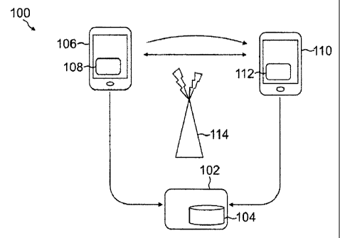
100111 FIGURE 1 is an exemplary system for sharing information between
devices
within proximity in accordance with one or more aspects of the present
disclosure;
100121 FIGURE 2 is a flow chart depicting illustrative procedures for
setting up
devices in accordance with one or more aspects of the present disclosure;
[0013] FIGURE 3 is a flow chart depicting illustrative procedures for
establishing a
communication channel between devices in accordance with one or more aspects
of the
present disclosure;
[0014] FIGURE 4 is a flow chart depicting illustrative procedures for
sharing
information on a user interface provided by an exchange agent module in
accordance
with one or more aspects of the present disclosure;
[0015] FIGURE 5 is an exemplary system for providing a multimedia session
through
a streaming server in accordance with one or more aspects of the present
disclosure;
[0016] FIGURE 6 is a flow chart depicting illustrative procedures for
providing a
3
CA 02791830 2012-10-05
streaming session in accordance with one or more aspects of the present
disclosure;
10017] FIGURE 7 is an exemplary system for providing a reverse lookup to
establish
a communication channel in accordance with one or more aspects of the present
disclosure;
100181 FIGURE 8 is a flow chart depicting illustrative procedures for
setting up the
communication channel using reverse lookup in accordance with one or more
aspects
of the present disclosure;
100191 FIGURE 9 is a sequence diagram depicting illustrative procedures for
seamlessly enabling WiFi communications between a stationary multimedia phone
device and a mobile phone in accordance with one or more aspects of the
present
disclosure; and
100201 FIGURE 10 is a sequence diagram depicting illustrative procedures
for
sharing information from a mobile device to participants in a conference call
in
accordance with one or more aspects of the present disclosure.
DESCRIPTION OF THE DISCLOSURE
100211 The description set forth below in connection with the appended
drawings is
intended as a description of presently preferred embodiments of the disclosure
and is
not intended to represent the only forms in which the present disclosure can
be
constructed and/or utilized. The description sets forth the functions and the
sequence
of steps for constructing and operating the disclosure in connection with the
illustrated
embodiments. It is to be understood, however, that the same or equivalent
functions
and sequences can be accomplished by different embodiments that are also
intended to
be encompassed within the spirit and scope of this disclosure.
[0022] Generally described, the present disclosure relates to
communications. More
specifically, this disclosure relates to proximity session mobility. In one
illustrative
embodiment, a system and method for seamless exchange and interaction of
multimedia content between communication devices in a network are disclosed.
The
4
CA 02791830 2012-10-05
method can include the discovery and identification of devices within
proximity of a
sending device. The found devices can be authenticated through unique
identifiers
established during registration. Connection requirements can be determined
based on
the identifiers associated with the found devices and the sending device. In
turn, the
sender can establish a connection with the found devices using the connection
requirements. The exchanged content can be, but is not limited to, multimedia
based
information, applications, contacts, virtual desktop sessions, remote desktop
sessions
or virtual mobile sessions. The sending device can share or serve as a remote
control
to redirect and navigate the content, with a simple action or a gesture
command, to the
found device. The shared multimedia content, can either reside on the sender's
mobile
device or on a remote server within a connected network. The multimedia
sharing
supports one-to-one and one-to-many topologies.
[00231 As an extension to the system and method, telephony applications can
be
tied in with session mobility. For example, whiteboards on each of the devices
can be
integrated seamlessly. The mobile phone can also act as a remote control to
bring
contacts into the conference call thereby leveraging the mobile phone's native
interface
without the need to know the destination number of the conference device.
Participants
being brought into the conference can be provided with the proper context of
the current
interaction/presentation. Context information can be shown visually or
presented
audibly. In addition, the conferencing appliance can turn into a temporary
WiFit0 access
point or end point for conveniently connecting the user's mobile device to a
corporate
network in a restricted and secured way.
[00241 Numerous advantages can be offered by the illustrative embodiment
described above. Logging into a remote device before sharing or sending
information
has been removed as well as credential exchanges required prior to
collaboration. In
addition, the device can be used as a remote control to redirect the session
and to
navigate the interaction within a new destined session. The proximity sessions
mobility
is not restricted to just sharing of multimedia but potentially can be used to
instantly
transfer information from one small and low end device to a larger and higher
display
quality device for appeal and visual effect enhancements. Bidirectional
collaborative
CA 02791830 2012-10-05
interaction can be achieved with devices that have different makes and models
within a
connected network. The remote device along with white boarding capabilities
can be
used for enhancing conference capabilities. Many additional advantages of the
present
disclosure will become apparent to those skilled in the relevant art as
provided for in the
following description.
100251 Exemplary systems for exchanging content will be described in
FIGURES 1, 6
and 7. FIGURES 2 through 4 will provide exemplary procedures for establishing
a
communication channel between devices. FIGURE 6 discloses procedures for
establishing a streaming session between devices while FIGURE 8 provides
procedures
for a reverse lookup for proper identification of a receiver. FIGURE 9
discloses
procedures for seamlessly enabling a WiFie communication between devices and
FIGURE 10 provides procedures for white boarding from a mobile device to share
information to the participants on the call. In this disclosure, devices can
be referred to
as communication devices that can be mobile or not. These devices can include
tablets, mobile phones, smartphones, personal digital assistants, handheld
computers,
standalone computers, conference devices or the like. The communication
devices can
also be referred to as sending devices and receiving or found devices.
100261 Turning now to FIGURE 1, an exemplary system 100 for sharing
information
between communication devices 106 and 110 within proximity in accordance with
one
or more aspects of the present disclosure is provided. The system 100 can
include an
identity server module 104 operating on a server 102 that can be wirelessly
connected
to a plurality of communication devices 106 and 110 having exchange agent
modules
108 and 112. Communications between them can be facilitated through a wireless
interface 114 distributed within proximity of the devices 106 and 110. Fewer
or more
components can be represented within the system 100 and are not limited to
those
shown. For example, while two devices 106 and 110 have been provided, many
more
can be shown each interconnected with one another through communication
channels
defined by the identity server module 104.
[00271 Proximity session mobility can be applied to any devices 106 and
110. It is
6
CA 02791830 2012-10-05
desirable or often necessary for applications to share data between these
services. The
modules 108 and 112, or at least components thereon, can be used as add-ons to
existing applications or devices 106 and 110. For example, the exchange agent
modules 108 and 112 running thereon can be downloaded onto existing mobile
phones
and or added to conference phones. The wireless interface 114, in association
with the
identity server module 104 on the server 102, can connect components within
the
system 100. Communications between the devices 106 and 110 and to the server
102
can be facilitated through the interface 114. The interface 114 can connect
with the
server 102 wirelessly or through a wireline connection.
100281 Continuing with FIGURE 1, the identity server module 104 can operate
on a
traditional server 102. The server 102 can include an operating system and
software
instructions, memory, at least one processor and a network interface. The
server can
process requests and typically handle high volumes of transactions and large
amount of
queries for communication and data processing. The identity server module 104
can
provide information such as a device's name, number, Internet Protocol (IP)
address
and potentially, location. The module 104 can also provide a mechanism by
which the
devices 106 and 110 can establish a communication channel. The location of the
devices 106 and 110 can be determined by observing one device paired with a
static
device such as a conference phone. The location information can be used to
enhance
the session experience by leveraging what the area has to offer, for example,
local
printers. This information can be used to populate presence information.
[0029] The exchange agent modules 108 and 112 on the communication devices
106 and 110 can be responsible for identifying devices in proximity and
managing the
sharing protocol. Operationally, each of the devices 106 and 110 can maintain
a
wireless interface for communication with one another and the identity server
module
104 on the server 102_ Referring to FIGURE 2, a flow chart depicting
illustrative
procedures for setting up these devices 106 and 110 in accordance with one or
more
aspects of the present disclosure is provided. The procedures can begin at
block 200.
The exchange agent modules 108 and 112 can be downloaded or pre-installed on
each
of the devices 106 and 110. The communication devices 106 and 110 can register
with
7
CA 02791830 2012-10-05
the identity server module 104 which assigns the device a unique device
address or
identifier. These identifiers can be referred to as tokens with usages for
these tokens
becoming apparent from the disclosure provided below. The devices 106 and 110
can
be registered with the module 104 using a number of different techniques.
[00301 Once activated, the exchange agent module 108 on the sending device
106
can scan for devices 110 at block 202. The exchange agent module 108 on the
sending device 106 can scan for nearby devices to identify available receiving
devices
110 within proximity. Numerous types of scanning techniques can be used by the
sending device 106. The scanning techniques can include near field
communications
(NFC), BluetoothT", graphical tag recognition, facial recognition and global
positioning
system (GPS) signaling or wireless networks, depending on the options and the
state
(on/off) of protocols available on the receiving devices 110. A combination of
these
techniques can be implemented and used by the sending device 106.
[00311 Information about receiving devices 110 can be reported back to the
sending
device 106. These found devices 110 can be displayed on a graphical display of
the
sending device 106 along with any other information about the receiving
devices 110 in
proximity with proper user identity which is stored in the identity server
102. For
example, the sending device 106 can locate a number of different devices in
proximity,
but only those that have registered with the identity server module 104 are
shown on
the display of the sending device 106. After scanning is completed, the
exchange agent
module 108 on the sending device 106 now has a unique token for found devices
110.
At block 204, these tokens are retrieved. These unique tokens as described
earlier can
be the information that was provided by the identity server module 104 when
the
devices 110 were registered. These tokens can then be sent to the identity
server
module 104 at block 206. The identity server module 104 can pull up
information or
communicate with all devices 106 and 110 given that the identifiers for them
are known.
The procedures can end at block 208.
100321 In one embodiment, the identity server module 104 can send or push
updates
to known devices 106 and 110 so that they can communicate with each other.
This can
8
CA 02791830 2012-10-05
include auto pairing the BluetoothTM radios on the devices 106 and 110 using
the
identity server module 104 as a mediator. Uniform resource links or IP
addresses for
the communication devices 106 and 110 can be sent to another device.
100331 When the receiving device 110 has been located, communication
between
the sending device 106 and the receiving device 110 can be established and
more
specifically, the exchange agent modules 108 and 112 therein. FIGURE 3 is a
flow
chart depicting illustrative procedures for establishing a communication
channel
between the devices 106 and 110 in accordance with one or more aspects of the
present disclosure. The procedures can begin at block 300. The exchange agent
module 108 on the sending device 106 can use the previously identified
information to
validate the receiving device 110 with the identity server module 104 and
collect more
information for connection requirements.
100341 At decision block 302, the sending device 106 can determine whether
the
receiving device 110 within the previous scan was registered properly. The
receiving
device 110 should have been registered, as guest or known account, with the
identity
server module 104 on the server 102 prior to communicating with the sending
device
106. Within a connected network, it is assumed that all the communication
devices 106
and 110 are already authenticated, and each device is dynamically assigned a
unique
identifier, i.e. an IP address, Media Access Control (MAC) address, electronic
mail
address or phone number so that they can be discovered by other devices.
[00351 When the receiving device 110 has not been registered, the device
110 can
be prompted to register as a guest when the device enters into the system 100
or
detected by the wireless interface 114 at block 304. The identity server
module 104
can also provide a temporary tag which acts as an identifier for the device
110 at block
306. In one embodiment, the assigned tag can be used by other devices, for
example,
via a camera scanning method. The tag can contain an address or a Uniform
Resource
Identifier (URI) referencing the other device. It can also be used to derive
the address
or URI via a reverse lookup. The temporary guest account can also be
established for
the sending device 106 and can be setup through similar methods.
9
CA 02791830 2012-10-05
[0036] At block 308, the identity server module 104 can receive
identification of a
sending device 106 from an incoming query. The identity server module 104 can
know
the identification of both parties through the query. The first identification
can be
obtained from the incoming query which contains the identification such as the
token, IP
address, MAC address etc. of the sending device 106. The identification of the
receiving device 110 can be obtained from the message payload which contains
the
identifier for the receiving device 110 at block 310. With both
identifications known,
the identity server module 104 can initiate a background operation to link
both devices
via a communication channel at block 312. The exchange agent module 108 on the
sending device can then establish the sharing connection with the exchange
agent
module 112 on the receiving device 110. The procedures can end at block 314.
[0037] The channel established between the sending device 106 and the
receiving
device 110 can either be peer-to-peer or client-server based. In one
embodiment, the
communication channel between the devices 106 and 110 is accomplished via a
Transmission Control Protocol (TCP)/User Datagram Protocol (UDP) connection or
Short Message Service (SMS) messaging. The connection can be terminated either
by
the sending device 106 or by a proximity detection mechanism or remotely via
an
administrative interface on the server 102 having the identity server module
104. In one
embodiment, activity on the sending device 106 can be monitored by the
receiving
device 110 or identity server module 104 such that after a period of
inactivity the
session can be closed. Alternatively, the sending device 106 can disconnect
itself after
the period of inactivity.
100381 Content can be provided or shared between the sending device 106 and
receiving device 110. FIGURE 4 is a flow chart depicting illustrative
procedures for
sharing information on a user interface provided by an exchange agent module
108 in
accordance with one or more aspects of the present disclosure. The procedures
can
begin at block 400. With a connection established, a graphical display can
show
depictions of the identified or receiving device 110 so that a user of the
sending device
106 can either drag the application or media to be shared to the receiving
devices 110
or drag the receiving devices 110 to the application or media to be shared at
block 402.
CA 02791830 2012-10-05
Instructions can be provided on the display of the sending device 106.
100391 At decision block 404, the sending device 106 can determine whether
the
user has dragged the device 110 to the application or the application to the
device 110.
The display can provide graphical representations of both. At block 406, when
the
receiving device 110 is dragged to the application, the sending device 106
provides
read only content to the receiving device 110. When the application is dragged
to the
receiving device 110, at block 408, the sending device 106 provides content
which can
be presented as read and write enabled to the receiving device 110. Other
techniques
can be implemented for content sharing. For example, a menu or button click
can
replace the dragging technique. The procedures can end at block 410.
[0040] When receiving static content, the receiving devices 110 can view
and
discard the provided information from the sending device 106. In one
embodiment, the
receiving devices 110 can save the content if the sending device 106 allows it
prior to
starting the shared session. For dynamic content, the receiving device 110 can
edit,
discard or push back the content to the sender or vice versa.
[0041] The proximity session mobility feature can be disabled remotely from
the
server 102 having the identity server module 104 in case of a lost or stolen
device. The
exchange agent modules 108 and 112 on the communication devices 106 and 110,
or
at least a portion thereof, can be implemented as a background service. The
background service can wait for input from either the identity sewer module
104 or
associated/paired devices. This can allow the exchange agent modules 108 and
112 to
be passive and do much if not all of the work with minimal user interaction.
[0042] To illustrate proximity session mobility, an exemplary receiving
device 110, in
the form of a conference phone, and a sending device 106, in the form of a
mobile
phone, is presented. When the mobile phone 106 equipped with an exchange agent
module 108 is pointed at the conference phone 110, also having an exchange
agent
module 112, the conference phone 110 can display a graphical representation of
the
mobile phone 106 in proximity as an identified device that can be shared. The
user can
push a button on the conference phone 110 to confirm and their virtual remote
desktop
11
CA 02791830 2012-10-05
can show up on the conference phone 110. The user of the mobile phone 106 can
either use the conference phone keyboard to navigate the multimedia session or
use
the exchange agent module 108 to control the navigation. To terminate the
sharing
session, the mobile phone user can either initiate a disconnect action from
the
exchange agent module 108 on the mobile phone 106, or just allow out-of-range
proximity detection to be activated by walking away from the conference room
with the
device.
[00431 Once session mobility can be established between a sending device
106 and
a receiving device 110, in the form of a conference appliance, not only can
the user of
the sending device 106 control the presentation on the receiving device 110,
but they
can also initiate a request to bring in their own contacts. For example, the
sending
device 106, from their mobile device's native interface or from a cloud
network access
application such as Google Mae/contact feed, can import in data or contacts
that can
be connected into the conference call without actually making a phone call
from the
sending device 106 to a new user. Furthermore, the sending device 106
typically does
not need to know the conference call number.
[0044] The newly invited user can receive the call alert. In addition, the
user can
receive the context in which the conference call takes place. For example,
caller
information (i.e. the name of mobile device owner instead of the caller id of
the
conference device), meeting participants, meeting topic/subject and the
current
discussion point such as a snap shot of the current presentation, can be
provided to the
newly invited party. Participant information can be presented in a number of
forms.
This information can be pulled off a centralized server and provided to the
user.
[00451 Telephony applications can be tied in with session mobility by using
the
mobile phone 106 as a remote control to bring contacts to the conference call
leveraging the mobile phone's native interface without the need to know the
destination
number of the conference device 110. Participants being brought into the
conference
can be provided with a proper context of the current interaction/presentation.
Context
information can be shown visually or presented audibly. The mobile user should
be able
12
CA 02791830 2012-10-05
to bring in more participants to the conference using their native mobile
phone contacts
without requiring the mobile telephony channel since the mobile phone 106 is
acting as
a remote control.
[0046] The identity server module 104 can prevent some devices 106 from
acting
like remote controls and instead limit the scope of these devices, for
example, a device
can be delegated to a speaker such that those participants further away from
the
receiving device 110 would be able to hear the conversation for the
conference. The
device can be prevented from enacting white boarding techniques. Other
designations
can be used to distinguish devices 106 connected with the receiving device 110
to limit
their interactions with it.
[0047] After the mobile user starts dialing a contact, the exchange agent
module 108
on the sending device 106 can intercept the dialing process and collect the
contact
information for that number. The contact can be automatically added into the
conference, after being authorized by the user of the device 106. In one
embodiment,
after selecting a contact from their native contact application, the user can
have the
option to add a chosen contact directly into the conference without dialing
their number,
since the exchange agent module 108 on the sending device 106 can extend the
native
contact application. The user can choose a contact from an aggregate list
displayed in
the user interface of the exchange agent module 108. This aggregate list can
be a
combination of local mobile device contacts, cloud-based contacts and
enterprise
contacts. This information can then be proxied to the receiving device 110 via
the
identity server module 104. The receiving device 110 can then request a proxy
dialing
via consultation call. The exchange agent module 112 on the receiving device
110 can
have the necessary information about the current call, participants, context,
etc. that can
be passed to the newly invited contact via a data channel or text-to-speech
(ITS) audio.
[0048] Turning to FIGURE 5, an exemplary system 500 for providing a
multimedia
session through a streaming server 502 in accordance with one or more aspects
of the
present disclosure is provided. The system 500 can include an identity server
module
104 operating on a server 102 that can be wirelessly connected to a plurality
of
13
CA 02791830 2012-10-05
communication devices 106 and 110 having exchange agent modules 108 and 112.
Communications between them can be facilitated through a wireless interface
114
distributed within proximity of the devices 106 and 110. For the case of using
a mobile
device as a remote control to redirect and navigate a remote session, the
system 500 is
the same as above with the addition of the streaming server 502 and streaming
proxy
506. Fewer or more components can be represented within the system 100 and are
not
limited to those shown.
100491 Through the addition of the streaming server 502 and streaming proxy
506,
the previous system 100 can be altered for other applications such as video
streaming
redirection using the sending device 106 as a remote control. For example, the
user of
the sending device 106 can simply beam itself through its exchange agent
module 108
to a receiving device 110, which can be in the form of a video conferencing
unit. The
conferencing unit 110 can be connected to a monitor or projector that displays
the
sending device's desktop session for presentation to the rest of the
participants. The
streaming server 502 can operate on a traditional server. The server can
include an
operating system and software instructions, memory, at least one processor and
a
network interface. The server can process requests and typically handle high
volumes
of transactions and large amount of queries for communication and data
processing.
100501 The streaming server 502 can be managed through the streaming proxy
506.
The streaming proxy 506 described herein can be implemented as logical
operations
and/or modules attached to the server 502 or can be implemented on a separate
physical component itself. Through the system 500, the sending device 106 can
be the
user's link to their workspace or session. As the user moves, they retain the
ability to
project, forward and recall their session to and from other receiving devices
110.
[00511 A multimedia session can be a remote desktop session such as VMware
ViewTM. The streaming server 502 can be responsible for serving the multimedia
data
to a remote location. In operation, the streaming server 502 can use a Remote
Desktop
Protocol (RDP), Personal Computer over Internet Protocol (PColP), Virtual
Network
Computing (VNC), etc. The streaming proxy 506 can be responsible for
redirecting and
14
CA 02791830 2012-10-05
multicasting the traffic to a newer location identified by the exchange agent
module 108.
100521 The redirection technique employs two alternatives, In one
embodiment, the
streaming proxy 606 can instruct the streaming server 502 to stop the current
streaming
and start a new one to a new end point destination address. Alternatively, the
streaming proxy 506 can redirect the streaming data between the streaming
server 502
and the new end point devices. Once the remote session is displayed at the
receiving
device 110, the sending device 106 can either let the receiving device 110
navigate the
session or alternatively the sending device 106 can control the navigation via
its
exchange agent module 108. When there are multiple receiving devices '110,
only the
sending device 106 can navigate the content unless the control is passed to
another
receiving device 110.
[00531 Referring to FIGURE 6, a flow chart depicting illustrative
procedures for
providing a streaming session in accordance with one or more aspects of the
present
disclosure is provided. The procedures can begin at block 600. The procedures
described herein can be interchanged and are not limited to the disclosed
embodiment.
Initially, the streaming server 502 can be serving content to the remote
desktop session
on the PC 604 as depicted in FIGURE 6.
100541 To control the streaming session, the receiving device 110 can
register with
the identity server module 104, which assigns the device 110 to a unique
address. The
exchange agent module 108 on the sending device 106 can scan for nearby
devices to
identify available receiving devices 110 within proximity. The exchange agent
module
108 on the sending device 106 can use the identified information to validate
with the
identity server module 104 operating on the server 102. The identity server
module 104
can collect more information for the reconnection requirements.
100551 In turn, a sender operating the sending device 106 can press a share
button
which activates the request to the streaming proxy 506. At block 602, the
streaming
proxy 506 can receive the activation request. The streaming proxy 506 can
provide the
request to the streaming server 602 for redirection with provided destination
information
at block 604. The streaming server 502 can disconnect the connection to the PC
504
CA 02791830 2012-10-05
at block 606 and start streaming the remote session to the receiving device
110 at
block 608. The procedures can end at block 610.
[00561 To
illustrate streaming sessions, a PC 504 can initially display a virtual or
physical desktop session running from their work station. When the user comes
to a
conference room and wants to show their presentation which is on their virtual
or
physical remote desktop, the user can point their mobile device 106 to the
conferencing
device 110 with the installed exchange agent module 108. The exchange agent
module
108 on the mobile device 106 can display a graphical representation of the
conferencing
device 110 in proximity as an identified device that can be shared. The user
can direct
the exchange agent module 108 on the mobile device 106 to initiate a sharing
session.
In turn, the user's virtual or physical remote desktop can start projecting on
the
conference device's screen. The user can then either use the conference
device's
keyboard to navigate the presentation or use their same mobile phone
application to
control the navigation.
[0057] In
one embodiment, the multimedia session can be recorded on a server and
or transcoded in real-time. This can allow other participants without the
required clients
to view the multimedia content in a read only mode. For example, the video can
be
broadcasted to an authenticated or anonymous web server. The video can then be
rendered via an HTML5 video tag and displayed natively in any HTIVIL5 browser
without
the need for plugins or the like.
[00581 The
sending device 106 can provide additional input to the session in the
form a remote pointer. When the receiving device 110 registers to a private
branch
exchange (PBX) as a phone device, such as a session initiation protocol (SIP)
phone,
the extension can be used to do a reverse look up for the device's address. In
this
case, the extension can be programmed in a user sending device's contact list.
The
mobile application on the sending device 106 then can be extended to allow a
sharing
action in addition to the normal list of actions such as dial, chat, etc. This
sharing action
can provide seamless sharing session activation.
[0059]
FIGURE 7 is an exemplary system 700 for providing a reverse lookup to
16
CA 02791830 2012-10-05
establish a communication channel in accordance with one or more aspects of
the
present disclosure. The system 700 can include an identity server module 104
operating on a server 102 that can be wirelessly connected to a plurality of
communication devices 106 and 110 having exchange agent modules 108 and 112.
Communications between them can be facilitated through a wireless interface
114
distributed within proximity of the devices 106 and 110. Fewer or more
components can
be represented within the system 100 and are not limited to those shown.
[0060] In one embodiment, reverse lookup can occur through a Quick Response
(OR) code 702 that can be associated with the receiving device 110. The OR
code 702
can be a matrix barcode readable by a dedicated reader provided on the sending
device
106. The code 702 can consist of black modules arranged in a square pattern on
a
white background. Other methods known to those skilled in the relevant art can
be
used to identify a user of the receiving device 110. For example, the receiver
can be
detected through facial recognition using a photo 704 provided on the device
110 or
through a picture taken by the sending device 106.
[0061] FIGURE 8 is a flow chart depicting illustrative procedures for
setting up the
communication channel using reverse lookup in accordance with one or more
aspects
of the present disclosure. The procedures can begin at block 800. At block
802, the
sending device 106 can scan for receiving devices 110. In one embodiment, the
sending device 106 can scan for the QR code 702 associated with the receiving
device
110. Alternatively, or in combination therewith, the sender can take a picture
of the
user's face or use the photo 704 provided on the receiving device 110. in
turn, a
request can be built for the identity server module 104 that includes the
receiving
device's 110 tokens or other identification. The request can then be provided
to the
identity server module 104 at block 804.
[0062] The identity server module 104 can receive the request and perform a
reverse lookup based on the token or identification in the request. In the
case of a
photo 704, the identity server module 104 operating on the server 102 would
data mine
a picture database using various facial recognition algorithms known to those
skilled in
17
CA 02791830 2012-10-05
the relevant art. When the identity server module 104 is unable to verify with
a certain
degree of precision who is within the photo 704, a list of top candidates can
be sent
back to the sending device 106 along with their thumbnails. The exchange agent
module 108 can then provide a mechanism for the user to pick the correct
candidate via
a click, gestures etc. On failure to establish an identity for either client,
the identity
server module 104 can return a corresponding failure to the sending device 106
and the
receiver is left untouched.
[0063] When a QR code 702 is used, the code 702 can be sent to the identity
server
module 104 to be evaluated after retrieved by the sending device 106.
Alternatively, the
exchange agent module 108 operating on the sending device 106 can be used to
identify the receiving device 110. If the identity cannot be determined, a
failure indicator
is provided back to the sending device 106. A combination of techniques for
reverse
lookup can be used.
[0064] At decision block 806, the sending device 106 can determine whether
the
identity server module 104 has successfully identified the receiving device
110. This is
generally provided by a successful indicator given by the identity server
module 104.
When the identity server module 104 cannot determine the user of the receiving
device
110, the sending device 106 can provide a failure indicator to the sender at
block 808.
Upon successful identification, however, the identity server module 104 would
know
how to communicate with both devices 106 and 110 since their network addresses
would be stored in its database. The identity server module 104 can act as a
broker
between both devices 106 and 110 in order to establish a communication channel
at
block 810.
100651 If the channel is over WiFie, it can forward initializations
commands to each
exchange agent module 108 and 112. These commands can include listening and
allowing connections from the verified peer addresses. When the channel is
over
B1uetooth114, the identity server module 104 can automate the pairing such
that user
input is minimized. The commands sent from the server 102 to the devices 106
and
110 can involve, but are not limited to, enabling auto-discovery on the
devices 106 and
18
CA 02791830 2012-10-05
110, obtaining information about perimeter devices from each exchange agent
module
108 and 112, filtering out devices which are not part of the transaction, i.e.
that are not
the sending device 106 or the receiving device 110 and automatically pairing
the
devices 106 and 110. Both exchange agent modules 108 and 112 can now
communicate over an established data channel. The procedures can end at block
812.
100661 Returning to FIGURE 1, the system 100 can contain at least three
main
modules, namely exchange agent modules 108 and 112 and the identity server
module
104. The exchange agent module 108 on the mobile device 106 can be responsible
for
identifying devices in proximity and manage the sharing protocol. For purposes
of
illustration, the sending device 106 can be the user mobile device while the
receiving
device 110 can be a conferencing appliance which can act as a SIP conferencing
end
point to a switch.
100671 The identity server module 104 can provide information to connected
devices
106 and 110 such as a device name, number, IP address presence, contact
information
and potential location. As described above, the identity sewer module 104 can
also
provide mechanisms by which the devices 106 and 110 can establish a
communication
channel. The identity server module 104 can also provide a temporary tag which
acts as
an identifier for the device. The tag can contain an address or URI
referencing the other
device. It could also be used to derive the address or URI via a reverse
lookup. When
queries are received, the identity server module 104 knows the identification
of both
parties. The first identification can be obtained from the incoming query
which contains
the identification of the sending device 106 such as a token, IP/MAC address,
etc. The
second identification can be obtained from the message payload and can contain
the
identification for the second device 110. With both identifications known, the
identity
server module 104 can initiate background operations to link both devices 106
and 110
via a communication channel.
[00681 FIGURE 7 also depicted a process to establish a WiFi0 data channel
between two mobile devices 106 and 110. The sending device 106 can scan the QR
code 702 from the remote device 110 or takes a picture of the user's face and
build a
19
CA 02791830 2012-10-05
request for the identity server module 104. The identity server module 104 can
receive
the request and perform a reverse lookup based on the token or identification
in the
request.
100691 On successful identification, the identity server module 104 can
communicate
with both devices 106 and 110 since their network addresses can be stored in
its
database. The identity server module 104 can act as a broker between both
devices
106 and 110 in order to setup a communication channel The receiving device
110,
which can be a conferencing appliance, can be turned into an access point and
the
exchange agent module 108 on the sending device 106 can receive initialization
commands. These commands can include listening and allowing connections from
the
verified peer address. After, both exchange agent modules 108 and 112 can
communicate over an established data channel.
[00701 With a communication channel established, the systems described
above can
be extended. Telephony and data applications can be further integrated within
a
mobility session to provide enhanced values and a seamless experience to the
end
users using or interacting with multimedia appliances. For example, once a
mobility
session has been established between a device 108 and a conferencing appliance
110,
contacts from the device 106 can be imported into the conference. While using
their
mobile device 106 to control the presentation on the conferencing appliance
110, a user
can initiate a request to bring in their own contacts into the conference call
facilitated by
the appliance 110 without actually making a phone call from the device 106 to
the
imported contact or needing to know the conferencing appliance's phone number.
The
imported contact, on the other hand, can receive the call alert with a context
of the
conference. The context can include caller information, meeting participants,
meeting
topic/subject and the current discussion point such as a snap shot of the
current
presentation.
[00711 This is an extension to a system and method for seamless exchanging
and
interacting of multimedia content between mobile devices in a network.
Operations on
the guest's mobile/tablet device 106 can provide automation and seamless
access
CA 02791830 2012-10-05
application features that can be used to enhance productivity and interaction
efficiency
while containing data transfer cost. The systems can be altered for other
applications
between the mobile and tablet devices 106. Typically, a guest mobile user does
not
download an enterprise specific mobile application in order to use session
mobility.
[00721 Allowing seamless enterprise WiFie access to an unknown or untrusted
mobile device 106 is not trivial. The conferencing appliance 110, in the case
of an
established session mobility, can be programmed to enable an access point from
which
guest mobile devices can have a temporary direct WiFiei access in a controlled
method
such that data security to an enterprise is not compromised.
10073] In one embodiment, the extended system and method provides the
ability to
tie in telephony applications with session mobility by using the mobile device
106 as a
remote control to bring contacts to a conference call leveraging a mobile
phone's native
interface and without the need to know the destination number such as the
conferencing
appliance 110. Participants being brought into the conference can be provided
with a
proper context of the current interaction/presentation. Context information
can be
shown visually or presented audibly.
10074] The conferencing appliance 110 can be an access point from which
guest
mobile users can have WiFie connectivity without the need of temporary access
identifications or manual registration. This conferencing appliance 110 access
point can
proxy temporary data traffic between the mobile device 106 and the identity
server
module 104 thus containing the risk of unwanted data access to the rest of the
enterprise. WiFi8 access enablement for the guest mobile device 106 can also
be
accomplished automatically as part of session mobility interaction. Once
session
mobility is established, the guest user can initiate a request to transfer
data file from the
mobile/tablet device 106 or from the cloud onto the virtual desktop session of
the
conferencing appliance 110 leveraging either WiRID connectivity or a backend
server
connection to the cloud, thus incurring no mobile data cost.
100751 When carrier traffic is not an issue and WiFie is not required, the
sending
exchange agent module 108 can continue to use the carrier network to
communicate to
21
CA 02791830 2012-10-05
the identity server module 104 since it resides on the network edge. When that
user
enters the enterprise, they are able to use functions of the system. This can
alleviate
many of the security concerns with regards to untrusted/unknown clients on
private
networks. Since the identity server module 104 can act like a broker/proxy,
remote
sending clients can be unaware that receiving clients reside on the private
network.
This can provide a mechanism to access private networks in a secure fashion
while
remaining simple and intuitive to the user, for example, uploading a file to a
view
instance. When using thin clients, this can also provide a way to access a
private
network without the need to install native thick clients, for example,
scanning the
barcode on the device, entering the URL or indirectly accessing the network
from the
browser.
100761 FIGURE 9 is a sequence diagram depicting illustrative procedures for
seamlessly enabling WiFiC communications between a stationary multimedia phone
device 110 and a mobile phone 106 in accordance with one or more aspects of
the
present disclosure. It is not trivial to allow seamless enterprise WiFie
access to an
unknown/untrusted mobile device 106. However, the conferencing appliance 110,
in
the case of an established session mobility, can be programmed to enable an
access
point from which guest mobile devices 106 can have a temporary direct WiFie
access in
a controlled method such that data security to an enterprise is not
compromised.
100771 After a communication channel is established, the processes for
providing a
WiFi connection can begin when the sender exchange agent module 108 enables
WiFie access at process 902. The guest device 106 having the exchange agent
module 108 can automatically make a request to the identity server module 104,
after
the establishment of a mobility session, to switch from 314G connectivity to
WiFie
access seamlessly. Other carrier services can be used to enable the WiFie
access.
100781 At process 904, the identity server module 104 can forward the
request to
the receiving exchange agent module 112 on the conferencing appliance 110. The
request can be proxied to the receiver exchange agent module 112. The
receiving
exchange agent module 112 can enable a W iFi mechanism for connecting with
22
CA 02791830 2012-10-05
devices 106 at process 906. The exchange agent module 112 can generate a
random
service set identifier (SSID).
100791 Continuing with FIGURE 9, at process 908, the receiver exchange
agent
module 112 can report the status of the WiFie connection to the identity
server module
104. If the module 112 failed to establish a WiFie connection, the module 112
can
indicate to the sender exchange agent module 108 to continue to use its 3/4G
connection. Otherwise, the exchange agent module 112 can report the successful
connection by sending the randomly generated SSID and connection parameters to
the
identity server module 104. Typically, the connection parameters can include
an
encryption algorithm for securing the communications between the sending
device 106
and the conferencing appliance 110.
[0080] The SSID can be sent to the exchange agent module 108 of the sending
device 106 by the identity server module 104 at process 910 along with the
success
indicator. A WiFiO reachable address for the identity server module 104 can be
provided to the sending exchange agent module 108 with the connection
parameters
including encryption algorithms. The exchange agent module 108 on the sending
device 106, at process 912, can enable the WiFi connection through the given
connection parameters and the SSID. The 3/4G connection can be dropped in
favor of
a new re-established WiFiCk connection with the identity server module 104 via
the new
address. This can remove costs associated with the 3/4G connection. For
security
purposes, the signal strength from the conferencing appliance 110 having the
receiver
exchange agent module 112 can be controlled and fine tuned to an appropriate
power
level range which can confine the WiFie access zone.
100811 As an extension to the systems and methods described above, the
mobile
phone 106 can turn into a touchpad device that can also be used as a white
boarding
tool to project hand drawings to the conference participants without the need
of
additional software tools. Remote users can also view the whiteboard and
interact with
it. The exchange agent module 108 can turn the screen on the sending device
106 to a
touch pad for controlling the navigation of the content on the receiving
device 110. This
23
CA 02791830 2012-10-05
touch pad can also act as a whiteboard where hand drawings can be rendered
into
recognizable images and projected, by a push of a button, to the receiving
device 110
via a web interface without the need of launching other external whiteboard
applications. Exchange agent modules 108 on multiple devices 106 can be
native, thin
or a combination of both.
100821 Turning to FIGURE 10, a sequence diagram depicting illustrative
procedures
for sharing information from a mobile device 106 to participants in a
conference call in
accordance with one or more aspects of the present disclosure is provided. The
sender
exchange agent module 108 can turn the screen of the sending device 106 to a
touch
pad for controlling the navigation of the content on the receiving device 110.
In one
embodiment, the device 106 is not given full control of the content. Instead,
the content
can be managed by an administrator, for example, a party that can but does not
necessarily have to be near the conferencing appliance 110.
[00831 White boarding activities can begin at process 1002 where a request
to start
activity can be provided to the identity server module 104 from the sender
exchange
agent module 108. The identity server module 104 can broadcast the request to
exchange agent modules on connected devices 106 as well as that of the
conferencing
appliance 110 at process 1004. The exchange agent module 112 on the
conferencing
appliance 110 can determine whether to connect with the device 106 sending the
request.
100841 When the conferencing appliance 110 does not or cannot accept the
request,
a message can be provided to the device 106 through the identity server module
104
indicating reasons why its request was denied. For example, the appliance 110
can
indicate that too many users are connected with the appliance 110. The
appliance 110
can also indicate that the user of the device 106 does not have proper
permissions or
settings to whiteboard with the collaboration appliance 110. If successful,
however, the
collaboration appliance 110 can report the success by providing a message to
the
identity server module 104 at process 1006. The identity server module 104 can
then
forward the successful indicator through proxy to the sender exchange agent
module
24
CA 02791830 2012-10-05
108 at process 1008.
[00851 At process 1010, the touch pad on the sending device 106 can allow
hand
drawings that can be rendered into recognizable images and projected, by a
push of a
button, to the receiving device 110 via a web interface without the need of
launching
other external whiteboard applications. The sender exchange agent module 108
can be
native, thin or a combination of both. When sending over constructs, traffic
can be
minimized by not sending every point detected in a gesture or motion event.
For
example, instead of sending a series of points for a drawn circle, the type of
circle can
be sent along with its center coordinates and radius. This can yield clear
visuals while
providing a mechanism to export this data into an offline document for further
manipulation, instead of a simple PNG/PDF, etc.
[0086] At process 1012, the exchange agent module 108 on the sending device
106
can send the hand drawings or recognized constructs to the identity service
module
104. The identity service module 104 can then provide those interactions on
the
whiteboard to peers of the device 106, for example, other connected devices
106 to the
conferencing appliance 110. As shown in FIGURE 10, changes can be sent to the
conferencing appliance 110 where it can then be distributed to other connected
devices
106. The identity server module 104 can provide the hand drawings or
constructs to the
receiver exchange agent module 112 at process 1014.
100871 At the conferencing appliance 110, the exchange agent module 112 can
display in real-time received constructs or hand motions on the whiteboard of
its display
at process 1016. The exchange agent module 108 on the sending device 106 can
be
enhanced to allow interaction with the native mobile applications in order to
allow file
synchronization when the user wants to project a file/presentation from their
device to
the receiving device 110 or when they wish to add a contact to the conference.
100881 Beforehand, interactions on the whiteboard of the sending device 106
were
sent to the conference appliance 112 through the identity service module 104.
The
interactions were then displayed on the whiteboard of the conferencing
appliance 112.
A number of different variations can exist. For example, those interactions
received
CA 02791830 2012-10-05
from the sender device 106 can be propagated to other devices. Those devices
can be
connected to the conferencing appliance 112 wirelessly through the identity
service
module 104 or through a network interface_ The network interface, in turn, can
be
connected to outside devices not directly linked with the conferencing
appliance 110,
but through an outside network.
100891 In one embodiment, interactions can be provided directly on the
whiteboard of
the conferencing appliance 112. These interactions can then be distributed to
devices
106 that also have whiteboards through the identity service module 104. In
addition, the
interactions can be provided to outside devices, as described above. The
motions or
gestures can be captured to form constructs. The constructs can then be
provided to
those devices.
[00901 To facilitate the distribution of these interactions between the
connected
devices, the identity service module 104 can continuously update the devices.
In one
embodiment, the exchange agent modules 108 and 112 on the devices 106 and 110
can indicate whether an update to their whiteboard is available. The user can
simply
disregard any changes that they have made to their whiteboard in lieu of an
update.
Indicators showing which party making the update to the whiteboard can be
provided to
the devices. In one embodiment, changes can also be visible in real-time.
Users do not
have to commit their changes in order for them to appear on another user's
whiteboard.
A complete history of whiteboard activities in sequential and time-stamped
order can be
stored on the identity server module 104 to provide change history
functionality with
synchronized voice playback (if voice recording is enabled). This can provide
rewind/fast forward functionalities and turn whiteboard sessions into instant
webcasts
for internal use.
100911 The mobile device 106 can be used as a remote control to bring
personal
contacts to a conference. When the initial connection has been established
between
the device 106 and the conferencing appliance 110, other contacts can be
added. After
the mobile user starts dialing their contact, the exchange agent module 108 on
the
sender device 106 can be used to intercept the dialing process and collect the
contact
26
CA 02791830 2012-10-05
information for that number. The contact number can be provided to the
receiver
exchange agent module 112 on the conferencing appliance 110 where the contact
can
be added into the conference. More than one contact can be added at a time
100921 In one embodiment, a list of contacts can be provided on a native
contact
application on the device 106 instead of a call being made to the contact.
After
selecting a contact from their native contact application, the user can have
the option to
add the chosen contact directly to the conference, since the exchange agent
module
108 can extend the native contact application. The user can choose a contact
from an
aggregate list displayed in the user interface of the exchange agent module
108. This
aggregate list can be a combination of local mobile device contacts in
addition to cloud
based contacts and enterprise contacts.
[00931 This information can then be proxied to the receiving device 110 via
the
identity server module 104. The conferencing appliance 110 can then request a
proxy
dialing via consultation call. The exchange agent module 112 on the receiving
device
110 can have the necessary information about the current call, the
participants, the
context, etc. that can be passed to the newly invited contact via data channel
or US
audio.
100941 The technology described herein can be implemented as logical
operations
and/or modules. The logical operations can be implemented as a sequence of
processor-implemented steps executing in one or more computer systems and as
interconnected machine or circuit modules within one or more computer systems.
Likewise, the descriptions of various component modules can be provided in
terms of
operations executed or effected by the modules. The resulting implementation
is a
matter of choice, dependent on the performance requirements of the underlying
environment in which the described disclosure is implemented. The logical
operations
making up the embodiment of the disclosure described herein are referred to
variously
as operations, steps, objects, or modules. It should be understood that
logical
operations can be performed in any order, unless explicitly claimed otherwise
or a
specific order is inherently necessitated by the claim language.
27
CA 02791830 2012-10-05
[00951 Various embodiments of the present disclosure can be programmed
using an
object-oriented programming language, such as SmallTalk, Java, C++, Ada, or
C#.
Other object-oriented programming languages can also be used. Alternatively,
functional, scripting, and/or logical programming languages can be used.
Various
aspects of this disclosure can be implemented in a non-programmed environment,
for
example, documents created in HTML, XML, or other format that, when viewed in
a
window of a browser program, render aspects of a GUI or perform other
functions.
Various aspects of the disclosure can be implemented as programmed or non-
programmed elements, or any combination thereof.
[0096] In software implementations, computer software and/or data is stored
on a
machine readable medium as part of a computer program product, and is loaded
into a
computer system or other device or machine via a removable storage drive, hard
drive,
or communications interface. Computer programs, also called computer control
logic or
computer readable program code, are stored in a main and/or secondary memory,
and
executed by one or more processors, controllers, or the like to cause the one
or more
processors to perform the functions of the disclosure as described herein.
[0097] The figures and examples above are not meant to limit the scope of
the
present disclosure to a single embodiment, as other embodiments are possible
by way
of interchange of some or all of the described or illustrated elements.
Moreover, where
certain elements of the present disclosure can be partially or fully
implemented using
known components, only those portions of such known components that are
necessary
for an understanding of the present disclosure are described, and detailed
descriptions
of other portions of such known components are omitted so as not to obscure
the
disclosure. In the present disclosure, an embodiment showing a singular
component
should not necessarily be limited to other embodiments including a plurality
of the same
component, and vice-versa, unless explicitly stated otherwise herein.
Moreover,
applicants do not intend for any term in the specification or claims to be
ascribed an
uncommon or special meaning unless explicitly set forth as such. Further, the
present
disclosure encompasses present and future known equivalents to the known
components referred to herein by way of illustration.
28
CA 02791830 2012-10-05
[0098] The
foregoing description is provided to enable any person skilled in the
relevant art to practice the various embodiments described herein,
Various
modifications to these embodiments will be readily apparent to those skilled
in the
relevant art, and generic principles defined herein can be applied to other
embodiments.
Thus, the claims are not intended to be limited to the embodiments shown and
described herein, but are to be accorded the full scope consistent with the
language of
the claims, wherein reference to an element in the singular is not intended to
mean "one
and only one" unless specifically stated, but rather "one or more." All
structural and
functional equivalents to the elements of the various embodiments described
throughout
this disclosure that are known or later come to be known to those of ordinary
skill in the
relevant art are expressly incorporated herein by reference and intended to be
encompassed by the claims. Moreover, nothing disclosed herein is intended to
be
dedicated to the public regardless of whether such disclosure is explicitly
recited in the
claims.
29