Note: Descriptions are shown in the official language in which they were submitted.
CA 02792021 2016-01-11
78400-70
FUSED DISCONNECT SWITCH WITH TERMINAL
OPENING COVER
BACKGROUND OF THE INVENTION
[0001] The field of the invention relates generally to fused disconnect
switches, and more specifically to fused disconnect switches including fuse
receptacles with
pass through openings for blade terminals of a fuse.
[0002] Fuses are widely used as overcurrent protection devices to prevent
costly damage to electrical circuits. Fuse terminals typically form an
electrical connection
between an electrical power source and an electrical component or a
combination of
components arranged in an electrical circuit. One or more fusible links or
elements, or a fuse
element assembly, is connected between the fuse terminals, so that when
electrical current
through the fuse exceeds a predetermined limit, the fusible elements melt and
open one or
more circuits through the fuse to prevent electrical component damage.
[0003] A variety of fusible disconnect switches are known in the art wherein
fused output power may be selectively switched from a power supply. Existing
fusible
disconnect switch devices, however, have not completely met the needs of those
in the art.
SUMMARY
[0003a] According to one aspect of the present invention, there is provided a
fused disconnect switch for use with a retractable fuse having a terminal
blade and an opening
extending through the terminal blade, the fused disconnect switch comprising:
a
nonconductive switch housing defining an exterior fuse receptacle and a first
terminal blade
opening formed through the nonconductive switch housing, the terminal blade
opening
configured to accept the terminal blade of the retractable fuse; a line side
terminal for
establishing electrical connection with line side circuitry; a line side fuse
terminal proximate
the first terminal blade opening and configured to establish an electrical
connection with the
terminal blade of the retractable fuse; a switch actuator selectively
positionable between a
closed position completing an electrical path from the line side terminal to
the line side fuse
-1-
CA 02792021 2016-01-11
78400-70
' terminal and an open position disconnecting the electrical path from the
line side terminal to
the line side fuse terminal; a nonconductive terminal cover operatively
coupled to the switch
actuator, the nonconductive terminal cover movable by the switch actuator
between a first
position and a second position, the nonconductive terminal cover in the first
position blocking
the first terminal blade opening and preventing access to the line side fuse
terminal through
the first terminal blade opening when the switch actuator is in the closed
position, the
nonconductive terminal cover in the second position permitting access to the
line side fuse
terminal through the first terminal blade opening; and a switch interlock
shaft coupled to the
switch actuator, wherein a portion of the switch interlock shaft is passed
through the opening
of the terminal blade and prevents removal of the terminal blade of the
retractable fuse when
the switch actuator is in the closed position.
[0003b] According to another aspect of the present invention, there is
provided a fused disconnect switch for protecting an electrical circuit with
at least one fuse
having a terminal blade and an opening extending through the terminal blade,
the fused
disconnect switch, comprising: a nonconductive switch housing defining an
exterior fuse
receptacle and first and second terminal blade openings formed through the
nonconductive
switch housing in the exterior fuse receptacle; a line side terminal carrying
a first stationary
contact; a line side fuse terminal proximate the first terminal blade opening
and comprising a
second stationary contact; a load side fuse terminal proximate the second
terminal blade
opening; a switch actuator selectively positionable between a closed position
and an open
position; a sliding bar coupled to the switch actuator and carrying first and
second movable
switch contacts, the first and second movable switch contacts completing an
electrical path
from the line side terminal to the line side fuse terminal when the switch
actuator is in the
closed position and disconnecting the line side terminal from the line side
fuse terminal when
the switch actuator is in the opened position; a nonconductive terminal cover
operatively
coupled to the switch actuator and responsive thereto, whereby the
nonconductive terminal
cover is movable between a first position and a second position when the
switch actuator is
moved between the open and closed positions, the nonconductive terminal cover
in the first
position blocking the first terminal blade opening and preventing access to
the line side fuse
-I a-
CA 02792021 2016-01-11
78400-70
terminal through the first terminal blade opening; and an interlock shaft
coupled to the
nonconductive terminal cover, the interlock shaft configured to pass through
the opening of
the terminal blade and retain the terminal blade of the at least one fuse in
position relative to
one of the line side terminal and the load side terminal when the switch
actuator is in the
closed position.
[0003c] According to still another aspect of the present invention, there is
provided a fused disconnect switch comprising: a switch housing defining an
exterior fuse
receptacle, the exterior fuse receptacle including first and second terminal
blade openings; line
and load side fuse terminals situated interior to the switch housing proximate
the respective
first and second terminal blade openings; a retractable fuse comprising a
rectangular fuse
module having first and second terminal blades passable through the first and
second terminal
blade openings to engage the line side and load side fuse terminals, at least
one of the first and
second terminal blades including an opening extending therethrough; an
interlock shaft
movable between a first position and a second position, wherein in the first
position a portion
of the interlock shaft is passed through the opening of the at least one
terminal blade to lock
the retractable fuse in place; and a terminal cover mounted internal to the
switch housing and
movable between first and second positions, wherein the terminal cover blocks
at least one of
the terminal blade openings and prevents a passage of at least one of the
first and second
terminal blades therethrough when the terminal cover is in the first position,
and wherein the
terminal cover provides access to each of the first and second terminal blade
openings for
passage of the respective first and second terminal blades when the terminal
cover is in the
second position.
[0003d] According to yet another aspect of the present invention, there is
provided a fused disconnect switch for protecting an electrical circuit with
at least one fuse
having at least one terminal blade and an opening extending through the
terminal blade, the
fused disconnect switch, comprising: a nonconductive switch housing defining
an exterior
fuse receptacle and first and second terminal blade openings formed through
the
nonconductive switch housing in the exterior fuse receptacle; a line side
terminal carrying a
first stationary contact; a line side fuse terminal proximate the first
terminal blade opening and
-lb-
CA 02792021 2016-01-11
78400-70
= comprising a second stationary contact; a load side terminal proximate
the second terminal
blade opening; a switch actuator selectively positionable between a closed
position and an
open position; a sliding bar coupled to the switch actuator and carrying first
and second
movable switch contacts, the first and second movable switch contacts
completing an
electrical path from the line side terminal to the line side fuse terminal
when the switch
actuator is in the closed position and disconnecting the line side terminal
from the line side
fuse terminal when the switch actuator is in the opened position; an interlock
element linked
to the switch actuator and driven to respective first and second positions
when the switch
actuator is moved between the opened and closed positions; a terminal cover
coupled to the
interlock element and movable therewith, whereby the terminal cover is movable
between a
first position and a second position when the interlock element is moved
between the first and
second positions, the terminal cover in the first position blocking at least
one of the first and
second terminal blade openings and preventing access to at least one of the
line side fuse
terminal and the load side fuse terminal through the blocked opening; and an
interlock shaft, a
portion of the interlock shaft configured to pass through the opening of the
at least one
terminal blade and retain the at least one terminal blade of the fuse in
position relative to one
of the line side terminal and the load side terminal when the switch element
is in the closed
position.
BRIEF DESCRIPTION OF THE DRAWINGS
[0004] Non-limiting and non-exhaustive embodiments are described with
reference to the following Figures, wherein like reference numerals refer to
like parts
throughout the various views unless otherwise specified.
[0005] Figure 1 is a side elevational view of an exemplary fused disconnect
switch assembly including a fuse module and a switch housing module.
[0006] Figure 2 is a magnified view of a portion of Figure 1 illustrating a
terminal cover in a closed position prohibiting access to a fuse terminal
-1c-
CA 02792021 2016-01-11
78400-70
of the switch housing module while the switch contacts in the switch housing
module
are closed.
[0007] Figure 3 is a view similar to Figure 2 with the fuse module
removed and the terminal cover in the closed position.
[0008] Figure 4 is a view similar to Figure 3 but illustrating the
terminal cover in an open position when the switch contacts in the switch
housing
module arc opened.
=
[0009] Figure 5 is a view similar to Figure 2 with the fuse module
engaged to the switch module and the switch contacts closed.
[0010] Figure 6 illustrates an exemplary switch interlock including a
terminal cover in a first position.
[0011] Figure 7 illustrates the exemplary switch interlock shown in
Figure 6 with the terminal cover in a second position.
[0012] Figure 8 illustrates the fuse module fully engaged to the
switch housing module.
DETAILED DESCRIPTION OF THE INVENTION
[0013] Compact fusible switching disconnect devices have been
recently developed that emulate the switching capability of circuit breakers
commonly
used in combination with fuses in certain applications, but do not involve
circuit
breakers. Thus, when such compact fusible switching disconnect devices are
utilized
in panelboarcis, the circuit breakers may be eliminated and current
interruption ratings
of the board may be increased, as well as reducing the size of the panelboard.
The
disconnect devices also accommodate the fuses without involving a separately
provided fuse holder, and also establish electrical connection without
fastening of the
fuse to the line and load side terminals. While such fusible disconnects are
superior in
many ways to known fusible disconnect assemblies, improvements are desired.
-2-
CA 02792021 2012-09-04
WO 2011/112293
PCT/US2011/023123
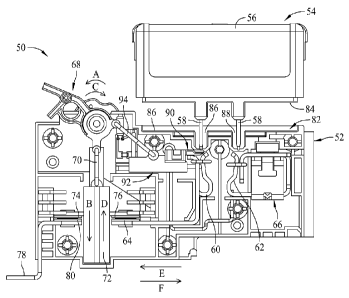
[0014] Referring now to the drawings, Figure 1 is a side elevational
view of an exemplary fused disconnect switch assembly 50 including a non-
conductive switch housing 52 configured or adapted to receive a retractable
rectangular fuse module 54. The fuse module 54 is a known assembly including a
rectangular housing 56, and terminal blades 58 extending from the housing 56.
A
primary fuse element or fuse assembly is located within the housing 56 and is
electrically connected between the terminal blades 58. Such fuse modules 54
are
known and in one embodiment the rectangular fuse module is a CUBEFu5eTM power
fuse module commercially available from Cooper/Bussmann of St. Louis,
Missouri.
[0015] A line side fuse clip 60 may be situated within the switch
housing 52 and may receive one of the terminal blades 58 of the fuse module
54. A
load side fuse clip 62 may also be situated within the switch housing 52 and
may
receive the other of the fuse terminal blades 58. The line side fuse clip 60
may be
electrically connected to a line side terminal including a stationary switch
contact 64.
The load side fuse clip 62 may be electrically connected to a load side
terminal 66.
[0016] A rotary switch actuator 68 is further provided on the switch
housing 52, and is mechanically coupled to an actuator link 70 that, in turn
is coupled
to a sliding actuator bar 72. The actuator bar 72 carries a pair of switch
contacts 74
and 76. A load side terminal 78 including a stationary contact 80 is also
provided.
Electrical connection to power supply circuitry may be accomplished in a known
manner using the line side terminal 78, and electrical connection to load side
circuitry
may be accomplished in a known manner using the load side terminal 66. A
variety
of connecting techniques are known (e.g., screw clamp terminals and the like)
and
may be utilized. The configuration of the terminals 78 and 66 shown are
exemplary
only.
[0017] Disconnect switching may be accomplished by rotating the
switch actuator 68 in the direction of arrow A, causing the actuator link 70
to move
the sliding bar 72 linearly in the direction of arrow B and moving the switch
contacts
74 and 76 toward the stationary contacts 64 and 80. Eventually, the switch
contacts
-3-
CA 02792021 2016-01-11
78400-70
74 and 76 become mechanically and electrically engaged to the stationary
contacts 64
and 80 and a circuit path may be closed through the fuse 54 between the line
and load
terminals 78 and 66 as shown in Figure 1 when the fuse terminal blades 58 are
received in the line and load side fuse clips 60 and 62.
[0018] When the actuator 68 is moved in the opposite direction
indicated by arrow C in Figure 1, the actuator link 70 causes the sliding bar
72 to
move linearly in the direction of arrow D and pull the switch contacts 74 and
76 away
from the stationary contacts 64 and 80 to open the circuit path through the
fuse 54 as
shown in Figure 8. As such, by moving the actuator 68 to a desired position,
the fuse
54 and associated load side circuitry may be connected and disconnected from
the line
side circuitry while the line side circuitry remains "live" in full power
operation.
[0019] Additionally, the fuse module 54 may be simply plugged into
the fuse clips 60, 62 or extracted therefrom to install or remove the fuse
module 54
from the switch housing 52. The fuse housing 56 projects from the switch
housing 52
and is open and accessible so that a person can grasp the fuse housing 56 by
hand and
pull it in the direction of arrow B to disengage the fuse terminal blades 58
from the
line and load side fuse clips 60 and 62 such that the fuse module 54 is
completely
released from the switch housing 52. Likewise, a replacement fuse module 54
can be
grasped by hand and moved toward the switch housing 52 to engage the fuse
terminal
blades 58 to the line and load side fuse clips 60 and 62.
[0020] Such plug-in connection and removal of the fuse module 54
advantageously facilitates quick and convenient installation and removal of
the fuse
54 without requiring separately supplied fuse carrier elements and without
requiring
tools or fasteners common to other known disconnect devices. Also, the fuse
terminal
blades 58 project from a lower side of the fuse housing 56 that faces the
switch
housing 52. Moreover, the fuse terminal blades 58 extend in a generally
parallel
manner projecting away from the lower side of the fuse module 54 such that the
fuse
housing 56 (as well as a person's hand when handling it) is physically
isolated from
the conductive fuse terminals 58 and the conductive line and load side fuse
clips 60
-4-
CA 02792021 2012-09-04
WO 2011/112293
PCT/US2011/023123
and 62. The fuse module 54 is therefore touch safe (i.e., may be safely
handled by
hand without risk of electrical shock) when installing and removing the fuse
54.
[0021] Additionally, the disconnect device 50 is rather compact and
can easily occupy less space in a fusible panelboard assembly, for example,
than
conventional in-line fuse and circuit breaker combinations. In particular,
CUBEFu5eTM power fuse modules occupy a smaller area, sometimes referred to as
a
footprint, in the panel assembly than non-rectangular fuses having comparable
ratings
and interruption capabilities. Reductions in the size of panelboards are
therefore
possible, with increased interruption capabilities.
[0022] In ordinary use, the circuit is preferably connected and
disconnected at the switch contacts 64, 74, 76 and 80 rather than at the fuse
clips 60
and 62. Electrical arcing that may occur when connecting/disconnecting the
circuit
may be contained at a location away from the fuse clips 60 and 62 to provide
additional safety for persons installing, removing, or replacing fuses. By
opening the
disconnect module 50 with the switch actuator 68 before installing or removing
the
fuse module 54, any risk posed by electrical arcing or energized metal at the
fuse and
housing interface is eliminated. The disconnect module 50 is accordingly
believed to
be safer to use than many known fused disconnect switches.
[0023] The disconnect switching device 50 includes still further
features, however, that improve the safety of the device 50 in the event that
a person
removes the fuse module 54 without operating the actuator 68 to disconnect the
circuit through the fuse module 54.
[0024] As shown in Figure 1, the switch housing 52 in one example
includes an open ended receptacle or cavity 82 on an upper edge thereof that
accepts a
portion of the fuse housing 56 when the fuse module 54 is installed with the
fuse
terminal blades 58 engaged to the fuse clips 60, 62. The receptacle 82 is
shallow in
the embodiment depicted, such that the only a small portion of the fuse
housing 56 is
received therein, which facilitates the finger safe handling of the fuse
module 54 for
installation and removal without requiring tools. It is understood, however,
that in
-5-
CA 02792021 2012-09-04
WO 2011/112293
PCT/US2011/023123
other embodiments the fuse housing 56 need not project as greatly from the
switch
housing receptacle when installed, and indeed could even be substantially
entirely
contained with the switch housing 52 if desired.
[0025] In the exemplary embodiment shown, the fuse housing 56
includes a recessed guide rim 84 having a slightly smaller outer perimeter
than a
remainder of the fuse housing 56, and the guide rim 84 is seated in the switch
housing
receptacle 82 when the fuse module 54 is installed. It is understood, however,
that the
guide rim 84 may be considered entirely optional in another embodiment and
need not
be provided.
[0026] The switch housing receptacle 82 further includes a bottom
surface 86, sometimes referred to as a floor, that includes first and second
openings 86
and 88 formed therein and through which the fuse terminal blades 58 may be
extended to engage them with the line and load side fuse clips 60 and 62. As
shown
in Figure 1 and in the magnified view in Figure 2, however, a slidable
nonconductive
terminal cover 90 is provided that closes the line side opening 86 in the
switch
housing fuse receptacle 82 and prevents the line side terminal blade 58 from
coming
into contact with the line side fuse clip 60 when the switch actuator 68 is
moved to an
"on" position. As such, the terminal cover 90 prevents a fuse module 54 from
being
installed when the switch actuator is the "on" position closing the switch
contacts 74
and 76 and hence electrically connecting the line side fuse clip 60 to power
supply
circuitry. In such a condition the line side fuse clip 60 is "live" or
energized at normal
operating power, and by preventing the line side fuse terminal 58 from coming
into
contact with it via the terminal cover 90, electrical arcing conditions that
otherwise
may occur are avoided entirely.
[0027] In the example shown, the terminal cover 90 is coupled to an
interlock element 92, that is turn coupled to the switch actuator 68 via a
positioning
arm or link 94. As the switch actuator 68 is rotated in the direction of arrow
C to
open the switch contacts 64 and 80 or open or turn the device "off' as shown
in
Figure 8, the link 94 pulls the interlock element 92 and also the terminal
cover 90
-6-
CA 02792021 2016-01-11
78400-70
along a linear axis in the direction of arrow E away from the line side fuse
clip 60,
and hence permitting access for the line side terminal blade 58 of the fuse
extend
through the line side opening 86 in the switch housing fuse receptacle 82 and
into the
line side fuse clip 60 as best seen in the magnified view of Figure 4. In this
state, the
slidable terminal cover 90 clears the line side opening 86 and permits plug-in
connection of the line side terminal blade 58 to the line side fuse clip 60 as
shown in
Figures 5 and 8.
[0028] When the switch actuator 68 is rotated in the direction of
arrow A, however, to the closed or "on" position (Figure 1) wherein the switch
contacts 74 and 76 are engaged with the stationary contacts 64 and 80, the
interlock
element 92 and the terminal cover 90 are slidably moved toward the line side
fuse clip
60 along the liner axis in the direction of arrow F. The terminal cover 90 is
accordingly moved toward the line side fuse clip 60 and blocks the line side
opening
86 in the switch housing fuse receptacle 86. As such, the terminal cover 90
effectively blocks access to the line side fuse clip 60 and would frustrate
any effort to
install the fuse module 54. The line side terminal blade 58 of the fuse module
54
would hit the terminal cover 90 during any attempt to plug the fuse module 54
into the
switch housing receptacle 82 in this condition. This is perhaps particularly
evident in
the perspective, magnified view shown in Figure 3 wherein a leading end of the
terminal cover 90 is positioned between a distal end of the line side fuse
terminal 60
and the line side opening 86 in the fuse receptacle 82.
[0029] It should now be evident that the switch actuator 68
simultaneously drives the sliding bar 72 along a first linear axis (i.e., a
vertical axis
per Figures 1 and 8 as drawn) in the direction of arrow B or D and the
slidable
interlock element 92 and terminal cover 90 along a second linear axis (i.e., a
horizontal axis per Figures 1 and 8 as drawn) in the direction of arrows E or
F.
Specifically, as the sliding bar 72 is moved in the direction of arrow B, the
interlock
element 92 and the terminal cover 90 are driven in the direction of arrow F
toward the
line side fuse clip 60. Likewise, when the sliding bar 72 is moved in the
direction of
arrow D, the interlock element 92 and the terminal cover 90 are driven in the
direction
-7-
CA 02792021 2016-01-11
78400-70
of arrow E away from the line side fuse clip 60. The mutually perpendicular
axes for
the sliding bar 72 and the interlock element 92 and terminal cover 90 are
beneficial in
that that the actuator 68 is stable in either the opened "off" position
(Figure 8) or the
closed "on" position (Figure 1) and a compact size of the disconnect device 50
is
maintained. It is understood, however, that such mutually perpendicular axes
of
motion are not necessarily required for the sliding bar 72 and the interlock
element 92
and terminal cover 90. Other axes of movement are possible and may be adopted
in
alternative embodiments. On this
note too, linear sliding movement is not
necessarily required for these elements to function, and other types of
movement (e.g.,
rotary or pivoting movement) may be utilized for these elements if desired.
[0030] Figure 6 and 7 illustrates the terminal cover 90 and interlock
element 92 in further detail. The terminal cover 90 in this embodiment is
separately
fabricated from the interlock element 92 such that the terminal cover 90 is
slidably
movable relative to the interlock element 92. Specifically, the interlock
element 92 is
formed with a channel or bore 100 that receives a bias element 102 such as a
compression spring and a shank 104 formed with the interlock cover 90. As
such, the
terminal cover 90 may be moved relative to the interlock element 92 in the
direction
of arrow E, with the shank 104 thereby compressing the bias element 102 as
shown
in Figure 7.
[0031] Thus, for example, when a fuse terminal blade 58 is received
in the line side fuse clip 62 as described above, as the interlock element 92
and
terminal cover 90 are moved toward the fuse clip 62 in the direction of arrow
F and
the leading edge of the terminal cover 90 eventually contacts the line side
terminal
blade 58 of the fuse module 54, but with the bias element 102 being partly
compressed. Meanwhile, an interlock shaft 106 provided with the interlock
element
92 is extended through an opening 108 in the terminal blade 58 as shown in
Figure 7.
The extension of the shaft 106 through the terminal blade 58 couples the shaft
106 to
the terminal blade 58 such that the terminal blade 58 cannot be disengaged
from the
line side fuse clip 60 by pulling of the fuse module in the direction of arrow
G when
the switch actuator 68 is closed and the device 50 is "on." As such, the
terminal blade
-8-
CA 02792021 2016-01-11
78400-70
58 cannot be disengaged from the line side terminal 60 when the device is "on"
as
shown in Figure 7 (also shown in Figures 1 and 5). Also, in this state, the
bias
element 102 biases the terminal cover 90 in the direction of arrow F against
the side
of the terminal blade 58.
[0032] When the switch actuator 68 is moved to its "off" position
(Figures 4 and 8), the interlock element 92 and the shaft 106 are moved in the
direction of arrow E away from the line side fuse clip 60 and the terminal
blade 58
such that the shaft 106 is withdrawn from the terminal blade opening 108 as
seen in
Figure 6 and allowing the terminal blade 58 to be withdrawn from the fuse clip
60 in
the direction of arrow G. Because of the shaft 106 in the interlock element
92, the
terminal blade 58 can only be removed when the device 50 is "off" When the
device
50 is "on" the terminal blade 58 is locked in place and cannot be withdrawn
from the
fuse clip 60.
[0033] When the terminal blade 58 is withdrawn and clears the
leading edge of the terminal cover 90, the terminal cover 90 is moved by the
bias
element 102 in the direction of arrow F so as to block the line side opening
86 in the
fuse receptacle 82 as shown in Figures 2 and 3. As such, the same or different
fuse
module 54 may not be reinserted until the switch actuator 68 is moved
completely to
the opened or "off" position wherein the leading edge of the terminal cover 90
once
again clears the line side opening 86 as shown in Figure 4 and a terminal
blade 58 of a
fuse module 54 may again be reinserted.
[0034] The terminal cover 90 and the interlock element 92 may be
fabricated from known nonconductive materials such as plastic or other
suitable
materials into various shapes, including but not limited to those depicted in
the
drawings, to accomplish the functionality described. It is contemplated that a
variety
of bias elements known in the art may be utilized in lieu of a compression
spring to
accomplish the independent movement of the cover element 90 described. It is
understood, however, that the cover element 90 need not necessarily be
independently
movable from the interlock clement 92 in at least some alternative
embodiments. For
-9-
CA 02792021 2012-09-04
WO 2011/112293
PCT/US2011/023123
instance, the terminal cover 90 and the interlock element 92 could be
integrally
combined in a single piece if desired while still achieving some of the
benefits of the
invention as described.
[0035] Further, while the combined interlock element 92 and
terminal cover 90 is believed to be advantageous for the reasons stated, it is
contemplated that these could be separately actuated and the terminal cover 90
need
not necessarily be carried on the interlock element as described. It is also
contemplated that in some embodiments one or the other of the terminal cover
90 and
the interlock element 92 could be provided, but not necessarily both while
still
obtaining some of the benefits described.
[0036] In still further adaptations, it is noted that the terminal cover
90 may be alternatively shaped and dimensioned to block both the line side and
load
side terminal openings 86 and 88 (Figure 1) in the fuse receptacle 82 rather
than only
the line side opening 86 as described. Moreover, an interlock element could be
provided to engage a load side fuse clip 62 in addition to or in lieu of the
embodiments shown in the drawings wherein only the line side fuse clip 60 is
affected
by the interlock.
[0037] This written description uses examples to disclose the
invention, including the best mode, and also to enable any person skilled in
the art to
practice the invention, including making and using any devices or systems and
performing any incorporated methods. The patentable scope of the invention is
defined by the claims, and may include other examples that occur to those
skilled in
the art. Such other examples are intended to be within the scope of the claims
if they
have structural elements that do not differ from the literal language of the
claims, or if
they include equivalent structural elements with insubstantial differences
from the
literal languages of the claims.
-10-