Note: Descriptions are shown in the official language in which they were submitted.
CA 02792155 2012-10-15
Docket No. 2600-75-00
ROCK BOLT SEALING SYSTEM
FIELD OF INVENTION
The present invention is directed to a technique and system for sealing rock
bolts to prevent the leakage of water or other liquids after the rock bolt has
been set in
to place in the roof or wall of a mine, karst zone, or other underground
structure. The
invention also pertains to a sealable rock bolt, a rock bolt kit useful in the
practice of
the invention and a sealing unit to be inserted into the rock bolt to cause
sealing.
BACKGROUND OF THE INVENTION
Rock bolts, sometimes referred to as friction rock stabilizers, are support
mechanisms designed to be placed into a drilled hole or opening in the roof,
side, or
bottom of an underground structure where such bolts are anchored and sometimes
tensioned to support the overlying structure or external utilities, such as
pipes or
mesh. Rock bolts are commonly used in applications involving mining, rail,
road and
sewer tunnels, rail and road cut throughs, soil nails for hillside supports,
hydro electric
flumes, and karst zones. Rock bolts are commonly used in or around any
structure
which requires restraint through 3600, where rock or concrete exists as an
anchoring
medium. A typical type of such rock bolt is the Split Set bolt which is sold
by
International Rollforms, Inc., Deptford, NJ. These bolts have two parts: a
tube and a
matching domed bearing plate. The tube may be slotted along its length. One
tube
end is tapered to facilitate insertion into a drill hole in the underground
structure, and
the other end has a welded ring flange to hold the bearing plate. With the
bearing
- 1 -
CA 02792155 2012-10-15
Docket No. 2600-75-00
plate in place, the tube is driven into a slightly smaller drill hole to
achieve an
interference fit and thus hold the rock bolt in place. As the tube portion of
the rock
bolt slides into place, the full length of the slot narrows causing radial
pressure to be
exerted against the rock over its full contact length and also provides
immediate plate
load support.
Split Sete rock bolts are typically manufactured by rolling or drawing a flat
length of steel to create a circular profile along the length, leaving two
ends open and
forming an open split over the length. Then one end is cut and tapered over
approximately 2 to 3 inches and welded shut while leaving the split open. Then
an
open-ended ring is welded at the opposite end to act as a retaining device for
the
bearing plates and assemblies. Figure 1 is a front view of this type of rock
bolt. As
illustrated, matched bearing plate 1 and welded-on retaining ring 2 are
associated with
split hollow tube 3 to form rock bolt 4. Split Sete rock bolts are
manufactured by
International Rollforms, Inc., Deptford, NJ.
Other types of conventional rock bolts include point anchor roof bolts, point
anchor resin roof bolts and Swel lexTm bolts.
A problem has existed regarding the use of the above-described Split Sete,
point anchor, point anchor resin, and SwellexTM rock bolts. After placing the
rock
bolts in service in the roof or wall rock of the underground structure, water
contained
in fissures in the rock leaks into the rock bolt and drains through the rock
bolt onto the
floor of the underground structure. Such drainage results in undesirable wet
conditions and can result in corrosion of the rock bolt, the need for pumping
accumulated water, increased maintenance of pumps and lines, the need to treat
water
prior to discharge as well the creation of safety issues. This long standing
problem in
- 2 -
CA 02792155 2012-10-15
Docket No. 2600-75-00
the art has not been satisfactorily addressed to date. The present invention
is believed
to address and solve such long standing problem in the art by providing a
novel
technique and system, rock bolt assembly, and kit for preventing such water
leakage.
The present invention involves the use of a water-dissolvable sealing unit
containing a
water-activated expandable hydrophobic pre-polymeric resin. Such sealing unit
is
contained within the rock bolt and functions to provide a seal against water
leakage.
Once the rock bolt assembly is in place in an underground structure and is
contacted
with water, the water dissolvable portion or outer surface of the sealing unit
becomes
dissolved by the water, which in turn permits the water-activated expandable
to hydrophobic pre-polymeric resin to react with water and seal both the
annular space
of the rock bolt assembly and any fissures present in the rock against water
leakage.
The invention of the present invention may be advantageously utilized in any
rock
bolt where annular space exists to minimize or seal against water leakage. In
the
context of the present invention, annular space means the space or open area
from the
inner diameter of the drilled or pre-formed hole to the outer diameter of the
Split Set
bolt and at the top, where the sealing unit is located, to the top of the
hole.
Other types of rock bolts, in addition to those described above, are known in
the art and include those shown in U.S. Patent Publication No. 20040161316 and
U.S.
Patent Nos. 4,537,535; 5,249,898; 5,387,060; 6,135,674; 7,073,981; and
7,338,234.
The above patent publication and patents do not contain a water-dissolvable
sealing
unit which contains a water-activated expandable hydrophobic pre-polymeric
resin
and thus do not function in the above described manner to create a seal
against water
leakage.
- 3 -
CA 02792155 2012-10-15
Docket No. 2600-75-00
SUMMARY OF THE INVENTION
The present invention involves a sealable rock bolt assembly, a rock bolt
assembly kit, and a method for sealing a rock bolt located on the roof, side,
or bottom
of an underground opening.
More specifically, the sealable rock bolt assembly comprises a bearing plate:
an elongated member having a top, bottom, and containing annular space when
placed
in a pre-formed hole in the rock to receive expanded resin; and a sealing unit
located
proximate to the annular space proximate to the rock bolt. The rock bolt may
be
solid, have a hollow interior, or utilize a cable, such as steel as the
support member.
The sealing unit comprises a container having sides and two ends and comprised
of a
water degradable material and having both ends capped with a water degradable
material and contains a liquid water activated, expandable hydrophobic pre-
polymeric
resin. The rock bolt assembly may further comprise a water-containing unit for
activation of the liquid water activated, expandable hydrophobic pre-polymeric
resin.
The present invention also includes a sealable rock bolt assembly kit
containing portions of the rock bolt, prior to assembly, installation, and
use, for
sealing rock bolts from water leakage comprising a bearing plate; an elongated
member having a top, bottom, and containing annular space proximate to the
rock
bolt when placed in a pre-formed hole in the rock to receive expanded resin;
and a
sealing unit comprising a container having sides and two ends and comprised of
a
water degradable material and having both ends capped with a water degradable
material, the container containing a liquid water activated, expandable
hydrophobic
pre-polymeric resin.
- 4 -
CA 02792155 2012-10-15
Docket No. 2600-75-00
The present invention also includes a method for sealing a rock bolt from
water
leakage comprising: inserting a sealable rock bolt assembly comprising a
bearing
plate, an elongated member having a top, bottom, and containing annular space
when
placed in a pre-formed hole in the rock to receive expanded resin; and a
sealing unit
located proximate to the annular space. The method may also be performed by
installing the sealable rock bolt assembly and then installing the sealing
unit and any
other optional components. The elongated member may have a hollow interior.
The
sealing unit comprises a container having sides and two ends and comprised of
a
water degradable material and having both ends capped with a water degradable
material. The container contains a liquid water activated, expandable
hydrophobic
pre-polymeric resin suitable to be expanded into the pre-formed hole in the
rock,
which rock contains water. Once the rock bolt is fitted into and secured in a
pre-
formed hole located in the roof, side or bottom of the rock, water present in
the rock,
such as in a fissure, contacts the sealing unit to cause the water dissolvable
materials
to dissolve. Thereby the liquid water activated, expandable hydrophobic pre-
polymeric resin is contacted with the water to form an expanded polymeric
resin
which fills and seals the annular space proximate to the rock bolt, i.e.,
between the
inner diameter of the pre-formed hole and the outer diameter of the rock bolt
to the
top of the hole, to prevent water flow from the rock through or beside the
rock bolt.
The present invention also includes another method embodiment for sealing a
rock bolt from water comprising forming an opening that has an open end and a
closed end and placing a resin-containing unit at the closed end. A sealable
rock bolt
assembly is then inserted into the opening. The rock bolt assembly comprises a
bearing plate and an elongated member having a top and bottom. Annular space
- 5 -
CA 02792155 2012-10-15
Docket No. 2600-75-00
proximate to the rock bolt is created upon insertion of the bolt into the
opening. Such
insertion causes contact with and puncture of the resin-containing unit by the
rock
bolt thereby causing the resin to cure and to secure said rock bolt assembly
at the
closed end of the pre-formed opening. Then a sealing unit is inserted into the
opening
proximate to its closed end. The sealing unit comprises a container having
sides and
two ends and comprised of a water degradable material and having both ends
capped
with a water degradable material. The sealing unit contains a liquid water
activated,
expandable hydrophobic pre-polymeric resin. Upon contact of the sealing unit
with
water, the water dissolvable materials to dissolve; and the liquid water
activated,
expandable hydrophobic pre-polymeric resin forms an expanded polymeric resin
which causes filling and sealing of the annular space proximate to the rock
bolt to
prevent water flow from the rock through or around the rock bolt. This method
embodiment may further include inserting a water-containing unit between the
closed
end and sealing unit and causing said water-containing unit to release water
to
activate the resin contained in the sealing unit. Such embodiment may be
useful in
instances where the opening is dry or does not contain sufficient water to
dissolve the
outer portions of the sealing unit or to sufficiently expand the resin
contained in the
sealing unit to achieve the desired seal.
- 6 -
CA 02792155 2012-10-15
Docket No. 2600-75-00
BRIEF DESCRIPTION OF THE DRAWINGS
Figure 1 is a front view of a Split Set type of rock bolt.
Figure 2 is a cross-sectional view of a sealing unit to be installed in a rock
bolt.
Figure 3 is a cross-sectional view of a rock bolt assembly that has been
installed in a pre-formed hole in an underground structure.
Figure 4 is a cross-sectional view of a rock bolt assembly that has been
installed in a pre-formed hole in an underground structure and then caused to
seal the
assembly following contact with water contained in the underground structure.
Figure 5 is a cross-sectional view of a rock bolt assembly having a water-
containing unit used to activate a sealing unit.
DETAILED DESCRIPTION OF THE INVENTION
The present invention is generally directed to a system and method for
preventing the harmful leakage of liquids, such as water, by sealing a rock
bolt
installed in a roof or side of an underground structure so that the liquid
cannot pass
through and around the rock bolt and leak into the interior of the underground
stricture.
The present invention is also directed to sealable rock bolts that prevent
water
leakage through the bolt and a kit containing portions of such bolts prior to
assembly,
installation, and use. The rock bolts are fastened in place in a roof, wall,
or bottom of
an underground structure via pressure fitting or the like. The rock bolts
contain a
sealing unit that contains a liquid water activated, expandable hydrophobic
pre-
polymeric resin. The sealing unit has side, top, and bottom portions that are
- 7 -
CA 02792155 2012-10-15
Docket No. 2600-75-00
degradable by water to permit the resin to expand upon contact with water and
to seal
the annular space formed when the rock bolt is inserted in a pre-formed hole
to
prevent water passage contained in the roof, wall, or bottom of the
underground
structure to pass through and or around the bolt and onto the floor of the
underground
structure.
Figure 2 is a cross-sectional view of a sealing unit that is to be installed
into a
portion of a rock bolt assembly. Sealing unit 20 is in the form of tube 21
which may
be comprised of soap or another water degradable material, such as cellulose,
treated
cardboard, rice paper, purging paper, sugar, toilet paper or tissue, water
soluble
greases, clay (including sandy clay), starch, and water-soluble resins such as
thermoplastic or thermosetting resin films. Tube 21 is capped on both ends
with salt
caps 22 and 23. Other water degradable materials, such as cellulose, treated
cardboard, may be used instead of salt. Liquid water activated,
expandable
hydrophobic pre-polymeric resin 24 is contained within sealing unit 20.
Liquid water-activated, expandable, hydrophobic pre-polymeric resin 24 is
capable of expanding to create a semi-flexible foam following contact with
water.
Hydrophobic polymeric resins, such as polyurethane, repel water during the
reactive
phase of polymerization and thus are superior to hydrophilic polymeric resins,
which
entrain water during the reactive phase of polymerization.
Hydrophobic polyurethane resins are well known in the art as grouts used to
fill voids and stabilize soils due to their low viscosity, high expansion
rate, and ability
to set up under wet conditions without diluting. The liquid water activated
pre-
polymeric resin typically is a one-component system but may be a two-component
- 8 -
CA 02792155 2012-10-15
Docket No. 2600-75-00
system. Optional ingredients such as catalysts, reaction accelerators,
hydrophobic
agents, hydrophobicity inducing surfactants, blowing agents, and other
ingredients
may be included in the pre-polymeric resins. Low viscosity resins are
particularly
suitable for use in the invention because such resins are more easily pumped.
Typical
viscosities range from about 100 Centepoise to about 500 Centepoise.
Suitable hydrophobic polymeric resins include, but are not limited to,
polyurethane, polyesters, epoxies, and polyureas. Copolymers of polymeric
resins are
also contemplated as suitable hydrophobic polymeric resins. Polyurethane
hydrophobic resins are preferred due to availability and cost considerations.
Moreover, the reactivity profile is easily controlled and a lack of
discernable
shrinkage occurs following cure.
Hydrophobic polyurethane resins may be made from isocyanate bases, such as
tolulene diisocyanate and methylene diisocyanate. A methylene diisocyanate
(MDI)
base is generally considered to constitute a less hazardous material and thus
may be
preferred for some applications, such as drinking water applications, where
water
impairment is to be avoided. The hydrophobic polyurethane foam shown in U.S.
Patent No. 6,747,068 would be suitable for use in the present invention. Other
suitable hydrophobic polyurethane resins include Prime-Flex 910 and Prime-Flex
920
supplied by Prime Resins, Inc., Conyers, GA; AV-248 Flexseal, AV-275
Soilgrout,
and AV-280 Hydrofoam supplied by Avanti International, Webster, TX; Mountain
Grout Flexible, SLV, HL-100, and Ultra supplied by Green Mountain
International,
LLC, Waynesville, NC; and Hyperflex supplied by SealGuard, Inc., (a wholly-
owned
subsidiary of Sub-Technical, Inc.), Mars, PA.
- 9 -
CA 02792155 2012-10-15
Docket No. 2600-75-00
Once the sealing unit is prepared, the unit is inserted, for example, into the
hollow interior of a rock bolt. Following such insertion, a fast reacting
polyurethane
polymer is pumped into the rock bolt to fill the hollow interior from its
bottom to the
previously-inserted sealing unit and permitted to react, leaving an open space
between
the top of the unit and the top of the rock bolt.
Pumping of the polyurethane material may be conveniently accomplished with
use of the device illustrated in U.S. Patent No. 6,955,277. Such patent
pertains to a
dispensing device and method that is adapted for use in sealing high pressure
fluid
leaks. The device requires high pressure dispensing of sealant. Suitable
sealants are
formed by an exothermic reaction of at least two liquid substances that
generate high
pressures within the dispensing device. However, high pressures could
potentially
harm the feeding system of the device due to pressure backflow. This problem
is
solved by providing a check valve in the mixing and reaction chamber of the
device to
protect the feeding system. A static mixer is disposed within the chamber to
enhance
mixing and reaction of the substances. In any event, this device is compatible
with
the instant invention along with other suitable dispensing devices.
Regarding the fast reacting polyurethane polymer, polymethylene polyphenyl
isocyanates and a curing agent, 4,4' -diphenylmethane diisocyanate, are
suitable. In
addition, all other polyurethanes which produce a rigid closed cell foam may
be used
in the invention and include, but are not limited to, single component systems
such as
prepolymeric polyurethanes with a combined catalyst.
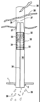
Figure 3 is a cross-sectional view of a rock bolt assembly that has been
installed in a prepared hole in an underground structure. The above-described
procedure for making a rock bolt assembly is further illustrated in this
Figure. Rock
- 10 -
CA 02792155 2012-10-15
Docket No. 2600-75-00
bolt assembly 30 contains sealing unit 31. Sealing unit 31 comprises salt caps
32 and
33 and contains expandable hydrophobic pre-polymeric resin 34 within soap tube
35.
Reacted polyurethane polymer 36 is located between the bottom of rock bolt
assembly
30 and sealing unit 31. Annular space 37 extends above sealing unit 31 and the
top of
rock bolt assembly 30. Water-containing fissures 38 and leakage droplets 39
illustrate
water leakage from rock bolt assembly 30 prior to sealing. Such water leakage
occurs
until expandable hydrophobic pre-polymeric resin 34 is caused to expand into
and
seal annular space 37 at outside diameter rock bolt assembly 30 and at pre-
formed
opening or hole at the top of rock bolt assembly 30 through contact with water
contained in fissures 38.
Figure 4 is a cross-sectional view of rock bolt assembly 30 that has been
installed in a prepared hole in an underground structure and then caused to
seal the
assembly following contact with water contained in the underground structure.
This
Figure illustrates the result of expansion of expandable hydrophobic pre-
polymeric
resin 34 (illustrated in Fig. 3) into annular space 37. As may be noted, water
has
dissolved the soap and salt components of sealing unit 30 at location 41; and
rock
bolt assembly 30 is now sealed annular space and opening 40 and extends into
fissures 38, thereby preventing further water leakage from water-containing
fissures
38 into the interior of rock bolt assembly 30.
The addition another unit having water dissolvable sides and ends and
containing water, located above the sealing unit for either vertically up and
or
vertically down holes so that gravity will allow the water contained in the
dissolvable
unit to flow down over the sealing unit once the contained water dissolves the
sides
and ends of the water-containing unit and activates the expandable hydrophobic
pre-
- 11 -
CA 02792155 2012-10-15
Docket No. 2600-75-00
polymeric resin when the container and its ends are dissolved by the released
water.
Released water from the water-containing unit will activate the expandable
hydrophobic pre-polymeric resin even when the hole itself is completely dry.
The
tube containing the water to be released will remain sealed for approximately
30
minutes to several hours, preferably about 45 minutes, before the water-
containing
tube will soften and rupture, releasing the water onto the sealing unit,
thereby causing
the sealing unit to also rupture and release the pre-polymeric resin which
will then
come into contact with the released water and allow polymerization to occur.
The
water contained in the tube may optionally contain an activator or catalyst to
speed
the reaction of the expandable hydrophobic pre-polymeric resin. The water
containing unit may be located above the sealing unit whether or not the pre-
formed
hole is vertically up or down so that the released water may be gravity fed to
the
sealing unit.
Figure 5 is a cross-sectional view of Split Set rock bolt assembly 50 in the
vertically up position that includes water-containing unit 51 which is
described in the
paragraph above and is located above sealing unit 52. In this illustration
both units
51 and 52 include salt caps 53, 54 and 55, 56 respectively. Water-containing
unit 51
contains water 57 and sealing unit 52 contains expandable hydrophobic pre-
polymeric
resin 58. Upon activation the expandable hydrophobic pre-polymeric resin
expands
into annular space 37 and serves to seal rock bolt assemble 50.
The present invention is further illustrated by the following Examples.
- 12-
CA 02792155 2012-10-15
Docket No. 2600-75-00
EXAMPLE 1
This Example pertains to the preparation of a sealed rock bolt assembly
suitable for use in the method of the invention and comprises the following
steps.
1. A sealing unit is prepared by placing a salt cap on one end of a
soap tube and then dispensing a liquid water-activated, expandable
hydrophobic pre-polymeric resin into the tube and then placing a
second salt cap on the opposite end of the soap tube;
2. Inserting the prepared sealing unit inside a hollow Split Set rock
bolt toward the tapered end of the rock bolt;
3. Dispensing a heavy bead of a fast reacting polyurethane polymer
into the interior of the rock bolt to form a cured foamed reaction
product located between the sealing unit and the bottom portion of
the rock bolt; and
4. Trimming any excess of foamed material from the rock bolt.
As noted above, this Examples 1, 2, and 3 may be performed by inserting the
sealing unit inside the Split Set rock bolt before or after insertion of the
rock bolt
prior to or following placement of the rock bolt into a pre-formed hole or
opening.
EXAMPLE 2
This example pertains to the installation of a rock bolt assembly into rock of
an
underground structure and comprises the following steps.
1. A hole of suitable diameter and length is drilled into rock;
2. Inserting a chuck protrusion into the upper end of the rock bolt
assembly and fitting bearing plates onto the assembly; and
- 13-
CA 02792155 2012-10-15
Docket No. 2600-75-00
3. Engaging the rock bolt assembly into the drilled hole and, using
the drill head, hammering the rock bolt assembly into the hole until
it is fully inserted. The rock bolt assembly will become secured in
the drilled hole due to an interference fit. Once the rock bolt
assembly is in place, the unit is upon contact with water in the
manner described above, i.e., the soap and salt will be dissolved by
the water, which in turn will permit the water-activated expandable
hydrophobic pre-polymeric resin to react with water and seal both
the annular space of the rock bolt assembly and any fissures
present in the rock.
EXAMPLE 3
After a Split Sete roof bolt has been installed in the rock, the bolt can be
waterproofed by the following method. First, prepare a soap tube unit with a
water
activated, expandable hydrophobic pre-polymeric and also a unit containing
water.
Then both units are slid up the center of the Split Sete bolt and secured at
the top of
the bolt with use of a plug, such as balled rag or burlap. Then take a tube of
our two
component rigid foam, enter the nozzle of the tube into the opening of the
Split Sete
bolt and seal around the opening with a rag or burlap, then dispense resin
from the
tube to refusal (the resinous material has a 3+ second reaction time). Once
finished,
the nozzle and rag or burlap are removed. This procedure then waterproofs a
Split
Set bolt in-situ. The rigid foam induced into the bottom portion of the Split
Sete
bolt will, depending upon its density, increase the pull out force required.
Also of
- 14 -
CA 02792155 2012-10-15
Docket No. 2600-75-00
course the force required to insert the bolt will be higher. Having a higher
pull out
strength is an advantage in ground control.
Although the above Examples pertain to Split Set rock bolts, those skilled in
the art would understand that the principles underlying the present invention
are
generally applicable for any rock bolt where annular space proximate to an
inserted
rock bolt exists to minimize or seal against water leakage, including other
types of
conventional rock bolts such as point anchor roof bolts, point anchor resin
roof bolts
and SwellexTM bolts. Accordingly, the rock bolts of the invention may be
solid, have a
hollow interior, or utilize a cable, such as steel, as the support member.
When a solid or cable rock bolt is installed in a roof or the like, a resin-
containing unit or cartridge, such as a polyester-containing unit, is first
inserted at the
top of the pre-formed hole. This serves as the primary anchor for the bolt
end. The
bolt is then pushed up into the hole and punctures the film surrounding the
cartridge.
The solid or cable bolt is then spun to mix the resin and then the bolt is
held in place
once the resin becomes set. In the present invention, an additional cartridge
or sealing
unit, such as that described in connection with Figure 2, is placed in the pre-
formed
hole following placement of the resin-containing cartridge. Then as the bolt
is
inserted into the hole, it will puncture the sealing unit, release the
contained
expandable hydrophobic pre-polymeric resin located underneath the resin-
containing
cartridge, continue up the hole to puncture the resin-containing cartridge,
and then
spin the resin to establish bolt anchoring. Once the sealing unit is
punctured, the
released resin will migrate or flow down the length of the hole and sides of
the bolt
and react with water to seal the bolt from subsequent water leakage. Should
the hole
be dry when the above procedure is performed, a water-containing unit, such as
-15-
CA 02792155 2012-10-15
Docket No. 2600-75-00
described in connection with Figure 5, can be employed. In such instance, the
resin-
containing unit is inserted, followed by the water-containing unit, and
finally by the
sealing unit. Such arrangement permits water to flow downwardly and activate
the
resin contained in the sealing unit.
Point anchor bolts utilize a split wedge type retainer included with the bolt
on
the opposite end to the head of the bolt. A hole is drilled into the rock and
the bolt
inserted. The retainer grips the inside of the hole and, as the bolt is
rotated, the
retainer expands to the inside of the hole and simultaneously draws the bolt
tight
between the anchor point and the head of the bolt on the outside of the hole.
This
procedure secures the bolt to a specified torque value. Point anchor bolts are
manufactured by Jennmar Corporation, Pittsburgh, PA. The present invention can
be
used for point anchor roof bolts by placing a sealing unit and a water-
containing unit
ahead of the bolt, so that when the bolt is pushed into the hole, the units
rupture and
water and the water-activated expandable hydrophobic pre-polymeric resin react
and
the expanded resin fills the annular region surrounding the bolt. This
procedure serves
to protect all of the bolt and its mechanism from corrosion and serves to
waterproof
the bolt. Optionally a rubber washer may be included between the bearing plate
and
roof, sidewall, or floor tom seal from potential water dripping.
Point anchor rock bolts are quite similar to conventional point anchor rock
bolts. Such bolts are manufactured by Jennmar Corporation, Pittsburgh, PA, and
a
typical point anchor resin rock bolt of Jennmar Corporation is illustrated in
U.S.
Patent No. 7,073, 982. During installation of the bolt, a hole is drilled and
a single
resin-containing unit in the form of a cartridge is pushed into the hole ahead
of the
bolt. As the cartridge reaches depth, the cartridge ruptures and as it rotates
and the
-16-
CA 02792155 2012-10-15
Docket No. 2600-75-00
resin and hardener are mixed and form a cured resin around the head of the
bolt. The
roof bolt is held in place for several seconds so that the resin can react and
cure. In
using the present invention for a point anchor rock bolt, a sealing unit is
pushed
behind the resin cartridge and ruptured first by the sharp leading end of the
rock bolt
or cable bolt while then continuing to mix the resin and secure the end of the
bolt.
This procedure permits the water-activated expandable hydrophobic pre-
polymeric
resin to react and the expanded resin to seal the annular space proximate to
the rock
bolt.
SwellexTM bolts are manufactured from a steel tube and are sealed at one end
and have a threaded pressure connection at the head end. This type of bolt is
inserted
into a pre-drilled hole and secured in place when a high pressure water pump
is
connected to the exposed end and pressure applied. Such procedure causes the
bolt to
swell inside the hole and tightly conform to the inside of the hole over the
entire
length. A bearing plate similar to that of the other above-described bolts is
included
in the assembly. SwellexTM bolts are manufactured by Atlas Copco, through
Minova
Americas, Georgetown, KY. The present invention may be used for SwellexTM
bolts
by inserting a sealing unit, followed by the bolt into a pre-drilled hole. The
sealing
unit would then be ruptured thus permitting the water-activated expandable
hydrophobic pre-polymeric resin to react with water and fill and seal the
annular
space. A water-containing unit may be used to supply water as needed.
It should be further noted that liquid water activated, expandable hydrophobic
pre-polymeric resin may be applied to the surface of cable bolts and all other
types of
rock bolts and then the bolt be inserted into the roofõ bottom, or wall. The
resin will
expand to seal the annular space proximate to the roof bolt and surround the
bolt, thus
-17-
CA 02792155 2012-10-15
Docket No. 2600-75-00
protecting it from corrosion. In addition this embodiment will serve to
somewhat
increase the holding power of the bolt.
-18-