Note: Descriptions are shown in the official language in which they were submitted.
CA 02792282 2012-10-12
Emergency Filter System for Encapsulated Suit
CROSS-REFERENCE TO RELATED APPLICATIONS
100011 None.
STATEMENT REGARDING FEDERALLY SPONSORED
RESEARCH OR DEVELOPMENT
100021 Not applicable.
REFERENCE TO A MICROFICHE APPENDIX
10003] Not applicable.
BACKGROUND
[00041 Encapsulated protective suits may be worn in contaminated areas to
protect the
wearer of the suit. For example, workers may wear an encapsulated protective
suit while
working inside of a nuclear powered electrical generating plant or in the
presence of radioactive
materials. An encapsulated protective suit may be a one-time use type of
system, wherein after a
single use the suit is disposed of. An encapsulated protective suit may
receive breathing air
during normal operating conditions via an external air flow hose connected to
the suit. The air
may be supplied, for example, by a power air purifying respirator (PAPR) that
may be carried by
the user.
SUMMARY
100051 In an embodiment, an encapsulated protective suit is disclosed. The
encapsulated
protective suit having an external air flow hose comprises a skin, a filter
incorporated in the skin
of the protective suit, and a seal, wherein when the seal is intact, air does
not flow through the
filter.
100061 In an embodiment, an encapsulated protective suit is disclosed. The
encapsulated
protective suit having an external air flow hose comprises a skin, a filter
incorporated in the skin
of the protective suit, the filter having an exterior face and an interior
face, where the exterior
face of the filter faces towards an exterior of the protective suit and
wherein the interior face of
1
CA 02792282 2012-10-12
the filter faces towards an interior of the protective suit, a first seal
coupled to one of the exterior
of the suit or the exterior face of the filter, and a second seal coupled to
one of the interior of the
suit or the interior face of the filter.
[0007] In an embodiment, a method of using a fully encapsulated protective
suit is disclosed.
The method comprises donning a protective suit, the protective suit having an
external air flow
hose and comprising a skin, a filter incorporated in the skin of the
protective suit, and a first seal,
wherein when the first seal is intact, air does not flow out through the
filter from an interior of
the protective suit. The method further comprises, after donning the
protective suit, breaching
the first seal, and, after breaching the first seal, inhaling air received
from the filter.
[0008] These and other features will be more clearly understood from the
following detailed
description taken in conjunction with the accompanying drawings and claims.
BRIEF DESCRIPTION OF THE DRAWINGS
[0009] For a more complete understanding of the present disclosure, reference
is now made
to the following brief description, taken in connection with the accompanying
drawings and
detailed description, wherein like reference numerals represent like parts.
[0010] FIG. 1 illustrates an encapsulated protective suit according to an
embodiment of the
disclosure.
[0011] FIG. 2 illustrates an emergency air breathing apparatus for use with an
encapsulated
protective suit according to an embodiment of the disclosure.
[0012] FIG. 3A illustrates a sealed air filter according to an embodiment of
the disclosure.
[0013] FIG. 3B illustrates an unsealed air filter according to an embodiment
of the
disclosure.
[0014] FIG. 3C illustrates an air flow of an emergency air breathing apparatus
coupled to an
encapsulated protective suit according to an embodiment of the disclosure.
[0015] FIG. 4 illustrates an emergency air breathing apparatus for use with an
encapsulated
protective suit according to another embodiment of the disclosure.
2
CA 02792282 2012-10-12
DETAILED DESCRIPTION
100161 It should be understood at the outset that although illustrative
implementations of one
or more embodiments are illustrated below, the disclosed systems and methods
may be
implemented using any number of techniques, whether currently known or not yet
in existence.
The disclosure should in no way be limited to the illustrative
implementations, drawings, and
techniques illustrated below, but may be modified within the scope of the
appended claims along
with their full scope of equivalents.
100171 Turning now to FIG. 1, an encapsulated protective suit 100 is
described. In an
embodiment, the protective suit 100 having an external air flow hose 101,
comprises a skin 102
and a first emergency breathing apparatus 104. In an alternative embodiment,
the suit 100 may
comprise a different emergency breathing apparatus. The user dons or puts on
the suit 100 and
may further don or put on booties, shoes, or boots on the feet to protect the
integrity of the feet of
the suit 100 and gloves to seal the suit 100 at the hands. The suit 100 may be
a fully
encapsulated protective suit. Air for breathing under normal operating
conditions may be
provided by an external air hose 101 coupled to the suit 100, for example an
air hose 101 coupled
to a powered air purifying respirator device (not shown), and air within the
suit 100 is breathed
by the user. In an embodiment, an exhaust valve (not shown) coupled to the
suit 100 allows air
to leave the suit, possibly maintaining an appropriate pressure differential.
The suit 100 may be
used in any contaminated environment, for example a workplace having
radioactive materials
and/or a nuclear powered electrical power generation facility. The suit 100
may be used as well
in other contaminated environments. It is understood that in different
embodiments the suit 100
may take different forms from that illustrated in FIG. 1. While illustrated as
centered in FIG. 1,
the first emergency breathing apparatus 104 may be offset to either side of a
center of the suit
100 and/or moved up or down.
100181 While using the suit 100 in the contaminated environment, in an
embodiment, it is
preferred that a positive pressure differential be maintained between the
interior and exterior of
3
CA 02792282 2012-10-12
the suit 100. This positive pressure differential may provide a margin of
safety, in that if a minor
breach of the skin 102 occurs, contaminated material is not likely to enter
the suit 100 but rather
may be discouraged from entry by air flowing from the interior to the exterior
of the suit 100 at
the location of the minor breach. Generally it is desired that the suit 100 be
relatively air-tight,
with the exception of the exhaust valve described above, to promote
efficiency. For example, if
the normal air supply is provided by a powered air purifying respirator that
is battery powered, a
low efficiency encapsulated protective suit ¨ that is a suit that has
unnecessary air escape points ¨
may cause the powered air purifying respirator to work harder to maintain the
desired pressure
differential and may prematurely discharge the battery. Alternatively, an
inefficient suit may
entail using a heavier battery in the powered air purification respirator and
the disadvantages
associated with excess weight.
[0019] When the powered air purifying respirator or other source of air flow
fails, the user of
the suit 100 may employ the first emergency breathing apparatus 104 to breathe
safely. It is
expected that the user of the suit 100, when normal air flow fails, will begin
returning to a safe
area shortly after the normal air flow source fails, and hence it is
contemplated that the first
emergency breathing apparatus 104 will be used for relatively short time
intervals, for example
for less than 2 minutes, for less than 6 minutes, or for less than 10 minutes.
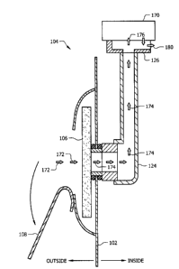
[0020] Turning now to FIG. 2, the first emergency breathing apparatus 104 is
discussed. In
an embodiment, the first emergency breathing apparatus 104 comprises a filter
106, a seal 108, a
filter coupling 120, a breathing pipe coupling 122, an breathing pipe 124, and
a mouth piece 126.
It is understood that the first emergency breathing apparatus 104 may comprise
other
components that are not illustrated or described herein. The first emergency
apparatus 104
and/or the filter 106 may be said to be incorporated into the skin 102 of the
encapsulated
protective suit 100. Additionally, the view presented in FIG. 2 is schematic
and not intended to
represent relative sizes or scale of the illustrated components. The inside of
the encapsulated
protective suit 100 is to the right of the skin 102 and the outside of the
encapsulated protective
4
CA 02792282 2012-10-12
suit 100 is to the left of the skin 102 as illustrated in FIG. 2. The outside
of the encapsulated
protective suit 100 may be referred to in some contexts as the exterior of the
encapsulated
protective suit 100 and the inside of the encapsulated protective suit 100 may
be referred to in
some contexts as the interior of the encapsulated protective suit 100.
[0021] Under normal operation, that is when the user of the encapsulated
protective suit 100
is breathing air provided via an external air hose, the seal 108 blocks flow
into and out of the
filter 106. This blockage by the seal 108 contributes to the air-tightness of
the suit 100 and
promotes the efficiency of the suit 100. When emergency air supply is needed,
the seal 108 is
torn at least partially free of the skin 102 and/or free of the filter 106,
opening a pathway for air
to flow in through the filter 106, through the couplings 120, 122, up the
breathing pipe 124, to
the mouth piece 126. The portion of the filter 106 facing to the left in FIG.
2 may be referred to
as an exterior face or an outside face of the filter 106; the portion of the
filter 106 facing to the
right in FIG. 2 may referred to as an interior face or an inside face of the
filter 106.
[0022] In an embodiment, the filter 106 may be a pancake type filter. Pancake
type filters
are known in the art and may take a variety of different forms. In an
embodiment, a pancake
type filter may be substantially cylindrical in shape where the height of the
cylinder is much less
than the width or diameter of the cylinder. For example, in an embodiment, the
height of the
cylinder may be less than 20% of the width or diameter of the cylinder.
Alternatively, in an
embodiment, the height of the cylinder may be less than 10% of the width or
diameter of the
cylinder. While pancake filters may be generally circular in section, in an
embodiment, the
pancake filter may be polygonal in section or elliptical in section. In an
embodiment, the filter
106 may be a P3 filter. Alternatively, in an embodiment, the filter 106 may be
a P2 filter.
Alternatively, in an embodiment, the filter 106 may be a P1 filter. As is
known by one skilled in
the art, a P3 filter may filter at least 99.95% of airborne particles; a P2
filter may filter at least
94% of airborne particles; and a P1 filter may filter at least 80% of airborne
particles. In other
embodiments, however, the filter 106 may be a different filter.
5
CA 02792282 2012-10-12
100231 Turning now to FIG. 3A and FIG. 3B, further details related to the seal
108 and the
filter 106 are described. In an embodiment, the seal 108 is secured in a
sealing position by a
tearable weld 150. In other embodiments, however, another means may be used to
secure the
seal 108, for example an adhesive. Tearable welds and non-tearable welds are
generally known
in the art. Without limitation, a tearable weld may be distinguished as being
an attachment or
coupling between two structures that yields or releases when a first one of
the structures is pulled
away from the second structure before either structure is damaged. By
contrast, without
limitation, a non-tearable weld may be distinguished as being an attachment or
coupling between
two structures such that damage to one of the structures is likely to occur if
a first one of the
structures is pulled away from the second structure before the non-tearable
weld yields.
100241 When the user of the encapsulated protective suit 100 wishes to use the
first
emergency breathing apparatus 104, the user may grasp the edge of the seal 108
and tear it
downwards to breach the seal between the skin 102 and/or the filter 106 and
the seal 108. It is
understood that the term seal may be used to refer to the structure seal 108
that in part establishes
a seal, meaning a barrier, between the exterior and interior of the suit 100
as well as to refer to
the state of the existence of the barrier. When the seal 108 blocks flow into
and out of the filter
106, the seal established between the seal 108 and the skin 102 and/or the
filter 106 may be said
to be intact. In an embodiment, the seal 108 may also be secured to the skin
102 and/or the filter
106 by a non-tearable weld 152 or other structure. As shown in FIG. 3B, when
the seal 108 is
torn free from the tearable weld 150 to open the first emergency breathing
apparatus 104, the
non-tearable weld 152 may retain the seal 108 coupled to the suit 100 so that
the seal 108 is not
separated. If the seal 108 were completed separated, it may fall and create a
foreign material
incident in a contaminated area (FMI). In another embodiment, however, the
seal 108 may not
be retained by the non-tearable weld 152.
100251 Turning now to FIG. 3C, the flow of air using the first emergency
breathing
apparatus 104 is described. As illustrated in FIG. 3C, the seal 108 has been
torn free from the
6
CA 02792282 2012-10-12
tearable weld 150 and is retained by the non-tearable weld 152. Exterior air
flow 172 enters the
filter 106, breathing pipe air flow 174 proceeds through the breathing pipe
124 to the mouth
piece 126 where emergency filtered air flow 176 is breathed by the user 170.
The exhaled air
flow 180 escapes from the mouth piece 180 either through an outflow valve or
through user
control of exhaled air. In an embodiment, a one-way air flow valve (not shown)
may be
incorporated in the first emergency breathing apparatus 104 to permit flow
through the filter 106
from the outside to the inside, as illustrated in FIG. 3C, and to
substantially block flow through
the filter 106 from the inside of the suit 100 to the outside of the suit 100.
The view presented in
FIG. 3C is schematic and not intended to represent relative sizes or scale of
the illustrated
components.
[0026] Turning now to FIG. 4, a second emergency breathing apparatus 200 is
described.
Some of the features of the second emergency breathing apparatus 200 are
substantially similar
to those of the first emergency breathing apparatus 104 described above. The
view presented in
FIG. 4 is schematic and not intended to represent relative sizes or scale of
the illustrated
components.
[0027] The filter 106 used in the second emergency breathing apparatus 200 may
be a
moisture laden or moisture bearing filter. The principle of operation of the
filter 106 used in the
second breathing apparatus 200 may depend upon the moisture contained within
the filter 106.
For example, the filter 106 in the second breathing apparatus 200 may be a
tritium filter. As is
known to those skilled in the art, tritium is a radioactive isotope of
hydrogen that may be
encountered in nuclear reactor work environments and poses significant health
risks to workers
who may inhale tritium. To assure that the filter 106 in the second breathing
apparatus 200
remains moist, the filter 106 may be sealed in the encapsulated protective
suit 100 on both an
exterior and interior of the suit 100. Thus, the seal 108 may be coupled to
the exterior of the skin
102 and/or the exterior of the filter 106, and the seal 202 may be coupled to
the interior of the
skin 102 and/or the interior of the filter 106.
7
CA 02792282 2012-10-12
[0028] Before donning the encapsulated protective suit 100, a user may tear
down the seal
202. After tearing down the seal 202, the user may couple the filter air
coupler 122a with the
breathing pipe air coupler 122b. Then when the user needs to employ the second
breathing
apparatus 200, for example in emergency breathing situation, the user tears
open the seal 108 and
breathes through the mouthpiece 126 as described above with reference to the
first emergency
breathing apparatus 104. In an embodiment, a one-way air flow valve (not
shown) may be
incorporated in the emergency breathing apparatus 200 to permit flow through
the filter 106 from
the outside of the suit 100 to the inside of the suit 100, and to
substantially block flow through
the filter 106 from the inside of the suit 100 to the outside of the suit 100.
[0029] While several embodiments have been provided in the present
disclosure, it should be
understood that the disclosed systems and methods may be embodied in many
other specific
forms without departing from the spirit or scope of the present disclosure.
The present examples
are to be considered as illustrative and not restrictive, and the intention is
not to be limited to the
details given herein. For example, the various elements or components may be
combined or
integrated in another system or certain features may be omitted or not
implemented.
[0030] Also, techniques, systems, subsystems, and methods described and
illustrated in the
various embodiments as discrete or separate may be combined or integrated with
other systems,
modules, techniques, or methods without departing from the scope of the
present disclosure.
Other items shown or discussed as directly coupled or communicating with each
other may be
indirectly coupled or communicating through some interface, device, or
intermediate component,
whether electrically, mechanically, or otherwise. Other examples of changes,
substitutions, and
alterations are ascertainable by one skilled in the art and could be made
without departing from
the spirit and scope disclosed herein.
8