Language selection

Search

Patent 2792303 Summary

Third-party information liability

Some of the information on this Web page has been provided by external sources. The Government of Canada is not responsible for the accuracy, reliability or currency of the information supplied by external sources. Users wishing to rely upon this information should consult directly with the source of the information. Content provided by external sources is not subject to official languages, privacy and accessibility requirements.

Claims and Abstract availability

Any discrepancies in the text and image of the Claims and Abstract are due to differing posting times. Text of the Claims and Abstract are posted:

  • At the time the application is open to public inspection;
  • At the time of issue of the patent (grant).
(12) Patent Application: (11) CA 2792303
(54) English Title: WIND TURBINE ROTOR BLADE
(54) French Title: PALE DE ROTOR D'EOLIENNE
Status: Dead
Bibliographic Data
(51) International Patent Classification (IPC):
  • F03D 1/06 (2006.01)
(72) Inventors :
  • JAQUEMOTTE, KLAUS-PETER (Germany)
(73) Owners :
  • WOBBEN PROPERTIES GMBH (Germany)
(71) Applicants :
  • WOBBEN PROPERTIES GMBH (Germany)
(74) Agent: OYEN WIGGS GREEN & MUTALA LLP
(74) Associate agent:
(45) Issued:
(86) PCT Filing Date: 2011-03-09
(87) Open to Public Inspection: 2011-09-15
Examination requested: 2012-09-06
Availability of licence: N/A
(25) Language of filing: English

Patent Cooperation Treaty (PCT): Yes
(86) PCT Filing Number: PCT/EP2011/053563
(87) International Publication Number: WO2011/110605
(85) National Entry: 2012-09-06

(30) Application Priority Data:
Application No. Country/Territory Date
10 2010 002 720.0 Germany 2010-03-10

Abstracts

English Abstract

The invention relates to a wind turbine rotor blade comprising a root (131), a tip (132), a front edge (133) and a rear edge (134). Said rotor blade also has a pressure side (136) and a suction side (135) and at least one web (200) arranged at least partially between the suction and the pressure side (135, 136). Said rotor blade comprises a longitudinal direction extending between the root (131) and the tip (132). The web (200) is wave-shaped in the longitudinal direction of the rotor blade.


French Abstract

L'invention concerne une pale de rotor d'éolienne qui comporte un pied (131), un bout (132), un bord d'attaque (133) et un bord de fuite (134). La pale de rotor comporte également un intrados (136) et un extrados (135), ainsi qu'au moins une entretoise (200) située au moins partiellement entre l'extrados et l'intrados (135, 136). En outre, la pale de rotor présente une direction longitudinale qui s'étend entre le pied (131) et le bout (132). L'entretoise (200) présente une forme ondulée dans la direction longitudinale de la pale de rotor.

Claims

Note: Claims are shown in the official language in which they were submitted.


CLAIMS


1. A wind power installation rotor blade comprising
a rotor blade root (131), a rotor blade tip (132), a rotor blade
leading edge (133) and a rotor blade trailing edge (134),
a pressure side (136) and a suction side (135), and
at least one web (200) at least partially between the suction and
pressure sides (135, 136),
wherein the rotor blade has a longitudinal direction between the
rotor blade root (131) and the rotor blade tip (132),
characterised by a wave-shaped configuration of the web in the
longitudinal direction of the rotor blade.

2. A rotor blade according to claim 1 further comprising spars at the
pressure side (136) and/or the suction side (135), wherein the at least one
web (200) is fixed in the region of the spars.

3. A rotor blade according to claim 1 or claim 2 characterised by a
web produced by hot shaping of fibre-reinforced thermoplastic materials.

4. A rotor blade according to one of the preceding claims
characterised by a sinusoidal configuration for the wave shape of the web.
5. A rotor blade according to one of the preceding claims
characterised by at least two substantially mutually parallel webs.

6. Use of webs of a wave-shaped configuration in the production of a
wind power installation rotor blade.

7. A wind power installation having at least one rotor blade according
to one of claims 1 to 5.

8. A process for the production of a wind power installation rotor
blade which has a rotor blade root (131), a rotor blade tip (132), a rotor
blade leading edge (133), a rotor blade trailing edge (134), a pressure side
(136) and a suction side (135), comprising the steps:


6

providing a web of a wave-shaped configuration in the longitudinal
direction of the rotor blade.

9. A process according to claim 8 wherein the at least one web is
produced by hot shaping of fibre-reinforced thermoplastic materials.

Description

Note: Descriptions are shown in the official language in which they were submitted.


CA 02792303 2012-09-06

1
Wind turbine rotor blade

The present invention concerns a wind power installation rotor blade.
DE 103 36 461 describes a wind power installation rotor blade,
wherein spars of composite fibre materials are provided in a rotor blade in
the longitudinal direction. Those spars can be made for example from glass
fibre-reinforced fibres, for example by impregnation in a resin. The spars
are typically provided both at the suction side of the rotor blade and also at
the pressure side. The spares can be produced beforehand and then fitted
into the rotor blades or half-shell portions. That has the advantage that the
spars can be produced beforehand under constant conditions. In particular
that is intended to avoid the spars becoming wavy during production.
Waviness of the spars is unwanted because the spars serve to carry loads.
Thus it is necessary to provide quality assurance to prevent the spars
becoming wavy or undulating.
An object of the present invention is to provide a wind power
installation rotor blade which permits inexpensive manufacture.
As general state of the art attention is directed to DE 10 2008 022
548 Al and DE 203 20 714 U1.
That object is attained by a wind power installation rotor blade
according to claim 1.
Thus there is provided a wind power installation rotor blade. The
rotor blade has a rotor blade root, a rotor blade tip, a rotor blade leading
edge and a rotor blade trailing edge. The rotor blade further has a
pressure side and a suction side as well as at least one web at least
partially between the suction and pressure sides. The rotor blade has a
longitudinal direction between the rotor blade root and the rotor blade tip.
The web is of a wave-shaped configuration in the longitudinal direction of
the rotor blade.
In an aspect of the present invention the rotor blade has spars at the
pressure side and at the suction side. The at least one web is fixed in the
region of the spars.


CA 02792303 2012-09-06

2
In a further aspect of the present invention the web is produced by
hot shaping of fibre-reinforced thermoplastic materials.
In a further aspect of the present invention the wave shape of the
web is of a sinusoidal configuration.
In a further aspect of the present invention there are provided at
least two substantially mutually parallel webs.
The invention also concerns a use of webs of a wave-shaped
configuration in the production of a wind power installation rotor blade.
The invention also concerns a wind power installation having at least
one rotor blade as described hereinbefore.
The invention is based on the concept of providing a wind power
installation rotor blade having webs between the pressure side and the
suction side of the rotor blade. The webs are not straight in longitudinal
section, but are of a web-shaped or undulating configuration.
Thus there is provided a wavy or undulating or a sinusoidally wavy
web or spar web. The spar web can be produced for example from fibre-
reinforced thermoplastic materials so that an automatic production line can
be implemented for example by hot shaping of the fibre-reinforced
thermoplastic materials. Preferably the fibre-reinforced thermoplastic
materials are unwound from a roll.
Preferably the webs are produced by machine from thermoplastic
material. As an alternative thereto the webs can be produced from pre-
preps with subsequent UV hardening.
The webs serve to increase the strength of the rotor blade. For that
purpose the webs can be provided between the suction and pressure sides
of the rotor blade. The webs can be fixed or glued for example to the spars
provided along the pressure side and the suction side. Those webs serve
only for providing strength, but not for carrying away the load within the
rotor blade.
Further configurations of the invention are subject-matter of the
appendant claims.
Advantages and embodiments by way of example of the invention
are described in greater detail hereinafter with reference to the drawing.


CA 02792303 2012-09-06

3
Figure 1 shows a diagrammatic view of a wind power installation
according to the invention,
Figure 2 shows a cross-section of a wind power installation rotor
blade for the wind power installation of Figure 1, and
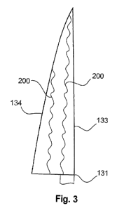
Figure 3 shows a longitudinal section of a wind power installation
rotor blade for the wind power installation of Figure 1
Figure 1 shows a diagrammatic view of a wind power installation
according to the invention. The wind power installation 100 has a pylon
110 with a pod 120 at the upper end of the pylon 110. For example three
rotor blades 130 are arranged on the pod 120. The rotor blades 130 have
a rotor blade tip 132 and a rotor blade root 131. The rotor blades 130 are
fixed at the rotor blade root 131 for example to the rotor hub 121. The
pitch angle of the rotor blades 130 is preferably controllable in accordance
with the currently prevailing wind speed.
Figure 2 shows a cross-section of a wind power installation rotor
blade according to a first embodiment. As shown in Figure 1 the rotor
blade 130 has rotor blade tip 132 and a rotor blade root 131. The rotor
blade 130 also has a leading edge 133 and a trailing edge 134.
Furthermore the rotor blade 130 has a suction side 135 and a pressure side
136. Webs or spar webs 200 can be provided between the pressure and
the suction sides 136, 135 at least partially along the length of the rotor
blade (between the rotor blade root and rotor blade tip 131, 132). The
webs have a first end 201 and a second end 202. The first end 201 is fixed
to the suction side 135 and the second end 202 is fixed to the pressure side
136. In other words the webs are mechanically connected to the suction
side and the pressure side. The webs 200 are preferably provided to
improve the mechanical stability of the rotor blades. The webs can be
provided continuously or at least partially along the length or the
longitudinal direction of the rotor blade between the rotor blade root 131
and the rotor blade tip 132.
In the first embodiment the webs 200 are of an undulating
configuration, a wave-shaped configuration or a sinusoidal configuration,
along the longitudinal direction. Alternatively thereto the webs 200 can


CA 02792303 2012-09-06

4
also be in the form of a sawtooth or a triangular undulation along the
longitudinal direction.
The webs can serve to transmit a part of the lift force from the
pressure side to the suction side. The webs can thus transmit forces
perpendicularly to their longitudinal direction, that is to say from the
pressure side of the rotor blade to the suction side. The webs however are
less suited to transmitting forces in the longitudinal direction thereof.
Figure 3 shows a longitudinal section of a wind power installation
rotor blade for the wind power installation of Figure 1. The rotor blade has
a rotor blade root 131, a rotor blade tip 132, a rotor blade leading edge
133 and a rotor blade trailing edge 134. In addition webs 200 extend
between the pressure side and the suction side of the rotor blade (as
shown in Figure 2). Those webs 200 are of a wave-shape, undulating or
sinusoidal configuration along the longitudinal direction of the rotor blade.
Alternatively thereto the webs 200 can also be in the form of a sawtooth or
a triangular undulation.
The webs shown in Figures 2 and 3 can be made by machine for
example from a thermoplastic material. That can be effected for example
by hot shaping of fibre-reinforced thermoplastic materials.
The webs can be produced in particular from rolled-up fibre-
reinforced thermoplastic materials, in which case the wave shape can be
produced by the hot shaping operation.
A saving in material of between 10% and 20% (in particular 15%)
can be achieved by those webs of a wave-shaped configuration. As the
webs are of a wave-shaped or undulating configuration in the longitudinal
direction they do not contribute to carrying load so that the load is still
carried away as previously by way of fibre-reinforced spars provided at the
pressure and suction sides. On the other hand a lift force caused by the
wind can be transmitted for example in a proportion of 90% by way of the
webs 200.

Representative Drawing
A single figure which represents the drawing illustrating the invention.
Administrative Status

For a clearer understanding of the status of the application/patent presented on this page, the site Disclaimer , as well as the definitions for Patent , Administrative Status , Maintenance Fee  and Payment History  should be consulted.

Administrative Status

Title Date
Forecasted Issue Date Unavailable
(86) PCT Filing Date 2011-03-09
(87) PCT Publication Date 2011-09-15
(85) National Entry 2012-09-06
Examination Requested 2012-09-06
Dead Application 2015-03-10

Abandonment History

Abandonment Date Reason Reinstatement Date
2014-03-10 FAILURE TO PAY APPLICATION MAINTENANCE FEE
2014-05-13 R30(2) - Failure to Respond

Payment History

Fee Type Anniversary Year Due Date Amount Paid Paid Date
Request for Examination $800.00 2012-09-06
Application Fee $400.00 2012-09-06
Maintenance Fee - Application - New Act 2 2013-03-11 $100.00 2012-09-06
Owners on Record

Note: Records showing the ownership history in alphabetical order.

Current Owners on Record
WOBBEN PROPERTIES GMBH
Past Owners on Record
None
Past Owners that do not appear in the "Owners on Record" listing will appear in other documentation within the application.
Documents

To view selected files, please enter reCAPTCHA code :


To view images, click a link in the Document Description column. To download the documents, select one or more checkboxes in the first column and then click the "Download Selected in PDF format (Zip Archive)" or the "Download Selected as Single PDF" button.

List of published and non-published patent-specific documents on the CPD .

If you have any difficulty accessing content, you can call the Client Service Centre at 1-866-997-1936 or send them an e-mail at CIPO Client Service Centre.


Document
Description 
Date
(yyyy-mm-dd) 
Number of pages   Size of Image (KB) 
Description 2012-09-06 4 181
Drawings 2012-09-06 2 17
Claims 2012-09-06 2 43
Abstract 2012-09-06 1 15
Representative Drawing 2012-10-29 1 3
Cover Page 2012-11-05 1 32
PCT 2012-09-06 13 429
Assignment 2012-09-06 3 112
Prosecution-Amendment 2013-11-13 2 87