Note: Descriptions are shown in the official language in which they were submitted.
CA 02792461 2012-10-15
-1-
Title: ADJUSTABLE ROOF VENT
FIELD OF THE INVENTION
The present invention relates to building products and in particular to
ventilation
devices which are used in buildings to provide for circulation of air between
an
exterior and an interior or closed in portion of the building. More
particularly this
invention relates to vents that are used to permit ventilation of attics or
other
spaces under a roofed area and which are referred to as passive roof vents.
BACKGROUND OF THE INVENTION
Virtually all buildings and structural enclosures where human activity takes
place require venting. The type of venting device employed to provide the
required venting will depend on the kind of enclosure to be vented and the use
to which the vented space is put. For example, bathrooms containing showers
typically have active vents with fans to vent moist air and steam to the
outdoors.
Kitchens, particularly in restaurants and hotels, similarly have powered vents
for
removing cooking by-products such as smoke and steam to the outdoors.
Other types of enclosures, such as attics, may not require active venting.
However, such enclosures do typically require a passive venting device to
allow
for air flow from the enclosure, through an opening, to the outdoors. Such
venting is required, for example, to prevent a buildup of moisture in the
enclosure. Rather than forcing air out of the enclosure, passive venting
devices
typically include a vent structure in the form of upstanding walls defining an
aperture to allow airflow between the enclosure and the outdoors. Passive
venting devices can also include a screen to block animals, insects and other
unwanted objects from entering the enclosed space through the opening in the
building enclosure.
CA 02792461 2012-10-15
-2-
Passive venting devices are well-known and have been extensively used in the
past. Notably, many jurisdictions have building codes that require passive
venting devices for venting attic spaces. House attics and other similar
enclosures are sometimes vented simply by one or more passive venting
devices on the roof. The passive venting devices are each positioned above
a ventilation passage or opening in the roof which permits air to flow from
the
enclosure to the outside, and vice versa.
Most roof vents are typically constructed for a given predetermined roof slope
(or pitch) and area. Accordingly, roof vent suppliers are required to maintain
a
relatively large inventory of vents in order to accommodate the full range of
roof
slopes or pitches which are encountered in the building industry.
Consequently,
roof vent suppliers are faced with the problem of high costs and high storage
space if they want to be able to supply roof vents accommodating the full
range
of roof slopes and venting requirements encountered in the industry.
Accordingly, there exists a need for an adjustable roof vent. The prior art
has
recognized the need for adjustability of roof vents, as evidenced by several
patents disclosing different types of adjustable structures.
For example, U.S. Pat. No. 6,932,690 to Ramsay discloses an adjustable roof
ventilator jack for operationally coupling a roof ventilator to a venting
aperture
extending through a sloped roof. The jack includes a base section having base
section front, rear and side walls. The base section is configured so as to be
angled in a direction opposite the slope of the roof. The jack also includes a
pivotable section having pivotable section front and side walls. The pivotable
section front wall is pivotally attached to the base section for pivotal
movement
between an extended configuration wherein the pivotable and base section
front walls are in a substantially parallel relationship relative to each
other and
a retracted configuration wherein the inner surface of the pivotable and base
CA 02792461 2012-10-15
,
,
-3-
section front walls form an obtuse angle. The jack further includes a position
lock for selectively locking the base and pivotable sections in a
predetermined
angular relationship relative to each other.
U.S. Pat. No. 2,274,403 to Filkins discloses a chimney, ventilator, or exhaust
head for a slope or ridge installation adapted to fit any pitch or slope of
roof.
The chimney includes an upwardly projecting flange at each side with a central
projection for seating a bearing member at opposite sides of a cover-plate.
The
cover-plate has a skirt which may be uniform on both sides of its center
mounting, and preferably two adjusting bolts are provided for holding the
cover
member in place.
Other prior art patents of general interest in the field of passive venting
devices
include: U.S. Pat. Nos. 1,588,321 to Lord, 2,695,554 to Jenson, 2,763,196 to
Singleton, 2,890,642 to Fernsten, 2,909,113 to Hatcher, 3,075,450 to Noll,
3,082,677 to Pease, 3,886,852 to Acosta, 5,409,266 to Baker, 5,655,964 to
Rheault, and 7,232,370 to Newell.
However, there is a continuing need for improvement in this area. For example,
many of the adjustable passive venting devices, including both the Ramsay roof
jack and ventilator combination, and the Filkins chimney are somewhat
difficult
to adjust in the field. Other drawbacks of the prior art passive venting
devices
include a) being made from several cooperating parts which makes them costly
to manufacture, b) being designed with a reduced net free area flow area
through the vent, and c) being provided with a clumsy adjusting mechanism
which presents an unclean look and provides gaps for insects and debris to
accumulate. Additionally, the Ramsay roof jack / ventilator combination and
the Filkins chimney are difficult to handle, heavy, and have the potential for
leaks through the sheet metal seams.
1
CA 02792461 2012-10-15
,
,
-4-
SUMMARY OF THE INVENTION
What is desired is an adjustable passive roof vent which is inexpensive to
manufacture and install, and which overcomes at least some of the problems
associated with the prior art.
According to one aspect of the present invention there is disclosed an
adjustable passive vent for venting a building enclosure having an opening in
a roof portion, said adjustable passive vent comprising:
a vent structure comprising:
a collar;
a vent body attached to said collar, said vent body having a cover,
and at least one gas permeable screen positioned between said cover
and said collar, said at least one gas permeable screen being sized,
shaped and positioned to prevent objects from passing into said vent
structure;
a base pivotally attached to said vent structure at one end and being
attachable to said roof portion at the other end, said base comprising:
a lower attachment structure for attaching said base to said roof
portion over said opening;
an aperture through said lower attachment structure to permit gas
to pass in to and out of said opening in said roof portion through said
base; and
a wall surrounding said aperture having a pair of opposed
curvilinear wall sections configured to fit into said collar;
a pair of pivot joints pivotally attaching said aperture surrounding wall to
said collar, said pivot joints defining a pivot axis about which said vent
structure
pivots along a range of angles relative to said base, said collar being sized
and
shaped to overlap portions of said aperture surrounding wall to maintain a
continuous wall between said collar and said aperture surrounding wall along
1
CA 02792461 2012-10-15
-5-
said range of angles;
at least one means to secure said vent structure in one of said range of
angles relative to said base; and
said adjustable passive vent defining a gas passageway from said at
least one gas permeable screen to said aperture, to permit said gas to pass in
to and out of said building enclosure through said adjustable passive vent;
wherein said adjustable passive vent may be adjusted for mounting on
roof portions with different slopes.
BRIEF DESCRIPTION OF THE DRAWINGS
Reference will now be made to the preferred embodiments of the present
invention with reference, by way of example only, to the following drawings in
which:
Fig. 1 is a cross-sectional view of an adjustable passive roof vent
according to an embodiment of the present invention installed on a roof
portion
of a building enclosure;
Fig. 2 is a perspective view of the adjustable passive roof vent of Fig. 1
adjusted for a roof portion having a 3/12 slope;
Fig. 3 is a side view of the adjustable passive roof vent of Fig. 2;
Fig. 4 is a side view of the adjustable passive roof vent of Fig. 1 adjusted
for a roof portion having a 12/12 slope;
Fig. 5 is a plan view of a base of the adjustable passive roof vent of Fig.
1;
Fig. 6 is a side view of the base of Fig. 5;
Fig. 7 is another side view of the base of Fig. 5;
Fig. 8 is a side view of a vent structure of the adjustable passive roof
vent of Fig. 1;
Fig. 9 is another perspective view of the adjustable passive roof vent of
Fig. 1 adjusted for packaging;
CA 02792461 2012-10-15
-6-
Fig. 10 is a cross-sectional view of the vent structure of Fig. 8;
Fig. 11 is a cross-sectional view of an attachment receptacle of the
adjustable roof vent of Fig. 1;
Fig. 12 is a cross-sectional view of an attachment member of the
adjustable roof vent of Fig. 1;
Fig. 13 is a perspective view of an adjustable passive roof vent according
to another embodiment of the present invention; and
Fig. 14, is another perspective view of the adjustable passive roof vent
of Fig. 13.
DETAILED DESCRIPTION OF THE PREFERRED EMBODIMENTS
The present invention is described in more detail with reference to exemplary
embodiments thereof as shown in the appended drawings. While the present
invention is described below including preferred embodiments, it should be
understood that the present invention is not limited thereto. Those of
ordinary
skill in the art having access to the teachings herein will recognize
additional
implementations, modifications, and embodiments which are within the scope
of the present invention as disclosed and claimed herein. In the figures, like
elements are given like reference numbers. For the purposes of clarity, not
every component is labelled in every figure, nor is every component of each
embodiment of the invention shown where illustration is not necessary to allow
those of ordinary skill in the art to understand the invention.
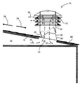
An adjustable passive roof vent according to an embodiment of the present
invention is shown generally with reference numeral 10 in Fig. 1. As shown,
the
adjustable passive vent 10 is installed over an opening 12 in a roof portion
14
of a building enclosure 16, such as an attic for example. As discussed in more
detail below, the adjustable passive roof vent 10 is adjustable for mounting
on
roof portions 14 with different slopes, and configured to vent the enclosure
16
CA 02792461 2012-10-15
,
,
-7-
by permitting gases to pass into (represented by arrows 18) and out of
(represented by arrows 20) the building enclosure 16 through the opening 12
in the roof portion 14. At the same time the adjustable passive roof vent 10
prevents objects, such as for example, moisture (i.e. rain and snow) and
insects, from passing into the building enclosure 16 through the adjustable
passive roof vent 10.
Preferably, the adjustable passive roof vent 10 will be manufactured from
molded plastic. Moldable plastics are available which provide adequate
performance in the range of weather conditions that a typical adjustable
passive
roof vent 10 must endure. Furthermore, the use of a plastic molding process
allows a high volume of devices to be manufactured at a low per-unit cost.
Thus the preferred plastics are those which can be made to conform to the
shape of a suitable mold. Preferred plastics include PP and PE. Preferred
molding techniques include injection molding, thermoforming, reaction
injection
molding, compression molding, and the like. Nevertheless, it will be
appreciated
that the adjustable passive roof vent 10 need not be composed of molded
plastic, but may be composed of any material which allows the adjustable
passive roof vent 10 to adequately perform its necessary functions. Thus, for
example, the adjustable passive roof vent 10 could be composed of metal.
Referring now to Figs. 2 and 3, the adjustable passive roof vent is shown
adjusted for mounting to a roof portion 14 having a 3/12 (or 14.04 ) slope.
Fig.
4 shows the same adjustable passive roof vent adjusted for mounting to a roof
portion 14 having a 12/12 (or 45 ) slope. The particular embodiment of the
invention shown in the figures has features discussed in more detail below
which require a particular orientation of the adjustable passive roof vent in
relation to the slope of the roof portion 14 to which it will be mounted.
Thus, for
clarity, the term upslope side 22 will be used herein to refer to the side of
the
vent intended to face up the slope (see arrow 24 in Fig. 1) of a sloped roof
1
CA 02792461 2012-10-15
-8-
portion 14, and the term downslope side 26 will be used herein to refer to the
side of the adjustable passive roof vent 10 intended to face down the slope
(see
arrow 28 in Fig. 1) of a sloped roof portion 14.
The adjustable passive roof vent 10 has a vent structure 30 and a base 32
which are pivotally attached together by a pair of pivot joints 34. As
discussed
in more detail below, the vent structure 30 has a collar 36 attached to a vent
body 38, and the base 22 has an aperture 40 surrounded by a wall 42 (as best
seen in Fig. 5).
Preferably, each of the pivot joints 34 is made up of a pivot pin 44 on the
aperture surrounding wall 42 (as best seen in Figs. 5 to 7), and a
corresponding
pivot aperture 46 on the collar 36 (as best seen in Fig. 10). However, it is
also
contemplated that the pivot pin 44 may instead be provided on the collar 36
with
the corresponding pivot aperture 46 being provided on the aperture surrounding
wall 42. Moreover, other forms of pivot joints 34 are comprehended by the
present invention. What is important is that the pivot joints 34 join the
collar 36
to the aperture surrounding wall 42 and define a pivot axis 48 about which the
vent structure 30 pivots along a range of angles relative to the base 32, as
described in detail below.
The vent body 38 includes a cover 50 and at least one gas permeable screen
52. In this example, a plurality of gas permeable screens 52 are positioned on
the vent body 38 between the cover 50 and the collar 36 of the vent structure
30. However more or fewer gas permeable screens 52 are contemplated by the
present invention. Preferably the at least one gas permeable screen 52 is
sized, shaped and positioned on the vent body 38 to prevent objects from
passing through the vent structure 30 and into the aperture 40, while at the
same time allowing gas to flow out of the adjustable passive roof vent 10 to
the
outside. This can be accomplished by using a gas permeable screen 52 that
CA 02792461 2012-10-15
-9-
includes a plurality of air ventilation openings 54. As seen in Fig. 2, for
example, the plurality of air ventilation openings 54 can be defined by a
corresponding plurality of spaced apart slats 56. The slats 56 will preferably
be
spaced closely enough together to prevent objects such as insects from passing
through the gas permeable screen 52, while still allowing adequate air flow
through the gas permeable screen 52.
As shown in Fig. 10, the preferred adjustable passive vent 10 will have a
plurality of screen sections 58 arranged in stacked relation between the cover
50 and the collar 36. Although three such screen sections 58 are shown in Fig.
10, it is contemplated that more or fewer may be used according to
requirements. It has been found that positioning the gas permeable screens 52
outwardly from the collar 36 with the use of screen sections 58 increases the
net free air flow area through the adjustable passive roof vent 10. As best
seen
in Fig. 13, the bottom portions 51 of the screen sections 58 preferably
include
a plurality of drain openings 53 to permit water entering through the gas
permeable screens 52 to drain to outside of the adjustable passive vent 10.
Preferably, the bottom portions 51 of the screen sections 58 are strengthened
with ribs 55.
It will be appreciated that the cover 50, the screen sections 58, and the
collar
36 of the vent structure 30 may be attached together in stacked relation in
any
secure fashion. Conventional stake mounting has been found to be adequate.
Thus, in the preferred embodiment, the cover 50, the screen sections 58, and
collar 36 are attached to each other by means of attachment elements 60 as
best seen in Fig. 10. The attachment elements 60 include attachment
members 62 (as best seen in Fig. 12) and attachment receptacles 64 (as best
seen in Fig. 11). In the preferred embodiment, the cover 50 is attached to an
adjacent screen section 58 with four attachment elements 60. Similarly, each
screen section 58 is attached to an adjacent screen section 58 with four
CA 02792461 2012-10-15
-10-
attachment elements 60. The bottom screen section 58 in the stack is also
attached to the adjacent collar 36 with four attachment elements 60. The
attachment members 62 can be located on the bottoms of the cover 50, and the
screen sections 58, with the attachment receptacles 64 located in positional
agreement on the tops of the screen sections 58 and the collar 36 as shown in
Fig. 10. Alternately, the attachment members 62 can be located on the tops of
the screen sections 58 and the collar 36, with the attachment receptacles 64
in
positional agreement on the bottoms of the cover 50, and the screen sections
58. Other arrangements of attachment members 62 and attachment
receptacles 64 will also be appreciated by persons skilled in the art, all of
which
are contemplated by the present invention. What is important is that the
attachment members 62 and attachment receptacles 64 be sized and shaped
to line up with each other, such that when an attachment member 62 is inserted
into an attachment receptacle 64, the attachment member 62 is gripped within
the attachment receptacle 64.
To achieve a firm grip when attachment members 62 are inserted into
attachment receptacles 64 in the direction of arrow 65, each attachment
receptacle 64 has lips 66 at its opening defining a locking slot 68, as best
seen
in Fig. 11. The lips 66 are deformable outwardly when the attachment member
62 is pressed into the attachment receptacle 64 in the direction of arrow 65,
but
not inwardly, and are biassed to return to a closed position when not being
pressed on. As shown in Fig. 12, each attachment member 62 has a head 70
at its tip, the head 70 being wider than the attachment member 62 at the point
of attachment between the head 70 and the attachment member 62. To attach,
for example, the screen section 58 to the collar 36, the attachment members 62
are lined up with the attachment receptacles 64. The attachment heads 70 of
attachment members 62 are then inserted into the locking slots 68 of
attachment receptacles 64. The lips 66 deform outwardly as the attachment
members 62 are inserted in the direction of arrow 65. Once the heads 70 move
,
CA 02792461 2012-10-15
-11-
past the lips 66 and into the locking slots 68, the lips 66 move back to the
closed position. As the lips 66 are not movable inwardly, the lips 66 hold the
heads 70 in the locking slots 68 of attachment members 62, thus securely
attaching the screen section 58 to the collar 36.
Referring again to Fig. 10, the screen sections 58 are preferably provided
with
at least one precipitation baffle 72 attached to a top wall 74. The
precipitation
baffle 72 is preferably sized, shaped and positioned to interfere with the
entry
of precipitation from the outside into the building enclosure 16 through the
aperture 40, and to permit gas and vapour to flow through the aperture 40 and
to the outside. In the preferred embodiment, one precipitation baffle 72
extends
downwardly from the top wall 74 of each screen section 58 inwardly of the gas
permeable screens 52, and a second precipitation baffle 76 extends upwardly
from the bottom wall 78 of each screen section 58, interiorly of the first
precipitation baffle 72. Preferably, the first precipitation baffle 72 extends
far
enough downward from the top wall 74 so that the lower edge of the first
baffle
72 is lower than the upper edge of the second baffle 76. The first and second
precipitation baffles 72, 76 are separated by an air gap, which creates a
tortuous air flow pathway. The first and second precipitation baffles 72, 76,
in
combination with the at least one gas permeable screen 52, creates an
additional tortuous air flow pathway. The tortuous air flow pathways help
inhibit
moisture from entering the aperture 40, while allowing exhaust air to pass
through to the outside. The first and second precipitation baffles 72, 76 are,
in
the preferred embodiment, sized, shaped and positioned to cause precipitation
entering the adjustable passive roof vent 10 through the gas permeable screen
52 to strike the precipitation baffles 72, 76 and drain outside of the
adjustable
passive roof vent 10. Furthermore, the tortuous pathway and associated
redirections in the direction of airflow of the inflowing air causes a slowing
down
of influent air, allowing precipitation entrained in the air (i.e. snow and
ice) to
drop out of the inflowing air before it reaches the aperture 40, thereby
reducing
1
CA 02792461 2012-10-15
,
-
-12-
entry of moisture into the enclosure, for example, due to high wind speeds
during heavy rainfall.
Referring now to Figs. 5 to 7, the base 32 is preferably of a unitary
construction
and has a lower attachment structure 80 for attaching the base 32 to the roof
portion 14 over the opening 12. The lower attachment structure 80 is in the
form of a thin, flat, wide outer flange 82 for securing the base 32 in fluid
communication with the ventilation passage through the opening 12 in the roof
portion 14. The outer flange 82 preferably includes nailing features 84, such
as
for example holes, markings, or areas of weakness, for allowing nails to be
driven through the nailing features 84 and into the roof portion 14, to secure
the
base 32 to the roof portion 14. The outer flange 82 permits shingles 86 to be
lapped over the lower attachment structure 80, so the adjustable passive roof
vent 10 is readily integrated into a shingled roof portion 14 of the building
enclosure 16 in a waterproof manner.
It will be appreciated that the present invention comprehends various forms of
lower attachment structures 80 other than the outer flange 82 shown for the
preferred embodiment. What is important is that the adjustable passive roof
vent 10 has a lower attachment structure 80 which allows the base 32 to be
secured appropriately in fluid communication with the opening 12 in the roof
portion 14 in order to allow venting to take place. Thus, for example, the
lower
attachment structure 80 may be a different shape than the wide, flat, outer
flange 82 of the preferred embodiment. Also, the lower attachment structure
80 need not necessarily include, for example, the nailing features 84. Rather,
the base 32 may be attached to the roof portion 14 by other suitable means,
such as screws, glue or any other means that results in the base 32 being
appropriately secured in fluid communication with the opening 12 through the
roof portion 14 of the building enclosure 16.
1
CA 02792461 2012-10-15
-13-
The aperture 40 through the lower attachment structure 80 permits gas to pass
in to and out of the opening 12 in the roof portion 14 through the base 32. As
previously mentioned, a wall 42 surrounds the aperture 40. The aperture
surrounding wall 42 includes a pair of opposed curvilinear wall sections 88,
and
a pair of opposed intermediate wall sections 90 which are disposed between
the curvilinear wall sections 88. Preferably, the curvilinear wall sections 88
are
parallel to the pivot axis 48 (see Fig. 5), and radiused relative to the pivot
axis
(see Fig. 6).
With reference to Figs. 2 to 4, the pivot joints 34 are shown positioned at
the
intermediate wall sections 90 of the aperture surrounding wall 42, and the
collar
36 is sized and shaped to overlap portions of the aperture surrounding wall
42.
Furthermore, the configuration of the collar 36 in conjunction with the
configuration of the curvilinear wall sections 88 enables the adjustable
passive
roof vent 10 to maintain a continuous wall between the collar 36 and the
aperture surrounding wall 42 along the range of angles from 75.96 (for a 3/12
slope roof portion) to 45 (fora 12/12 slope roof portion). In other words,
when
the vent structure 30 pivots relative to, for example, the outer flange 82 of
the
base 32 along the range of angles from 75.96 to 45 , the upslope and
downslope edges 92, 94 of collar 36 follow arcs spaced slightly outward from
the curvilinear wall sections 88 of the aperture surrounding wall 42. This
helps
to eliminate gaps for insects and dirt to accumulate, provides a clean
exterior
look for aesthetic appeal, and maximizes a net free air flow area through the
adjustable passive roof vent 10.
Of course, as shown in Fig. 1, the adjustable passive roof vent 10 defines a
gas
passageway (see arrows 18 and 20) from the at least one gas permeable
screen 58 to the aperture 40 of the base 32 when the vent structure 30 is
adjusted to one or more of the range of angles relative to the base 32, to
permit
the gas to pass in to and out of the building enclosure 16 through the
adjustable
1
CA 02792461 2012-10-15
-14-
passive roof vent 10 when the adjustable passive roof vent 10 is mounted to
the
roof portion 14.
Preferably at least one securement means is provided to secure the vent
structure 30 in one of the range of angles relative to the base 32. One form
of
the securement means includes at least one securement aperture 96 in the
collar 36 which is sized and shaped to permit a screw fastener 97 to pass
therethrough and secure into the aperture surrounding wall 42. An example of
this securement means can be seen in Figs. 2 to 4 which illustrate two such
securement apertures 96 on one intermediate wall section 90 of the collar 36.
A further two securement apertures 96 may also be provided on the opposite
side of the collar 36. However, it is contemplated that fewer or more
securement apertures 96 may be provided on any portion of the collar 36 that
overlaps with the aperture surrounding wall 42 along the range of angles.
A second form of the securement means includes at least one friction coupling
98 between the collar 36 and the aperture surrounding wall 42 for securing the
vent structure 30 in at least one of the range of angles relative to the base
32.
An example of this securement means can be seen in Fig. 2 which illustrates
two such friction couplings 98 between the collar 36 and aperture surrounding
wall 42 on the same side as the curvilinear wall section 88 at the downslope
side 26. However, it is contemplated that fewer or more friction couplings 98
may be provided between any portions of the collar 36 and aperture
surrounding wall 42 that overlap along the range of angles.
The preferred friction couplings 98 will now be described in more detail with
reference to Figs. 6, 7, and 8. Beginning with Figs. 6 and 7 depicting the
base
32, the curvilinear wall section 88 at the downslope side 26 of the aperture
surrounding wall 42 is shown with a plurality of ramp-shaped coupling
projections 100 extending therefrom. Fig. 8 depicting the vent structure 30
CA 02792461 2012-10-15
-15-
shows a pair of corresponding coupling apertures 102 on the collar 36 in
positional agreement with a pair of respective rows of a plurality of coupling
projections 100 on the aperture surrounding wall 42. However, it is also
contemplated that the coupling projections 100 may have other shapes and that
the coupling apertures 102 may be replaced with functionally equivalent
features such as coupling voids or depressions (not shown). What is important
is that at least one coupling projection 100 is provided on the aperture
surrounding wall 42 to engage a corresponding feature in positional agreement
on the collar 36 for securing the vent structure 30 in at least one of the
range
of angles relative to the base 32. However, it is contemplated that more than
one friction coupling 98 may be provided between any portion of the collar 36
and aperture surrounding wall 42 that overlap along the range of angles.
For example, as best seen in Figs. 6 and 7 the preferred embodiment of the
invention includes twelve coupling projections 100 arranged in two rows on the
curvilinear wall section 88 at the down slope side 26. Fig. 8 shows a pair of
the
corresponding coupling apertures 102 for forming two friction couplings 98
when the vent structure 30 is at one of the range of angles relative to the
base
32. In this example, the coupling projections 100 are configured to form
friction
couplings 98 with the coupling apertures 102 when the vent structure 30 is
pivoted to each of the following angles relative to the outer flange 82 of the
base 32: 75.96 (for a 3/12 slope roof portion), 71.570 (for a 4/12 slope roof
portion), 67.38 (for a 5/12 slope roof portion), 63.43 (for a 6/12 slope
roof
portion), 56.31 (for a 8/12 slope roof portion), and 45 (for a 12/12 slope
roof
portion). Of course other arrangements of the coupling projections 100 and
coupling apertures 102 are possible, as will now be appreciated by the person
skilled in the art.
Preferably the securement by the friction couplings 98 is releasable, and a
lever
arm 104 is provided in association with the coupling aperture 102 to
facilitate
CA 02792461 2012-10-15
-16-
decoupling the coupling aperture 102 from the coupling projection 100. The
lever arm 104 is configured and arranged relative to the coupling aperture 102
to assist a user in deforming the shape of the coupling aperture 102 to allow
the
coupling aperture to be moved apart from the coupling projection 100 thereby
decoupling the friction coupling 98.
Although the preferred embodiment of the present invention includes both the
securement apertures 96 and friction couplings 98, it is contemplated that
other
embodiments may include only one form of securement means.
Referring back to Fig. 6, the preferred adjustable passive roof vent 10
includes
at least one but more preferably two limit stops 106, 108 for limiting both
ends
of the range of angles. In Fig. 6, the first and second limit stops 106, 108
are
shown as projections extending from the aperture surrounding wall 42
configured to limit the range of angles between which the vent structure 30
can
pivot relative to, for example, outer flange 82 of the base 32, in this case
to
between 90 and 45 . As best seen in Fig. 4, each limit stop projection 106,
108 presents an edge portion 110, 112 configured to contact a corresponding
edge 114 of the collar 36 thereby preventing further pivoting of the vent
structure 30 relative to the base 36. The edge portions 110, 112 of the
preferred limit stops 106, 108 are linear. In Fig. 4, one linear limit stop
projection 106 is positioned substantially 45 to the base to limit one end of
the
range of angles to 45 , which is evidenced by the fact that the vent structure
30
is oriented at a 45 angle relative to the outer flange 82 of the base 32. The
other limit stop projection 108 is positioned substantially parallel to the
base 32
to limit other end of the range of angles to 90 relative to the outer flange
82 of
the base 32. In Fig. 9, the vent structure 30 is shown oriented perpendicular
to
the outer flange 82 of the base 32 at the second limit stop 108. It is
contemplated that in the case of the preferred embodiment of the present
invention shown in Fig. 9, the limit stop 108 for limiting the one end of the
range
CA 02792461 2012-10-15
-17-
of angles to 900 relative to the outer flange 82 of the base 32 will only be
used
for packaging the adjustable passive roof vent 10.
In a preferred embodiment of the invention, the base 32 also includes a raised
rain ridge 116 along both sides, as best seen in Fig. 5. The purpose of the
rain
ridge 116 is to direct water toward the portion of the adjustable passive roof
vent 10 disposed downwardly along the sloped roof portion 14. Since the
downwardly disposed portion of the outer flange 82 is lapped over the shingles
86, the water is discharged off of the outer flange 82 on top of the shingles
86,
thus preventing water from entering underneath the shingles 86.
In a preferred embodiment, the rain ridges 116 are molded onto the outer
flange 82 during manufacturing. However, it will be appreciated by those
skilled
in the art that other means of forming a raised edge will provide this
function.
For example, the lateral edges of outer flange 82 can be bent over to form an
edge channel that causes any water migrating sideways to be funnelled
downwardly along the side edge and out onto the top of the shingles 86 below
the adjustable passive roof vent 10.
Preferably, the base 32 also includes a liquid deflector 118. As best seen in
Fig. 9, the liquid deflector 118 is positioned on the aperture surrounding
wall 42
at the upslope side 22 of the adjustable passive roof vent 10. The liquid
deflector 118 provides additional protection against liquid, such as rain,
flowing
down the sloped roof portion 14 from entering the adjustable passive roof vent
10 and into the aperture 40, by guiding the liquid to the sides of the
aperture
surrounding wall 42. Thus, the preferred adjustable passive roof vent 10 will
be
used on sloped roof portions 14 and will be installed with the liquid
deflector
118, positioned on the upslope side 22 of the lower attachment structure 80
for
facing up the slope of the roof portion 14 when mounted to the roof portion
14.
It will be appreciated by those skilled in the art that the present invention
CA 02792461 2012-10-15
-18-
comprehends adjustable passive roof vents 10 in which the adjustable passive
roof vent 10 does not include the liquid deflector 118 described above.
Furthermore, although the preferred liquid deflector 118 has a chevron shape
as shown in Fig. 9, other shapes are contemplated. For example, a smoothly
curved shape could be used in place of the chevron shape. It has been found
that a smoothly curved continuous shape of the liquid deflector 118
facilitates
the cutting of shingles to match its shape, by permitting a single continuous
cut,
as opposed to the two or more cuts required with, for example a chevron-
shaped liquid deflector 118, such as, for example, those formed from two
surfaces meeting at a peak or edge. This prevents damaging overcuts in
shingles during installation, and reduces the risk of future leaks.
It has also been found that under certain conditions, water from rain, snow
melt
or other sources can be driven by strong winds up the slope of the roof under
the bottom of the outer flange 82 of the base 32 of the adjustable passive
roof
vent 10 to the point that it reaches the opening 12 in the roof portion 14 and
drips into the building enclosure 16. To help prevent this path of water
entry,
the preferred adjustable passive roof vent 10 includes a water deflector ridge
120 positioned on the underside of the base 32 as best seen in Fig. 5. The
water deflector ridge 120 is raised from the bottom surface of the outer
flange
82 by about 0.020 inches and positioned between the edge of the downslope
side 26 of the adjustable passive roof vent 10 and the aperture 40 to abut the
surface of the roof portion 14 when installed thereon. According to the
preferred embodiment of the present invention the water deflector ridge 120
has
a chevron-shape as shown in Fig. 5. However, it is also contemplated that the
water deflector ridge 120 may have other shapes and still achieve the desired
results. For example, the water deflector ridge 120 may have a curved shape.
What is important is that the water deflector ridge 120 directs any water
forced
under the outer flange 82 to proceed up the slope of the roof between the roof
portion 14 and the bottom surface of the outer flange 82 in directions away
from
CA 02792461 2012-10-15
-19-
the opening 12 in the roof portion 14. For example, the chevron-shaped water
deflector ridge 120 in Fig. 5 directs the water up the slope of the roof at
angles
away from the opening 12. The deflected water will then drain downwardly
along the slope of the roof portion 14 on top of the shingles 86.
Referring now to Figs. 13 and 14, there is shown another embodiment of the
present invention, which includes a pair of screw fastener retainers 122
attached to one side of the cover 50 of the adjustable passive roof vent 10.
Another pair of screw fastener retainers 122 is attached to the other side of
the
cover 50 in a similar manner. The preferred screw fastener retainers 122 have
four flexible fingers that are sized, shaped and positioned to grip the body
of the
screw fastener 97 after it has been pushed through. The screw fastener
retainers 122 are attached to the cover 50 with frangible portions, such as
lines
of weakness or perforations, to permit an installer in the field to easily cut
or
tear the screw fastener retainers 122 from the cover 50 without damaging the
cover 50. The screw fastener retainers 122 are designed to hold, during for
example packaging and shipping, the screw fasteners 97 which will be used in
conjunction with the securement apertures 96 and aperture surrounding wall 42
to secure the vent structure 30 in at least one of the range of angles
relative to
the base 32. After the installer collects the screw fasteners 97 from the
screw
fastener retainers 122, the screw fastener retainers 122 are no longer needed
and may be removed from the cover 50. Most preferably, the screw fastener
retainers 122 are round so that they may be used by the installer as washers
under the heads of the screw fasteners 97 when the collar 36 is being attached
to the base 32, as discussed in more detail below. It will be appreciated that
each screw fastener retainer 122 may be provided with fewer or more fingers,
or instead of fingers a hole, a weakened area, a dimple, or a marking through
which a screw fastener 97 can be pressed or screwed and then held in the
screw fastener retainer 122. Furthermore, the screw fastener retainers 122 can
be removably attached to any part(s) of the vent structure 30 or base 32, by
CA 02792461 2012-10-15
-20-
molding or other means, which will allow the screw fastener retainers 122 to
hold screw fasteners 97 therein, and permit the installer to remove the screw
fasteners 97 and detach the screw fastener retainers 122 from the part(s).
What is important is that when it is desired to provide a screw fastener
retainer
122 on the adjustable passive roof vent 10, the screw fastener retainers are
capable of holding the screw fasteners and can be detached from the vent
structure 30 or the base 32 by tearing or cutting, without damaging the vent
structure 30 or the base 32 from which they are detached.
Having described an embodiment of the present invention, a method of
installing the present invention can now be described with reference to Fig.
1.
First the installer will determine an appropriate location on a roof portion
14 of
the building enclosure 16 for installing the adjustable passive roof vent 10.
Next
the installer will determine the slope of the roof portion 14. Then the
installer
will adjust the adjustable passive roof vent 10 in accordance with the
determined slope. For example, if the slope of the roof portion 14 is
determined
to be 3/12 (i.e. 14.04 ), the installer will pivot the vent structure 30
relative to the
base 32 until the desired angle is achieved. According to the preferred
embodiment, the adjustable passive roof vent 10 will have friction couplings
98
permitting adjustment of the adjustable passive roof vent 10 appropriate for
one
or more of the more common roof slopes. As mentioned above, the preferred
adjustable passive roof vent 10 will have friction couplings 98 permitting
securement when the vent structure 30 is pivoted to each of the following
angles relative to, for example, the outer flange 82 of the base 32: 75.96
(for
a 3/12 slope roof portion), 71.57 (for a 4/12 slope roof portion), 67.38
(for a
5/12 slope roof portion), 63.43 (for a 6/12 slope roof portion), 56.31 (for
a 8/12
slope roof portion), and 45 (for a 12/12 slope roof portion). The installer
next
drives screw fasteners 97 through one or more securement apertures 96 on the
collar 36 into the aperture surrounding wall 42.
CA 02792461 2012-10-15
,
-21-
ln embodiments of the adjustable passive roof vent 10 which include screw
fastener retainers 122 holding the screw fasteners 97, the installer will
collect
the screw fasteners 97 from the screw fastener retainers 122, and tear or cut
the screw fastener retainers 122 from the vent structure 30 or the base 32
(i.e.
the cover 50 in the case of the embodiment in Figs. 13 and 14). The installer
will then use the screw fasteners 97 as mentioned above, except that the
detached screw fastener retainers 122 may be used as washers under the
heads of the screw fasteners 97.
The installer then cuts out an opening 12 in the roof portion 14, and
carefully
aligns the base 32 of the adjustable passive roof vent 10 over the opening 12,
with the upslope side 22 facing up the slope of the roof portion 14, and the
downslope side 26 facing down the slope of the roof portion 14.
The outer flange 82 is secured in place to permit the vent structure 30 to
cover
the opening 12 in the building enclosure 16. The outer flange 82 is installed
at
the same time as the roofing material is covered with weather protection, such
as shingles 86. Shingles 86 are laid by starting at a low point on any surface
to be protected. Then, course after course the shingles 86 are laid with the
bottom of each next higher course covering the top of the course below. In
this
way, rain water and the like is always kept away from the underlying roofing
material because for any water to get onto the same would require that the
water run uphill to get over the top of the shingle course.
When encountering opening 12 in the roof portion 14, the typical procedure is
to lay the course of shingles 86 up to the bottom of the opening 12, and then
to interleave the outer flange 82 of the base 32 of the adjustable passive
roof
vent 10 in with the shingle courses. In this way the outer flange 82 at the
downslope side 26 will overlie the top edge of the shingle courses 86 below it
to cause water to be shed off the roof. Furthermore, the water deflector ridge
1
CA 02792461 2012-10-15
,
-22-
120 contacts the shingles 86 to help prevent water entry driven by strong
winds
up the slope of the roof as discussed above. At the upslope side 22 the outer
flange 82 will underlie the bottom edge of the shingle course 86 above it.
The outer flange 82 is nailed to the roof material through nailing features 84
in
the conventional manner as the shingles 86 are lapped over the outer flange
82. The shingle nails will be underneath the next overlapping shingles to
prevent leaks as is conventional for such shingles.
Although the above describes adjusting the adjustable passive roof vent 10
before securing it in place to cover the opening 12 in the building enclosure
16,
it is also contemplated that the installer may adjust the adjustable passive
roof
vent 10 in accordance with the determined slope, after it is secured in place
to
the roof.
The aperture 40 in base 32 is sized and shaped to be placed in registry with
the
opening 12 formed in the roofing material. Of course it is not required that
the
aperture 40 and opening 12 be exactly the same size, but the aperture 40 is
necessary to permit the flow of air from one to the other in the usual manner.
While reference has been made to various preferred embodiments of the
invention other variations, implementations, modifications, alterations and
embodiments are comprehended by the broad scope of the appended claims.
Some of these have been discussed in detail in this specification and others
will
be apparent to those skilled in the art. Those of ordinary skill in the art
having
access to the teachings herein will recognize these additional variations,
implementations, modifications, alterations and embodiments, all of which are
within the scope of the present invention, which invention is limited only by
the
appended claims.
1