Note: Descriptions are shown in the official language in which they were submitted.
CA 02792535 2014-08-13
DESCRIPTION
TITLE OF INVENTION: HIGH-STRENGTH HOT-ROLLED STEEL
SHEET AND METHOD OF MANUFACTURING THE SAME
TECHNICAL FIELD
[0001] The present invention relates to a high-
strength hot-rolled steel sheet that achieves
improvement of formability and a fracture property and
a method of manufacturing the same.
This application is based upon and claims the
benefit of priority of the prior Japanese Patent
Application No. 2010-053787 filed on March 10, 2010,
and the prior Japanese Patent Application No. 2010-
053774 filed on March 10, 2010.
BACKGROUND ART
[0002] Conventionally, with the aim of reduction in
weight of a steel sheet, an attempt to increase
strength of a steel sheet has been promoted.
Generally, the increase in strength of a steel sheet
causes deterioration of formability such as bore
expandability. Therefore, it is important how a steel
sheet excellent in balance between tensile strength and
bore expandability is obtained.
[0003] For example, in Patent Literature 1, there has
been disclosed a technique aiming to obtain a steel
sheet excellent in balance between tensile strength and
bore expandability by optimizing a fraction of
microstructure such as ferrite and
- 1 -
CA 02792535 2012-09-07
bainite in steel and precipitates in a ferrite
structure. In Patent Literature 1, it has been
described that the tensile strength of 780 MPa or
more and a bore expansion ratio of 60% or more are
obtained.
[0004] However, in recent years, a steel sheet more
excellent in the balance between the tensile strength
and the bore expandability has been required. For
example, a steel sheet used for an underbody member
of an automobile or the like has been required to
have the tensile strength of 780 MPa or more and the
bore expansion ratio of 70% or more.
[0005] Further, the bore expansion ratio is likely
to vary relatively. Therefore, for improving the
bore expandability, it is important to decrease not
only an average Aave of the bore expansion ratio but
also a standard deviation o of the bore expansion
ratio being an index indicating the variations.
Then, in the steel sheet used for an underbody member
of an automobile or the like as described above, the
average Aave of the bore expansion ratio has been
required to be 80% or more, and the standard
deviation o has been required to be 15% or less and
has been further required to be 10% or less.
[0006] However, conventionally, it has been
difficult to satisfy these requirements.
[0007] Further, in a case when an automobile drives
over a curb or the like to thereby apply a strong
impact load to its underbody part, ductile fracture
- 2 -
CA 02792535 2012-09-07
is likely to occur starting from a punched face of
the underbody part.
Particularly, as a steel sheet
has higher strength, its notch sensitivity is higher,
and thus the fracture from a punched edge face is
more strongly concerned. Thus, as a steel sheet has
higher strength, it is important to prevent the
ductile fracture as described above.
Therefore, in
the steel sheet used as a structure member such as
the underbody part as above, it is also important to
improve the fracture property.
CITATION LIST
PATENT LITERATURE
[0008] Patent Literature 1: Japanese Laid-open
Patent Publication No. 2004-339606
Patent Literature 2: Japanese Laid-open Patent
Publication No. 2010-90476
Patent Literature 3: Japanese Laid-open Patent
Publication No. 2007-277661
SUMMARY OF INVENTION
TECHNICAL PROBLEM
[0009] The present invention has an object to
provide a high-strength hot-rolled steel sheet
allowing bore expandability and a fracture property
to be improved and a method of manufacturing the
same.
SOLUTION TO PROBLEM
[0010] The gist of the present invention is as
follows.
[0011] According to a first aspect of the present
- 3 -
CA 02792535 2012-09-07
invention, a high-strength hot-rolled steel sheet
contains:
in mass%,
C: 0.02% to 0.1%;
Si: 0.001% to 3.0%;
Mn: 0.5% to 3.0%;
P: 0.1% or less;
S: 0.01% or less;
Al: 0.001% to 2.0%;
N: 0.02% or less;
Ti: 0.03% to 0.3%; and
Nb: 0.001% to 0.06%,
the steel sheet further containing at least one
element selected from the group consisting of:
Cu: 0.001 to 1.0%;
Cr: 0.001 to 1.0%;
Mo: 0.001 to 1.0%;
Ni: 0.001 to 1.0%; and
/: 0.01 to 0.2%,
the balance being composed of Fe and inevitable
impurities,
a parameter Q expressed by Mathematical
expression 1 below being 30.0 or more,
a microstructure being made of a ferrite
structure, a bainite structure, or a structure mixed
with the ferrite structure and the bainite structure,
an average grain size of grains included in the
microstructure being 6 pm or less,
an X-ray random intensity ratio of {211} plane on
- 4 -
CA 02792535 2012-09-07
a rolled surface being 2.4 or less, and
on a cross section with a sheet width direction
set as a normal line,
with regard to inclusions having a major
diameter of 3.0 pm or more, a maximum of a major
diameter/minor diameter ratio expressed by (a major
diameter of the inclusion)/(a minor diameter of the
inclusion) being 8.0 or less,
a sum total of a rolling direction length
per 1 mm2 cross section of a predetermined inclusion
group composed of plural inclusions each having a
major diameter of 3.0 pm or more and a predetermined
extended inclusion having a length in a rolling
direction of 30 pm or more being 0.25 mm or less,
the plural inclusions composing the
predetermined inclusion group congregating in both
the rolling direction and a direction perpendicular
to the rolling direction 50 pm or less apart from
each other, and
the predetermined extended inclusion being
spaced over 50 pm apart from all the inclusions each
having a major diameter of 3.0 pm or more in at least
either the rolling direction or the direction
perpendicular to the rolling direction.
[0012] [Mathematical expression 1]
[Ti] Ý[S]
... (Mathematical expression 1)
48 32
([Ti] indicates the Ti content (mass%) and [S]
indicates the S content (mass%).)
- 5 -
CA 02792535 2012-09-07
[0013] According to a second aspect of the present
invention, a high-strength hot-rolled steel sheet
contains:
in mass%,
C: 0.02% to 0.1%;
Si: 0.001% to 3.0%;
Mn: 0.5% to 3.0%;
P: 0.1% or less;
S: 0.01% or less;
Al: 0.001% to 2.0%
N: 0.02% or less;
Ti: 0.03% to 0.3%;
Nb: 0.001% to 0.06%;
REM: 0.0001% to 0.02%; and
Ca: 0.0001% to 0.02%,
the steel sheet further containing at least one
element selected from the group consisting of:
Cu: 0.001 to 1.0%;
Cr: 0.001 to 1.0%;
Mo: 0.001 to 1.0%;
Ni: 0.001 to 1.0%; and
/: 0.01 to 0.2%, and
the balance being composed of Fe and inevitable
impurities,
a parameter Q' expressed by Mathematical
expression 1' below being 30.0 or more,
a microstructure being made of a ferrite
structure, a bainite structure, or a structure mixed
with the ferrite structure and the bainite structure,
- 6 -
CA 02792535 2012-09-07
an average grain size of grains included in the
microstructure being 6 pm or less,
an X-ray random intensity ratio of {211} plane on
a rolled surface being 2.4 or less, and
on a cross section with a sheet width direction
set as a normal line,
with regard to an inclusion having a major
diameter of 3.0 pm or more, a maximum of a major
diameter/minor diameter ratio expressed by (a major
diameter of the inclusion)/(a minor diameter of the
inclusion) being 8.0 or less,
a sum total of a rolling direction length
per 1 mm2 cross section of a predetermined inclusion
group composed of plural inclusions each having a
major diameter of 3.0 pm or more and a predetermined
extended inclusion having a length in a rolling
direction of 30 pm or more being 0.25 mm or less,
the plural inclusions composing the
predetermined inclusion group congregating in both
the rolling direction and a direction perpendicular
to the rolling direction 50 pm or less apart from
each other, and
the predetermined extended inclusion being
spaced over 50 pm apart from all the inclusions each
having a major diameter of 3.0 pm or more in at least
either the rolling direction or the direction
perpendicular to the rolling direction.
[0014] [Mathematical expression 2]
- 7 -
CA 02792535 2012-09-07
/LS1 /LS] + [REM] /[51}
X 15Ø.. (Mathematical
48 32 4032 140 /32
expression 1')
([Ti] indicates the Ti content (mass%), [S] indicates
the S content (mass%), [Ca] indicates the Ca content
(mass%), and [REM] indicates the REM content
(mass%).)
[0015] According to a third aspect of the present
invention, in the high-strength hot-rolled steel
sheet according to the second aspect,
Mathematical expression 2 below is satisfied, and
the maximum of the major diameter/minor diameter
ratio is 3.0 or less,
0.3 ([REM]/140)/([Ca]/40) ...(Mathematical
expression 2).
[0016] According to a fourth aspect of the present
invention, the high-strength hot-rolled steel sheet
according to any one of the first to third aspects,
further contains, in mass%, B: 0.0001% to 0.005%.
[0017] According to a fifth aspect of the present
invention, in the high-strength hot-rolled steel
sheet according to the fourth aspect,
a total grain boundary number density of solid
solution C and solid solution B exceeds 4.5 /nm2 and
is 12 /nm2 or less, and
a size of cementite precipitated in grain
boundaries is 2 pm or less.
[0018] According to a sixth aspect of the present
invention, a method of manufacturing a high-strength
- 8 -
CA 02792535 2012-09-07
hot-rolled steel sheet includes:
rough-rolling a steel slab after heating the
steel slab,
the steel slab containing:
in mass%,
C: 0.02% to 0.1%;
Si: 0.001% to 3.0%;
Mn: 0.5% to 3.0%;
P: 0.1% or less;
S: 0.01% or less;
Al: 0.001% to 2.0%;
N: 0.02% or less;
Ti: 0.03% to 0.3%; and
Nb: 0.001% to 0.06%,
the steel slab further containing at least
one element selected from the group consisting of:
Cu: 0.001 to 1.0%;
Cr: 0.001 to 1.0%;
Mo: 0.001 to 1.0%;
Ni: 0.001 to 1.0%; and
V: 0.01 to 0.2%,
the balance being composed of Fe and
inevitable impurities,
the parameter Q expressed by the
Mathematical expression 1 being 30.0 or more, and
the rough-rolling being performed under a
condition in which an accumulated reduction ratio in
a temperature zone exceeding 1150 C becomes 70% or
less and an accumulated reduction ratio in a
- 9 -
CA 02792535 2012-09-07
temperature zone of 1150 C or lower becomes not less
than 10% nor more than 25%;
subsequently, finish-rolling the steel slab under
a condition in which a beginning temperature is 1050 C
or higher and a finishing temperature is not lower
than Ar3 + 130 C nor higher than Ar3 + 230 C;
subsequently, cooling the steel slab at a cooling
rate of 15 C/sec or more; and
subsequently, coiling the steel slab at 640 C or
lower.
[0019] According to a seventh aspect of the present
invention, a method of manufacturing a high-strength
hot-rolled steel sheet includes:
rough-rolling a steel slab after heating the
steel slab,
the steel slab containing:
in mass%,
C: 0.02% to 0.1%;
Si: 0.001% to 3.0%;
Mn: 0.5% to 3.0%;
P: 0.1% or less;
S: 0.01% or less;
Al: 0.001% to 2.0%;
N: 0.02% or less;
Ti: 0.03% to 0.3%;
Nb: 0.001% to 0.06%;
REM: 0.0001% to 0.02%; and
Ca: 0.0001% to 0.02%, and further
the steel slab further containing at least
- 10 -
CA 02792535 2012-09-07
one element selected from the group consisting of:
Cu: 0.001 to 1.0%;
Cr: 0.001 to 1.0%;
Mo: 0.001 to 1.0%;
Ni: 0.001 to 1.0%, and
V: 0.01 to 0.2%; and
the balance being composed of Fe and
inevitable impurities,
the parameter Q' expressed by the
Mathematical expression l' being 30.0 or more, and
the rough-rolling being performed under a
condition in which an accumulated reduction ratio in
a temperature zone exceeding 1150 C becomes 70% or
less and an accumulated reduction ratio in a
temperature zone of 1150 C or lower becomes not less
than 10% nor more than 25%;
subsequently, finish-rolling the steel slab under
a condition in which a beginning temperature is 1050 C
or higher and a finishing temperature is not lower
than Ar3 + 130 C nor higher than Ar3 + 230 C;
subsequently, cooling the steel slab at a cooling
rate of 15 C/sec or more; and
subsequently, coiling the steel slab at 640 C or
lower.
[0020] According to an eighth aspect of the present
invention, in the method of manufacturing a high-
strength hot-rolled steel sheet according to the
seventh aspect, the steel slab satisfies the
Mathematical expression 2.
- 11 -
CA 02792535 2012-09-07
[0021] According to a ninth aspect of the present
invention, in the method of manufacturing a high-
strength hot-rolled steel sheet according to any one
of the sixth to eighth aspects, the steel slab
further contains, in mass%, B: 0.0001% to 0.005%.
ADVANTAGEOUS EFFECTS OF INVENTION
[0022] According to the present invention, the
composition, the microstructure, and so on are
appropriate, so that it is possible to improve the
bore expandability and the fracture property.
BRIEF DESCRIPTION OF DRAWINGS
[0023] [Fig. 1A] Fig. 1A is a schematic view
depicting peeling;
[Fig. 1B] Fig. 1B is a view showing a photograph
of peeling;
[Fig. 1C] Fig. 1C is a view showing a photograph
of peeling similarly;
[Fig. 2A] Fig. 2A is a view depicting a method of
a notched three-point bending test;
[Fig. 2B] Fig. 2B is a view depicting a notched
test piece;
[Fig. 2C] Fig. 2C is a view depicting a notched
test piece after being forcedly fractured;
[Fig. 3A] Fig. 3A is a view depicting a load
displacement curve;
[Fig. 3B] Fig. 3B is a view indicating a crack
occurrence resistance value Jc and a crack
propagation resistance value T. M.;
[Fig. 4A] Fig. 4A is a view depicting an example
- 12 -
CA 02792535 2012-09-07
of an inclusion group;
[Fig. 4B] Fig. 4B is a view depicting an example
of an extended inclusion;
[Fig. 4C] Fig. 4C is a view depicting another
example of the inclusion group;
[Fig. 4D] Fig. 4D is a view depicting still
another example of the inclusion group;
[Fig. 4E] Fig. 4E is a view depicting another
example of the extended inclusion;
[Fig. 5A] Fig. 5A is a view depicting a
relationship between a sum total M of a rolling
direction length of an inclusion, a maximum of a
major diameter/minor diameter ratio of an inclusion,
and an average .1\ave of a bore expansion ratio;
[Fig. 5B] Fig. 5B is a view depicting the
relationship between a sum total M of a rolling
direction length of an inclusion, a maximum of a
major diameter/minor diameter ratio of an inclusion,
and an average 2,ave of a bore expansion ratio
similarly;
[Fig. 6A] Fig. 6A is a view depicting a
relationship between a sum total M of a rolling
direction length of an inclusion, a maximum of a
major diameter/minor diameter ratio of an inclusion,
and a standard deviation o of a bore expansion ratio;
[Fig. 6B] Fig. 6B is a view depicting the
relationship between a sum total M of a rolling
direction length of an inclusion, a maximum of a
major diameter/minor diameter ratio of an inclusion,
- 13 -
CA 02792535 2012-09-07
and a standard deviation o of a bore expansion ratio
similarly;
[Fig. 7] Fig. 7 is a view depicting a
relationship between a sum total M of a rolling
direction length of an inclusion and a crack
propagation resistance value T. M.;
[Fig. 8] Fig. 8 is a view depicting a
relationship between a numerical value of a parameter
Q' and a sum total M of a rolling direction length of
an inclusion;
[Fig. 9A] Fig. 9A is a view depicting an example
of a relationship of a sum total M of a rolling
direction length of an inclusion with respect to an
accumulated reduction ratio of rough-rolling in a
temperature zone exceeding 1150 C;
[Fig. 9B] Fig. 9B is a view depicting an example
of a relationship of a maximum of a major
diameter/minor diameter ratio of an inclusion with
respect to an accumulated reduction ratio of rough-
rolling in a temperature zone exceeding 1150 C;
[Fig. 9C] Fig. 90 is a view depicting an example
of a relationship of a {211} plane intensity with
respect to an accumulated reduction ratio in a
temperature zone of 1150 C or lower;
[Fig. 90] Fig. 90 is a view depicting an example
of a relationship of a an average grain size of a
microstructure with respect to an accumulated
reduction ratio in a temperature zone of 1150 C or
lower;
- 14 -
CA 02792535 2012-09-07
[Fig. 10A] Fig. 10A is a view depicting another
example of the relationship of a sum total M of a
rolling direction length of an inclusion with respect
to an accumulated reduction ratio of rough-rolling in
a temperature zone exceeding 1150 C;
[Fig. 10B] Fig. 10B is a view depicting another
example of the relationship of a maximum of a major
diameter/minor diameter ratio of an inclusion with
respect to an accumulated reduction ratio of rough-
rolling in a temperature zone exceeding 1150 C;
[Fig. 10C] Fig. 10C is a view depicting another
example of the relationship of a {211} plane
intensity with respect to an accumulated reduction
ratio in a temperature zone of 1150 C or lower;
[Fig. 10D] Fig. 10D is a view depicting another
example of the relationship of an average grain size
of a microstructure with respect to an accumulated
reduction ratio in a temperature zone of 1150 C or
lower;
[Fig. 11A] Fig. 11A is a view depicting an
example of the existence or absence of peeling in a
relationship between a total grain boundary number
density of solid solution C and solid solution B and
a coiling temperature;
[Fig. 11B] Fig. 11B is a view depicting another
example of the existence or absence of peeling in a
relationship between a total grain boundary number
density of solid solution C and solid solution B and
a coiling temperature;
- 15 -
CA 02792535 2012-09-07
[Fig. 12A] Fig. 12A is a view depicting an
example of a relationship between a size of grain
boundary cementite and a bore expansion ratio;
[Fig. 12B] Fig. 12B is a view depicting another
example of the relationship between a size of grain
boundary cementite and a bore expansion ratio;
[Fig. 13A] Fig. 13A is a view depicting an
example of a relationship between a coiling
temperature and a size of grain boundary cementite;
and
[Fig. 13B] Fig. 13B is a view depicting another
example of the relationship between a coiling
temperature and a size of grain boundary cementite.
DESCRIPTION OF EMBODIMENTS
[0024] Hereinafter, embodiments of the present
invention will be explained.
[0025] First, fundamental research leading to the
completion of the present invention will be
explained.
[0026] The present inventors conducted the following
investigations in order to examine predominant causes
with respect to a bore expandability and a fracture
property of a steel sheet having a ferrite structure
and a bainite structure as a main phase.
[0027] The present inventors performed hot rolling,
cooling, coiling, and so on under the conditions as
listed in Table 5 and Table 9 that will be described
later, on sample steels of steel compositions 1A1 to
1W3 and 2A1 to 2W3 as listed in Table 4 and Table 8
- 16 -
CA 02792535 2012-09-07
that will be described later to thereby manufacture
hot-rolled steel sheets each having a thickness of
2.9 mm.
[0028] Then, a tensile strength, a bore
expandability such as an average Xave and a standard
deviation o of a bore expansion ratio, and a fracture
property were measured on the obtained hot-rolled
steel sheets. Further, a microstructure, a texture,
and inclusions were examined on the obtained hot-
rolled steel sheets.
[0029] Further, an n value (a work hardening
coefficient) and resistance to peeling were also
examined on the obtained hot-rolled steel sheets.
Here, the peeling will be explained. When punching
of the steel sheet is performed, as depicted in Fig.
1A to Fig. 10, a punched edge face 4 including a
shear face 2 and a fractured face 3, and a shear
droop 1 occur. Further, on the shear face 2 and/or
the fractured face 3, a flaw or minute crack 5 is
sometimes formed. Such a flaw or minute crack 5
occurs so as to get into the inside of the steel
sheet from the edge face in parallel with the surface
of the steel sheet. Further, the plurality of the
flaw or minute crack 5 is sometimes formed in the
sheet thickness direction. Here, the flaw and minute
crack is generically called peeling. The peeling
tends to occur regardless of whether the bore
expandability is good or bad, and when the peeling
exists, there is sometimes a case that the crack
- 17 -
CA 02792535 2012-09-07
,
extends starting from the peeling to cause a fatigue
failure.
[0030] In the evaluation of the tensile strength,
from a 1/2 sheet width portion of each of the sample
steels, a No. 5 test piece described in JIS Z 2201
was made so as to make the longitudinal direction of
the test piece parallel with the sheet width
direction. Then, a tensile test was performed based
on the method described in JIS Z 2241 to measure the
tensile strength from each of the obtained test
pieces. Further, based on each of measured values by
the tensile test, a true stress and a true strain
were calculated, and based on the calculated true
stress and true strain, the n value (work hardening
coefficient) was obtained.
[0031] In the evaluation of the bore expandability,
a test piece having a length in the rolling direction
of 150 mm and a length in the sheet width direction
of 150 mm was made from a 1/2 sheet width portion of
each of the sample steels. Then, based on the method
described in JFS T 1001-1996 of the Japan Iron and
Steel Federation Standard, a bore expansion test was
performed to measure the bore expansion ratio of each
of the test pieces. In the evaluation of the bore
expandability, the plural test pieces, for example,
the 20 test pieces were made from the single sample
steel, and the bore expansion ratios of the
respective test pieces were arithmetically averaged
to calculate the average Aave of the bore expansion
- 18 -
CA 02792535 2012-09-07
ratio and to calculate also the standard deviation o
of the bore expansion ratio. When N pieces of the
test pieces are made from the single sample steel,
the standard deviation o is expressed by Mathematical
expression 3 below.
[0032] [Mathematical expression 3]
lx,n
62 ¨ ( ¨ a, ave)2 . . . (Mathematical expression
1,1
3)
(Ai indicates the bore expansion ratio of the i-th
piece out of the plurality of test pieces.)
[0033] In the bore expansion test, a punching punch
having a diameter of 10 mm was used. Further, a
punching clearance obtained by dividing a clearance
between the punching punch and a die bore by the
thickness of the test piece was set to 12.5%, and a
punched bore having an initial bore diameter (DO) of
mm was provided in the test piece. Then, a
conical punch having a vertex angle of 60 was pressed
into the punched bore from the same direction as that
of the punching, and an inside diameter of the bore
Df at the time when a crack formed on a punched edge
face penetrated in the sheet thickness direction was
measured. The bore expansion ratio was obtained by
Mathematical expression 4 below. Here, the
penetration, of the crack, in the sheet thickness
direction was confirmed visually.
A (%) = [(Df - DO)/DO] x 100 ...Mathematical
expression 4
- 19 -
CA 02792535 2012-09-07
[0034] In the evaluation of the resistance to the
peeling, based on the above-described method
described in JFS T 1001-1996 of the Japan Iron and
Steel Federation Standard, punching was performed
with respect to a single test piece to visually
observe a punched edge face of the test piece. The
clearance in performing the punching was set to 25%
in consideration of variation of the punching
condition. Further, the diameter of a punched bore
was set to 10 mm. When an area where the peeling
occurred on the circumference of the edge face ranged
for 20 degrees or more when seen from the center of
the circle in terms of an angle, "occurrence" was
set, and when the area ranged from over 0 degree to
less than 20 degrees in terms of an angle, "slight
occurrence" was set, and when no peeling occurred,
"none" was set. Here, the "occurrence" practically
becomes a problem, but the "slight occurrence" is
within an allowable range practically.
[0035] The fracture property was evaluated by a
crack occurrence resistance value Jc (J/m2) and a
crack propagation resistance value T. M. (tearing
modulus) (J/m3) obtained by a notched three-point
bending test, and a fracture appearance transition
temperature ( C) and Charpy absorbed energy (J)
obtained by a Charpy impact test. The crack
occurrence resistance value Jc indicates resistance
to occurrence of a crack from a steel sheet forming a
structure member when an impact load is applied
- 20 -
CA 02792535 2012-09-07
thereto (start of fracture), and the crack
propagation resistance value T. M. indicates
resistance to large-scale fracture of a steel sheet
forming a structure member. It is important to
improve the above values so as not to jeopardize the
safety of the structure member when an impact load is
applied thereto. However, there has not been
proposed a technique aiming at improving the crack
occurrence resistance value Jc and the crack
propagation resistance value T. M. conventionally.
[0036] In the
notched three-point bending test, five
or more notched test pieces 11 each having a notch 12
provided therein as depicted in Fig. 2A and Fig. 2B
were made from the single sample steel so as to make
the longitudinal direction of the test piece parallel
with the sheet width direction. Here, a depth a of
the notch 12 was set to 2.6 mm and a width of the
notch 12 was set to 0.1 mm.
Further, a dimension, of
the notched test piece 11, in the rolling direction
was set to 5.2 mm and a thickness B was set to 2.6
mm. Then,
as depicted in Fig. 2A, both end portions,
of the notched test piece 11, in the longitudinal
direction were each set to a supporting point 13, and
a middle portion of the notched test piece 11 was set
to a loading point 14, and under the condition that a
displacement amount of the loading point (stroke) was
changed variously, the notched three-point bending
test was performed with respect to the notched test
piece 11. The diameter of the supporting point 13
- 21 -
CA 02792535 2012-09-07
was set to 5 mm and a spacing between the supporting
points 13 was set to 20.8 mm. Thereafter, a heat
treatment in which the notched test piece 11 was
maintained at 250 C for 30 minutes in the atmosphere
and then was air-cooled was performed with respect to
the notched test piece 11 having had the notched
three-point bending test performed thereon, and
thereby on a fracture 16 formed by the notched three-
point bending test, oxidation coloring was performed.
Subsequently, the notched test piece 11 was cooled
down to a liquid nitrogen temperature with liquid
nitrogen, and then at the temperature, the notched
test piece 11 was forcedly fractured so that a crack
might extend in the notch depth direction from the
notch 12 in the notched test piece 11. As depicted
in Fig. 2C, a fracture 17 formed by the notched
three-point bending test was made clearly visible by
the oxidation coloring and was positioned between a
notch surface 16 and a fracture 18 formed by the
forced fracture. Then, the fracture 17 formed by the
notched three-point bending test was observed after
the forced fracture, and based on Mathematical
expression 5 below, a crack extension La (m) was
obtained.
La = (L1 + L2 + L3)/3 ...Mathematical expression
[0037] Fig.
3A is a load displacement curve obtained
by a notched three-point bending test performed under
a predetermined stroke condition. A work energy A
- 22 -
CA 02792535 2012-09-07
(J) corresponding to the energy applied to the test
piece on the test was obtained based on the load
displacement curve, and a parameter J (J/m2) was
obtained based on Mathematical expression 6 below
with the work energy A, the thickness B (m) of the
test piece, and a ligament b (m). The ligament b
here means the length in the notch depth direction of
the portion other than the notch in the cross section
including the notch 12 in the notched test piece 11.
J = 2 x the work energy A/{the thickness B x the
ligament b} ...Mathematical expression 6
[0038] Further, as depicted in Fig. 3B, the
relationship between the crack extension La (m) of
the notched test piece 11 and the parameter J (J/m2)
was expressed in a graph. Then, a vertical axis
value (the value of the parameter J) of an
intersection point of a line La having an inclination
of "3 x (YP + TS)/2" and passing through the origin
and a primary regression line Lb with respect to the
crack extension La and the parameter J was obtained,
and the value was set to be the crack occurrence
resistance value Jc (J/m2) being a value indicating
the resistance to the crack occurrence of the sample
steel. Further, the inclination of the primary
regression line Lb was also obtained and was set to
be the crack propagation resistance value T. M. (J/m3)
indicating the resistance to the crack propagation of
the sample steel. The crack occurrence resistance
value Jc is a value corresponding to the work energy
- 23 -
CA 02792535 2012-09-07
per unit area necessary for making a crack occur, and
indicates resistance to occurrence of a crack from a
steel sheet forming a structure member when an impact
load is applied thereto (start of fracture). The
crack propagation resistance value T. M. is a value
to be an index indicating the degree of the work
energy necessary for extending the crack, and
indicates resistance to large-scale fracture of a
steel sheet forming a structure member.
[0039] In the Charpy impact test, a V-notch test
piece described in JIS Z2242 was made from each of
the sample steels so as to make the longitudinal
direction of the test piece parallel with the sheet
width direction. Then, the test was performed with
respect to the V-notch test piece based on the method
described in JIS Z2242. The test piece was set to be
a subsize test piece having a thickness of 2.5 mm.
The fracture appearance transition temperature and
the Charpy absorbed energy were obtained based on JIS
Z2242. Then, the fracture appearance transition
temperature at which the percentage ductile fracture
becomes 50%, and the Charpy absorbed energy obtained
at a test temperature set to room temperature (23 C
C) were used for the evaluation.
[0040] In the examination of the microstructure and
inclusions, a 1/4 sheet width position of each of the
steel sheets was observed. In the observation, a
sample was cut out so that a cross section with the
sheet width direction set as a normal line, (which
- 24 -
CA 02792535 2012-09-07
will be called an L cross section, hereinafter),
might be exposed, and the cross section was polished
and thereafter the cross section was corroded with a
nital reagent. Then, by using an optical microscope,
the observation was performed at 200-fold to 500-fold
magnification. Further, in the examination of the
microstructure, by a method similar to the above
method, corrosion was performed with a correction
repeller solution, and island-shaped martensite was
observed.
[0041] In the examination of the texture, an X-ray
random intensity ratio was measured. The X-ray
random intensity ratio here means a numerical value
obtained in a manner that X-ray diffraction intensity
of a standard sample having no integration in a
particular orientation and having random orientation
distribution and X-ray diffraction intensity of the
sample steel to be measured are measured by X-ray
diffraction measurement, and the obtained X-ray
diffraction intensity of the sample steel is divided
by the X-ray diffraction intensity of the standard
sample. It means that as the X-ray random intensity
ratio in a particular orientation is larger, the
amount of the texture having a crystal plane in the
particular orientation is large in the steel sheet.
[0042] The X-ray diffraction measurement was
performed by using a diffractometer method using an
appropriate X-ray tube, or the like. In making a
sample for the X-ray diffraction measurement, a test
- 25 -
CA 02792535 2012-09-07
piece was cut out from a 1/2 sheet width position of
the steel sheet in size of 20 mm in the sheet width
direction and 20 mm in the rolling direction, and by
mechanical polishing, the sample was polished to a
1/2 sheet thickness position in the sheet thickness
direction, and then strain was removed by
electrolytic polishing or the like. Then, the X-ray
diffraction measurement of the 1/2 sheet thickness
position of the obtained sample was performed.
[0043] It has been known that an average grain size
of the microstructure has an effect on the fracture
appearance transition temperature. Thus, when
examining the microstructure, the average grain size
of the microstructure was measured. In the
measurement of the average grain size, first, in a
portion of the middle of the sheet thickness of the L
cross section at the 1/4 sheet width position of the
steel sheet to be measured, being 500 pm in the sheet
thickness direction and 500 pm in the rolling
direction, crystal orientation distribution of the
portion was examined with a step of 2 pm by an EBSD
method. Next, points having an orientation
difference of 15 or more were connected by a line
segment, and the line segment was regarded as a grain
boundary. Then, a number average of circle
equivalent diameters of grains surrounded by the
grain boundary was obtained to be set as the average
grain size.
[0044] Further, in the examination of the
- 26 -
CA 02792535 2012-09-07
inclusions, based on the following idea, a sum total
M of a rolling direction length of the inclusion
(mm/mm2) to be defined as will be described later was
measured.
[0045] The inclusion forms voids in the steel during
deformation of the steel sheet and promotes the
ductile fracture to cause the deterioration of the
bore expandability. Further, as the shape of the
inclusion is a shape extended longer in the rolling
direction, stress concentration in the vicinity of
the inclusion is increased, and in accordance with
the phenomenon, the effect of which the inclusion
deteriorates the bore expandability is increased.
Conventionally, it has been known that the larger the
rolling direction length of the single inclusion is,
the greater the bore expandability is deteriorated.
[0046] The present inventors found that similarly to
the single extended inclusion, an inclusion group
made of an inclusion group composed in a manner that
the extended inclusion and the spherical inclusion
are distributed in the rolling direction being the
crack propagation direction within a predetermined
spacing range also affects the deterioration of the
bore expandability. This is conceivably because by
the synergistic effect of strain to be introduced
into the vicinity of each of the inclusions composing
the inclusion group during deformation of the steel
sheet, the large stress concentration occurs in the
vicinity of the inclusion group. It was found that
- 27 -
CA 02792535 2012-09-07
quantitatively, the inclusion group made of a group
of the inclusions aligned 50 pm or less apart from
the adjacent different inclusion on a line in the
rolling direction affects the bore expandability
equally to the single inclusion extended to the
length nearly equal to the rolling direction length
of the inclusion group. The line in the rolling
direction here means a virtual line extended in the
rolling direction.
[0047] Thus, in order to evaluate the bore
expandability, the inclusion having a shape as
explained below and positioned as explained below was
set to an object to be measured.
[0048] First, the inclusion to be measured was
limited only to ones each having a major diameter of
3.0 pm or more. This is conceivably because the
effect of the inclusion having a major diameter of
less than 3.0 pm on the deterioration of the bore
expandability is small. Further, the major diameter
here means the longest diameter in a cross sectional
shape of the inclusion to be observed, and is a
diameter in the rolling direction in many cases.
[0049] Then, a group of the inclusions aligned 50 pm
or less apart from the adjacent different inclusion
on the line in the rolling direction was regarded as
a single inclusion group and a rolling direction
length Ll of the inclusion group was measured, and
the inclusion group having the rolling direction
length Ll of 30 pm or more was set to an object to be
- 28 -
CA 02792535 2012-09-07
evaluated. That is, in the case when the plural
inclusions are aligned on the line in the rolling
direction, if the two inclusions 50 pm or less apart
from each other in the rolling direction exist, these
are set to be contained in the single inclusion
group, and further, if the different inclusion 50 pm
or less apart from at least one of these two
inclusions exits, this inclusion is also set to be
contained in the inclusion group. Then, in the
present invention, the inclusion group is defined by
repetition of the positional relationship between
such inclusions with each other. The number of
inclusions contained in the inclusion group is only
necessary to be two or more. For example, as
depicted in Fig. 4A, it is set that five inclusions
21a to 21e each having a major diameter of 3.0 pm or
more are aligned on the line in the rolling
direction. Further, it is set that a spacing X
between the inclusion 21a and the inclusion 21b
exceeds 50 pm, the spacing X between the inclusion
21b and the inclusion 21c is 50 pm or less, the
spacing X between the inclusion 21c and the inclusion
21d is 50 pm or less, and the spacing X between the
inclusion 21d and the inclusion 21e exceeds 50 pm.
In this case, a group of the inclusions 21b to 21d is
regarded as one inclusion group, and if the rolling
direction length Ll of the inclusion group is 30 pm
or more, the inclusion group is set to an object to
be evaluated.
- 29 -
CA 02792535 2012-09-07
[0050] Further, even though an inclusion spaced over
50 pm apart from the adjacent different inclusion on
the line in the rolling direction existed, a rolling
direction length L2 of the inclusion was measured and
the inclusion having the rolling direction length L2
of 30 pm or more was set to an object to be
evaluated. For example, as depicted in Fig. 4B, it
is set that three inclusions 21f to 21h each having a
major diameter of 3.0 pm or more are aligned on the
line in the rolling direction. Further, it is set
that the spacing X between the inclusion 21f and the
inclusion 21g exceeds 50 pm, and the spacing X
between the inclusion 21g and the inclusion 21h
exceeds 50 pm. Further, it is set that the rolling
direction length L2 of each of the inclusion 21f and
the inclusion 21h is less than 30 pm, and the rolling
direction length L2 of the inclusion 21g is 30 pm or
more. In this case, the inclusion 21g is set to an
object to be evaluated. It should be noted that, in
a case when another inclusion exists 50 pm or less
apart in the direction perpendicular to the rolling
direction as will be described later, it is set that
with the another inclusion, the inclusion group is
composed.
[0051] Incidentally, the reason why the object to be
measured was limited to the inclusion group having
the rolling direction length L1 of 30 pm or more and
the inclusion having the rolling direction length L2
of 30 pm or more is conceivably because the effect of
- 30 -
CA 02792535 2012-09-07
,
the inclusion group having the rolling direction
length L1 of less than 30 pm and the inclusion having
the rolling direction length L2 of less than 30 pm on
the deterioration of the bore expandability is small.
[0052] As is clear from the above-described
explanation, even though the inclusion having the
rolling direction length of 30 pm or more exists, if
the inclusion exists 50 pm or less apart from the
adjacent different inclusion on the line in the
rolling direction, the inclusion is part of an
inclusion group. For example, as depicted in Fig.
40, it is set that four inclusions 21i to 211 each
having a major diameter of 3.0 pm or more are aligned
on the line in the rolling direction.
Further, it is
set that the spacing X between the inclusion 21i and
the inclusion 21j exceeds 50 pm, the spacing X
between the inclusion 21j and the inclusion 21k is 50
pm or less, and the spacing X between the inclusion
21k and the inclusion 211 exceeds 50 pm.
Further, it
is set that the rolling direction length L2 of each
of the inclusions 21i, 21k, and 211 is less than 30
pm, and the rolling direction length L2 of the
inclusion 21j is 30 pm or more. In this case, a
group of the inclusions 21j and 21k is regarded as
one inclusion group, and this inclusion group is set
to an object to be evaluated. Hereinafter, the
inclusion that is not contained in any one of the
inclusion groups and has the rolling direction length
L2 of 30 pm or more is sometimes called the "extended
- 31 -
CA 02792535 2012-09-07
inclusion."
[0053] Further,
even if between the two inclusions
that do not exist on a line in the rolling direction
strictly and each have a major diameter of 3.0 pm or
more, a spacing in the direction perpendicular to the
rolling direction is 50 pm or less, the large stress
concentration sometimes occurs in the vicinity of
these inclusions. Thus, even though a group of the
plural inclusions that are not aligned on the line in
the rolling direction exists, if a spacing in the
rolling direction between the inclusions and a
spacing in the direction perpendicular to the rolling
direction between the inclusions are each 50 pm or
less, the inclusions are regarded to compose one
inclusion group.
[0054] For example, as depicted in Fig. 4D, it is
set that six inclusions 21m to 21r each having a
major diameter of 3.0 pm or more are dispersed in the
steel sheet. Further,
it is set that the spacing X
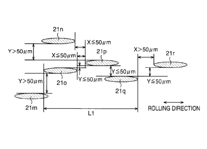
in the rolling direction between the inclusion 210
and the inclusion 21p and a spacing Y in the
direction perpendicular to the rolling direction
between the inclusion 210 and the inclusion 21p are
each 50 pm or less, and the spacing X in the rolling
direction between the inclusion 21p and the inclusion
21q and the sOacing Y in the direction perpendicular
to the rolling direction between the inclusion 21p
and the inclusion 21q are each 50 pm or less.
Further, it is set that the spacing Y in the
- 32 -
CA 02792535 2012-09-07
direction perpendicular to the rolling direction
between the inclusion 21m and the inclusion 210
exceeds 50 pm, the spacing Y in the direction
perpendicular to the rolling direction between the
inclusion 21n and the inclusion 21p exceeds 50 pm,
and the spacing X in the rolling direction between
the inclusion 21q and the inclusion 21r exceeds 50
pm. In this case, a group of the inclusions 210 to
21q is regarded as one inclusion group, and if the
rolling direction length L1 of this inclusion group
is 30 pm or more, this inclusion group is set to an
object to be evaluated.
[0055] Further, for example, as depicted in Fig. 4E,
it is set that four inclusions 21s to 21v each having
a major diameter of 3.0 pm or more are dispersed in
the steel sheet. Further, it is set that the spacing
X in the rolling direction between the inclusion 21s
and the inclusion 21u and the spacing Y in the
direction perpendicular to the rolling direction
between the inclusion 21s and the inclusion 21u each
exceed 50 pm, the spacing Y in the direction
perpendicular to the rolling direction between the
inclusion 21t and the inclusion 21u exceeds 50 pm,
and the spacing X in the rolling direction between
the inclusion 21v and the inclusion 21u exceeds 50
pm. Further, it is set that the rolling direction
length L2 of the inclusion 21u is 30 pm or more. In
this case, the inclusion 21u is regarded as one
extended inclusion to be set to an object to be
- 33 -
CA 02792535 2012-09-07
,
evaluated.
However, if the spacing X in the rolling
direction between the inclusion 21t and the inclusion
21u and the spacing Y in the direction perpendicular
to the rolling direction between the inclusion 21t
and the inclusion 21u are each 50 pm or less, even in
a case when they are not aligned on the line in the
rolling direction, a group of the inclusion 21t and
the inclusion 21u is regarded as one inclusion group.
[0056]
In the evaluation of the bore expandability,
first, the rolling direction length L1 of all the
inclusion groups observed in a single visual field,
and the rolling direction length L2 of all the
extended inclusions observed in the same visual field
were measured and a sum total L (mm) of the rolling
direction lengths L1 and L2 was obtained. Next, a
numerical value M (mm/mm2) was obtained with the
obtained sum total L based on Mathematical expression
7 below, and the obtained numerical value M was
defined as the sum total M of the rolling direction
length of the inclusion group and the extended
inclusion per unit area (1 mm2) (hereinafter, the sum
total M of the rolling direction length of the
inclusion group and the extended inclusion is
sometimes called the the sum total M of the rolling
direction length of the inclusion."). Then, the
relation between this sum total M and the bore
expandability was examined. Note that S in
Mathematical expression 7 is an area of the observed
visual field (mm2).
- 34 -
CA 02792535 2012-09-07
M = L/S ...Mathematical expression 7
[0057] Here,
the reason why from the sum total L of
the rolling direction length of the inclusion group
and the extended inclusion, not the average of the
rolling direction length but the sum total M per unit
area was obtained is because of the following reason.
[0058] It is
conceivable that during deformation of
a steel sheet, when the number of inclusion groups
and extended inclusions (inclusion group and so on)
is small, the crack propagates in a manner that voids
generated around these inclusion group and so on are
not connected, but when the number of inclusion group
and so on is large, voids around the inclusion group
and so on are connected continuously to form a long
continuous void, and thereby the ductile fracture is
promoted. Such an effect of the number of the
inclusion group and so on cannot be indicated by the
average of the rolling direction length of the
inclusion group and so on, but can be indicated by
the sum total M per unit area. From
such a point of
view, the sum total M per unit area of the rolling
direction length of the inclusion group and so on was
obtained.
[0059] Then, details will be described later, but
according to the test conducted by the present
inventors, with regard to the inclusion group and the
extended inclusion each having the length in the
rolling direction of 30 pm or more, a clear
correlation existed between the sum total M of the
- 35 -
CA 02792535 2012-09-07
rolling direction length of the inclusion and the
average Aave of the bore expansion ratio. On the
other hand, with regard to the inclusion group and
the extended inclusion each having the length in the
rolling direction of 30 pm or more, a significant
correlation was not seen between the average of the
rolling direction length of the inclusion group and
so on and the average Aave of the bore expansion
ratio. That is, it turned out that it is difficult
to indicate the degree of the bore expandability by
the average of the rolling direction length of the
inclusion group and so on.
[0060]
Further, during deformation of a steel sheet,
in a portion of the stress being concentrated by the
deformation, the crack occurs and propagation of the
crack occurs starting from the inclusion group and
the extended inclusion. In a
case when the sum total
M of the rolling direction length of the inclusion is
large, in particular, the above tendency becomes
strong, and thus the crack occurrence resistance
value Jc and the crack propagation resistance value
T. M. are decreased. Further, the Charpy absorbed
energy being the energy required for the fracture of
the test piece in a temperature zone where the
ductile fracture occurs is an index affected by both
of the crack occurrence resistance value Jc and the
crack propagation resistance value T. M..
Therefore,
in a case when the sum total M of the rolling
direction length of the inclusion is large, the crack
- 36 -
CA 02792535 2014-08-13
occurrence resistance value Jc and the crack
propagation resistance value T. M. are decreased, and
the Charpy absorbed energy is also decreased.
[0061] From such a point of view, in the fundamental
research, the bore expandability and the fracture
property were evaluated by using the sum total M of the
rolling direction length of the inclusion, the average
Aave of the bore expansion ratio, the crack occurrence
resistance value Jc, the crack propagation resistance
value T. M., the Charpy absorbed energy, and so on.
[0062] Further, in the examination of an inclusion, as
for each of the inclusions in a visual field, a major
diameter/minor diameter ratio of the inclusion
expressed by a major diameter of the inclusion/a minor
diameter of the inclusion was measured, and the maximum
out of the major diameter/minor diameter ratios of the
inclusions in the visual field was identified. This is
because even in a case of the sum total M of the
rolling direction length of the inclusion being equal,
when the shape of each of the inclusions is circle and
the major diameter/minor diameter ratio is small, the
stress concentration in the vicinity of the inclusion
is decreased during deformation of the steel sheet, and
the average Aave of the bore expansion ratio, the crack
occurrence resistance value Jc, and the Charpy absorbed
energy are made better. Further, by the experiment, it
was found that a correlation exists between the maximum
- 37 -
CA 02792535 2012-09-07
of the major diameter/minor diameter ratio of the
inclusion and the standard deviation o of the bore
expansion ratio, and thus also from the point of view
of evaluating the standard deviation o of the bore
expansion ratio, the maximum of the major
diameter/minor diameter ratio of the inclusion was
measured.
[0063] The steel sheet obtained under the hot
rolling conditions as described above was one of
which the tensile strength is distributed in a range
of 780 to 830 MPa and the microstructure is the
ferrite structure or the bainite structure as a main
phase.
[0064] Fig. 5A and Fig. 5B are views each depicting
the relationship between the sum total M of the
rolling direction length of the inclusion, the
maximum of the major diameter/minor diameter ratio of
the inclusion, and the average Aave of the bore
expansion ratio. Fig. 6A and Fig. 6B are views each
depicting the relationship between the sum total M of
the rolling direction length of the inclusion, the
maximum of the major diameter/minor diameter ratio of
the inclusion, and the standard deviation o of the
bore expansion ratio. Fig. 7
is a view depicting the
relationship between the sum total M of the rolling
direction length of the inclusion and the crack
propagation resistance value T. M.. Fig.
5A and Fig.
6A each depict the relationship of the case of using
the steel compositions 1A1 to 1W3 listed in Table 4,
- 38 -
CA 02792535 2012-09-07
and Fig. 5B and Fig. 6B each depict the relationship
of the case of using the steel compositions 2A1 to
2W3 listed in Table 8. Fig. 7 depicts the
relationship in the case of using a steel containing,
in mass%, C: 0.03% to 0.04%, Si: 0.01% to 1.05%, Mn:
0.7% to 1.9%, P: 0.0008% to 0.01%, S: 0.001% to
0.005%, Al: 0.02% to 0.04%, Ti: 0.12% to 0.18%, REM:
0% to 0.004%, Ca: 0% to 0.004%, Nb: 0% to 0.04%, and
V: 0% to 0.02%, and the balance being composed of Fe
and inevitable impurities.
[0065] It is found that as depicted in Fig. 5A and
Fig. 5B, the average Aave of the bore expansion ratio
of the steel sheet is better as the sum total M of
the rolling direction length of the inclusion is
smaller and the maximum of the major diameter/minor
diameter ratio is smaller.
Further, it is found that
as depicted in Fig. 6A and Fig. 6B, the standard
deviation o of the bore expansion ratio is better as
the maximum of the major diameter/minor diameter
ratio of the inclusion is smaller.
Incidentally, the
experimental results depicted in Fig. 5A, Fig. 5B,
Fig. 6A, and Fig. 6B satisfy the conditions of the
hot-rolled steel sheet according to the present
invention in terms of the X-ray random intensity
ratio of the {211} plane (which is also called the
{211} plane intensity, hereinafter), and so on,
except the condition regarding the sum total M of the
rolling direction length of the inclusion and the
condition regarding the maximum of the major
- 39 -
CA 02792535 2012-09-07
diameter/minor diameter ratio.
[0066] It is found from Fig. 5A, Fig. 5B, Fig. 6A,
and Fig. 6B that, when the sum total M of the rolling
direction length of the inclusion is 0.25 mm/mm2 or
less and the maximum of the major diameter/minor
diameter ratio is 8.0 or less, the average Xave of
the bore expansion ratio can be 80% or more and the
standard deviation o can be 15% or less.
Further, it
is also found that, when the maximum of the major
diameter/minor diameter ratio is 3.0 or less, the
average 2\ave of the bore expansion ratio can be 85%
or more and the standard deviation o can be 10% or
less. Thus, in the present invention, as for the
inclusions each having a major diameter of 3.0 pm or
more, the sum total M of the rolling direction length
of the inclusion is set to 0.25 mm/mm2 or less and the
maximum of the major diameter/minor diameter ratio of
the inclusion is set to 8.0 or less. Further, the
maximum of the major diameter/minor diameter ratio of
the inclusion is preferably set to 3.0 or less.
[0067] Further, it is important to improve the crack
propagation resistance value T. M. in order to
prevent fracture of a steel sheet composing a
structure member. The crack propagation resistance
value T. M., as depicted in Fig. 7, relays on the sum
total M of the rolling direction length of the
inclusion, and it turned out that as the sum total M
of the rolling direction length of the inclusion is
increased, the crack propagation resistance value T.
- 40 -
CA 02792535 2012-09-07
. ,
M. is decreased.
[0068] Further, the present inventors found that the
inclusion group and the extended inclusion are MnS
extended by the rolling and a residue of a
desulfurization material applied for desulfurization
at a steelmaking stage. As described above, the
inclusion group and the extended inclusion increase
the sum total M of the rolling direction length and
the maximum of the major diameter/minor diameter
ratio of the inclusion to cause the deterioration of
the bore expandability, the crack propagation
resistance value T. M., and so on. The present
inventors found that in a case of REM and Ca being
added, the shapes of precipitates such as CaS which
precipitates in a manner not to use oxide or sulfide
of REM as a nucleus and calcium aluminate being a
mixture of CaO and alumina are also extended in the
rolling direction slightly. The present inventors
found that these inclusions also increase the sum
total M of the rolling direction length and the
maximum of the major diameter/minor diameter ratio of
the inclusion to cause the deterioration of the bore
expandability and so on.
[0069] Then, as a result of investigating a
manufacturing method for suppressing these inclusions
in order to achieve the improvement of the bore
expandability, the crack propagation resistance value
T. M., and so on, it turned out that the following
conditions are important.
- 41 -
CA 02792535 2012-09-07
[0070] First,
for suppressing MnS, it is important
to decrease the content of S which bonds to Mn.
Therefore, in the present invention, the S content is
set to 0.01% or less. Further, in the Ti-added
steel, TiS is formed at a temperature higher than a
temperature zone where MnS is formed, so that it is
possible to decrease the content of S which bonds to
Mn. Even in the steel having REM and Ca added
thereto, similarly it is possible to decrease the
content of S which bonds to Mn by precipitating
sulfides of REM and Ca. Thus, for
suppressing MnS,
it is important to contain Ti, REM, and Ca in a
larger proportion than the total content of S
stoichiometrically.
[0071] As a result of examining the relationship
between the numerical value of the parameter Q'
expressed by the Mathematical expression l' and the
sum total M of the rolling direction length of the
inclusion based on such an idea, it turned out that
as depicted in Fig. 8, when the numerical value of
the parameter Q' is 30.0 or more, the sum total M of
0.25 mm/mm2 or less, which is required in the present
invention, can be obtained. Fig. 8 depicts the
relationship in the case of using a steel similar to
that in Fig. 7. Further, it also turned out that,
when the numerical value of the parameter Q' is 30.0
or more, the maximum of the major diameter/minor
diameter ratio of the inclusion of 8.0 or less, which
is required in the present invention, can be
- 42 -
CA 02792535 2012-09-07
=
obtained, though not illustrated. Then, in the
present invention, the value of the parameter Q' is
set to 30.0 or more. Incidentally, in the case when
REM and Ca are not contained in the steel, the
parameter Q expressed by the Mathematical expression
1 may be used in place of the parameter Q'. Here, it
is also conceivable to simply decrease the S content
in order to suppress the content of MnS, but in this
case, a manufacturing load in a desulfurization
process is increased and additionally the
desulfurization material used in the desulfurization
process may remain, and consequently, the content of
the extended inclusions is increased. Therefore, it
is particularly effective to set the numerical value
of the parameter Q' to 30.0 so that the content of
MnS may be suppressed not by decreasing the S content
but by increasing the contents of Ca and REM.
[0072] [Mathematical expression 4]
[Ti]
Q _
... (Mathematical expression 1)
48 32
(2,==
[Ti] Ý[S] + t[Ca] /LS] + [REM] AS])
X 15Ø.. (Mathematical
48 32 40 / 32 140 / 32)
expression 1')
[0073] Further, the present inventors examined the
relationship between the numerical value of
([REM]/140)/([Ca]/40) and the maximum of the major
diameter/minor diameter ratio of the inclusion in
terms of decreasing precipitates such as CaS which
precipitates in a manner not to use oxide or sulfide
- 43 -
CA 02792535 2012-09-07
of REM as a nucleus. As a result, it turned out
that, when the numerical value of
([REM]/140)/([Ca]/40) is 0.3 or more, the maximum of
the major diameter/minor diameter ratio of 3.0 or
less, which is the preferable condition of the
present invention, can be obtained, though not
illustrated. Thus, as
the condition of setting the
maximum of the major diameter/minor diameter ratio of
the inclusion to 3.0 or less, Mathematical expression
8 below is preferably satisfied.
0.3 5. ([REM]/140)/([Ca]/40) ...(Mathematical
expression 8)
[0074] The
reason why, when the numerical value of
([REM]/140)/([Ca]/40) is 0.3 or more, 3.0 or less of
the maximum of the major diameter/minor diameter
ratio can be obtained is conceivably because of the
following reason. In a case when a much larger
amount of REM than Ca is added, CaS and so on
crystallize or precipitate in a manner to use
spherical oxide or sulfide of REM as a nucleus, and
generally spherical precipitates precipitate. On the
other hand, when the proportion of REM to Ca is
decreased, oxide or sulfide of REM to be a nucleus is
decreased, and thus a lot of extended-shaped
precipitates such as CaS precipitate in a manner not
to use oxide or sulfide of REM as a nucleus. Then,
as a result, it is conceivable that the major
diameter/minor diameter ratio of the inclusion is
affected.
- 44 -
CA 02792535 2012-09-07
[0075] Further, in the present invention, for
decreasing calcium aluminate, the Ca content is set
to 0.02% or less.
[0076] Fig. 9A depicts the relationship of the sum
total M of the rolling direction length of the
inclusion with respect to an accumulated reduction
ratio of rough-rolling in a temperature zone
exceeding 1150 C in a sample steel made of a steel
composition a listed in Table 1 below, and Fig. 9B
depicts the relationship of the maximum of the major
diameter/minor diameter ratio with respect to the
accumulated reduction ratio of the rough-rolling in
the temperature zone exceeding 1150 C in the sample
steel made of the steel composition a listed in Table
1 below. Fig. 9C depicts the relationship of the
{211} plane intensity with respect to an accumulated
reduction ratio in a temperature zone of 1150 C or
lower, and Fig. 9D depicts the relationship of the
average grain size of the microstructure with respect
to the accumulated reduction ratio in the temperature
zone of 1150 C or lower. Further, Fig. 10A depicts
the relationship of the sum total M of the rolling
direction length of the inclusion with respect to the
accumulated reduction ratio of the rough-rolling in
the temperature zone exceeding 1150 C in a sample
steel made of a steel composition b listed in Table 2
below, and Fig. 10B depicts the relationship of the
maximum of the major diameter/minor diameter ratio
with respect to the accumulated reduction ratio of
- 45 -
CA 02792535 2012-09-07
4
the rough-rolling in the temperature zone exceeding
1150 C in the sample steel made of the steel
composition b listed in Table 2 below. Fig. 10C
depicts the relationship of the {211} plane intensity
with respect to the accumulated reduction ratio in
the temperature zone of 1150 C or lower, and Fig. 100
depicts the relationship of the average grain size of
the microstructure with respect to the accumulated
reduction ratio in the temperature zone of 1150 C or
lower. The accumulated reduction ratio of the rough-
rolling here means the ratio of which a steel slab is
reduced in each temperature zone based on the
thickness of the steel slab before the rough-rolling.
An accumulated reduction ratio R1 (%) of the rough-
rolling in the temperature zone exceeding 1150 C is
defined by Mathematical expression 9 below.
Further,
an accumulated reduction ratio R2 (%) of the rough-
rolling in the temperature zone of 1150 C or lower is
defined by Mathematical expression 10 below.
Further, here a beginning temperature of finish-
rolling was 1075 C, a finishing temperature of the
finish-rolling was set to 940 C, a cooling rate on a
run-out-table (ROT: run-out-table) was 30 C/second,
and a coiling temperature was 480 C.
[0077] [Mathematical expression 5]
R1= tartbl X100 . . . (Mathematical expression 9)
to
- 46 -
CA 02792535 2014-08-13
R2 a
t 2-tb2
X100. . . (Mathematical expression 10)
to
(to indicates the thickness of the steel slab before the
rough-rolling, tal indicates the thickness of the steel
slab before the first reduction in the temperature zone
exceeding 1150 C, tbi indicates the thickness of the
steel slab before the final reduction in the
temperature zone exceeding 1150 C, ta2 indicates the
thickness of the steel slab before the first reduction
in the temperature zone of 1150 C or lower, and tb2
indicates the thickness of the steel slab before the
final reduction in the temperature zone of 1150 C or
lower.)
[0078] [Table 1]
STEEL CHEMICAL COMPONENT (MASS%)
COMPOSITION C Si Mn P S Al N Nb Ti . REM Ca
a 0.0370.951.2910.0060.0010.0270.00390.040.1380.00100.0015
[0079] [Table 2]
STEEL CHEMICAL COMPOSITION (MASS%)
COMPOSITION C Si Mn P S Al N V Nlo, Ti REM Ca
0.037 0.95 1.29 0.006 0.001 0.027 0.0039 0.05 - 0.138 0.0010 0.0015
The symbol "-" means that the element is not added and
that the content of the element is as low as inevitable
impurities.
[0080] From the above, it is found that in a case of
the accumulated reduction ratio in the temperature zone
exceeding 1150 C being in excess of 70%, the sum total M
of the rolling direction length and the maximum of the
major diameter/minor diameter ratio of
- 47 -
CA 02792535 2012-09-07
,
the inclusion are both increased, thus making it
impossible to obtain the sum total M of 0.25 mm/mm2 or
less and the maximum of the major diameter/minor
diameter ratio of the inclusion of 8.0 or less. This
is conceivably because as the accumulated reduction
ratio of the rough-rolling performed in a high
temperature zone such as the temperature zone
exceeding 1150 C is increased, the inclusions are more
likely to be extended by the rolling.
[0081] Further, it is found that in a case of the
accumulated reduction ratio in the temperature zone
of 1150 C or lower being less than 10%, the average
grain size of the microstructure is increased to
exceed 6 pm. This is conceivably because as the
accumulated reduction ratio of the rough-rolling
performed in a low temperature zone such as the
temperature zone of 1150 C or lower is decreased, the
grain size of austenite after recrystallization is
increased, and thus the average grain size of the
microstructure in a final product is also increased.
[0082] Further, it is found that in a case of the
accumulated reduction ratio in the temperature zone
of 1150 C or lower being in excess of 25%, the {211}
plane intensity is increased to exceed 2.4. This is
conceivably because when the accumulated reduction
ratio of the rough-rolling performed in a relatively
low temperature zone such as the temperature zone of
1150 C or lower is too large, the recrystallization
does not progress substantially completely after the
- 48 -
CA 02792535 2012-09-07
,
rough-rolling, and a non-recrystallized structure to
be the cause of increasing the {211} plane intensity
remains even after the finish-rolling, and
consequently the {211} plane intensity in a final
product is increased.
[0083] Next, another fundamental research leading to
the completion of the present invention will be
explained.
[0084] The present inventors made steel slabs
through melting and casting with compositions listed
in Table 3 to manufacture hot-rolled steel sheets
with the changing finishing temperature of the
finish-rolling and the coiling temperature, which
have a great effect on the materials of the hot-
rolled steel sheet among the manufacturing processes
of the hot-rolled steel sheet. Specifically, hot
rolling was performed on the steel slabs under the
condition of a heating temperature set to 1260 C and
the finishing temperature of the finish-rolling set
to 750 C to 1000 C, and then the steel slabs were
cooled at an average cooling rate of about 40 C/sec
and coiled at a temperature of 0 C to 750 C. Thus,
the hot-rolled steel sheets each having a thickness
of 2.9 mm were manufactured. Then, various
examinations were performed. In the following
examinations, unless otherwise mentioned, samples
each cut out from a 1/4 position of the steel sheet
width (a 1/4 sheet width portion) or a 3/4 position
of the steel sheet width (a 3/4 sheet width portion)
- 49 -
CA 02792535 2014-08-13
were used.
[0085] [Table 3]
TABLE 3
STEEL CHEMICAL COMPONENT (UNIT:MASS%)
COMPOSITION C Si Mn P S Al N Nb Ti
0.083 0.31 1.89 0.011 0.004 0.038 0.0041 0.000 0.000 0.0000
0.040 1.01 1.22 0.012 0.004 0.037 0.0038 0.045 0.142 0.0000
0.042 0.97 1.24 0.011 0.005 0.041 0.0035 0.009 0.140 0.0007
0.047 0.89 1.33 0.013 0.005 0.029 0.0028 0.001 0.118 0.0011
[0086] In Table 3, Ti, Nb, and B are not contained in
a steel composition c, and Ti and Nb are contained but
B is not contained in a steel composition d. Further,
Ti, Nb, and B are contained in a steel composition e,
and Ti, B and a minute amount of Nb are contained in a
steel composition f.
[0087] The present inventors investigated the
condition of suppressing the peeling. By the research
of the present inventors, it has been clarified that
grain boundary number densities of solid solution C and
solid solution B affect the occurrence of the peeling.
Further, it has been found that the coiling temperature
affects the grain boundary number densities of solid
solution C and solid solution B.
[0088] Then, with respect to the obtained hot-rolled
steel sheets, the existence or absence of cracking of a
fractured face in the relationship between the coiling
temperature and a grain boundary segregation density of
solid solution C and solid solution B was examined. In
this examination, the evaluation of the peeling and the
measurement of the grain boundary
- 50 -
CA 02792535 2012-09-07
number densities of solid solution C and solid
solution B were performed in accordance with methods
described below.
[0089] In the evaluation of the peeling, through a
method similar to that described in JFS T 1001-1996
of the Japan Iron and Steel Federation Standard,
punching was performed with the clearance set to 20%,
and the existence or absence of peeling of the
punched face was confirmed visually.
[0090] In the measurement of the grain boundary
number densities of solid solution C and solid
solution B, a three-dimensional atom probe method was
used. A position sensitive atom probe (PoSAP:
position sensitive atom probe) invented by A. Cerezo
et al. at Oxford University in 1988 is an apparatus
in which a position sensitive detector (position
sensitive detector) is incorporated in a detector of
the atom probe and that in analysis, is capable of
simultaneously measuring time of flight and a
position of an atom that has reached the detector
without using an aperture. If the apparatus is used,
it is possible to display all the constituent
elements in alloy existing in the surface of the
sample as a two-dimensional map with atomic-level
spatial resolution. Further, an atomic layer is
evaporated one by one from the surface of the sample
through using an electric field evaporation
phenomenon, and thereby the two-dimensional map can
also be expanded in the depth direction to be
- 51 -
CA 02792535 2012-09-07
displayed and analyzed as a three-dimensional map.
For the observation of a grain boundary, an FB2000A
manufactured by Hitachi, Ltd. was used as a focused
ion beam (FIB) apparatus, and a grain boundary
portion was made to be brought into an acicular tip
portion with an arbitrary-shaped scanning beam in
order to form the cut sample into an acicular shape
by electrolytic polishing. In this
manner, acicular
samples for PoSAP each containing the grain boundary
portion were made. Then, each of the acicular
samples for PoSAP was observed to identify the grain
boundary with the fact that grains different in
orientation exhibit a contrast by a channeling
phenomenon of a scanning ion microscope (SIN), and
was cut with the ion beam. The apparatus used as a
three-dimensional atom probe was an OTAP manufactured
by CAMECA, and as the measurement condition, the
temperature of a sample position was set to about 70
K, a probe total voltage was set to 10 kV to 15 kV,
and a pulse ratio was set to 25%. Then, the grain
boundary and grain interior of each of the samples
were measured three times respectively, and an
average of the measurement was set as a
representative value. In this manner, solid solution
C and solid solution B existing in the grain boundary
and in the grain interior were measured.
[0091] The
value obtained by eliminating background
noise and the like from the measured value was
defined as an atom density per unit area of grain
- 52 -
CA 02792535 2012-09-07
. .
boundary to be set as the grain boundary number
density (/nm2). Thus, solid solution C existing in
the grain boundary is exactly a C atom existing in
the grain boundary, and solid solution B existing in
the grain boundary is exactly a B atom existing in
the grain boundary. The grain boundary number
density is also the grain boundary segregation
density.
[0092] The total grain boundary number density of
solid solution C and solid solution B in the present
invention is the total density per unit area of grain
boundary of solid solution C and solid solution B
existing in the grain boundary. This value is a
value obtained by adding the measured values of solid
solution C and solid solution B.
[0093] The distribution of atoms is found on an atom
map three-dimensionally, so that it can be confirmed
that a large number of C atoms and B atoms are at the
position of the grain boundary.
[0094] Results of such examination are depicted in
Fig. 11A and Fig. 11B. Fig. 11A depicts the
existence or absence of peeling in the relationship
between the total grain boundary number density of
solid solution C and solid solution B and a coiling
temperature (CT) in the steel compositions c, d, and
e. Fig. 11B depicts the existence or absence of
peeling in the relationship between the total grain
boundary number density of solid solution C and solid
solution B and the coiling temperature (CT) in the
- 53 -
CA 02792535 2012-09-07
,
steel compositions c, d, and f. In
Fig. 11A and Fig.
11B, outline marks (0, 0, 0, 4 each indicate that no
peeling has occurred, and black marks (0, t A) each
indicate that slight peeling has occurred.
[0095] It was found from Fig. 11A and Fig. 11B that
in a case of the grain boundary number density of
solid solution C and solid solution B exceeding 4.5
/nm2, the peeling can be suppressed effectively. The
reason why the slight peeling has occurred at 4.5 /nm2
or less is presumed because the strength at the grain
boundary was relatively decreased as compared with
that of the grain interior.
[0096] With regard to the relationship between the
existence or absence of peeling and the coiling
temperature, in the steel composition c not
containing Ti and Nb substantially, the grain
boundary number density of solid solution C and solid
solution B was in excess of 4.5 /nm2 even at any
coiling temperature, and no peeling occurred. In
contrast to this, in the steel compositions d to f
each containing Ti and Nb, when the coiling
temperature was increased, the grain boundary number
density of solid solution C and solid solution B
became 4.5 /nm2 or less, and the peeling occurred.
[0097] This is presumed because, though in the steel
composition c, Ti and Nb were not contained
substantially, so that even though the coiling
temperature was increased, precipitation of TiC and
the like did not occur and the high grain boundary
- 54 -
CA 02792535 2012-09-07
=
number density of solid solution C and solid solution
B was kept, in the steel compositions d to f, when
the coiling temperature was increased, solid solution
C that had segregated in the grain boundary
precipitated in the grain interior as TiC after the
coiling mainly and thus the grain boundary number
density of solid solution C was decreased.
[0098] Further, the reason why in the steel
compositions e and f, the grain boundary number
density exceeding 4.5 /nm2 was obtained up to the
coiling temperature higher than that of the steel
composition d was because B was contained, and thus
even though C precipitated in the grain interior as
TiC, solid solution B segregated in the grain
boundary and thereby the decrease in solid solution C
in the grain boundary was compensated.
[0099] As a result that the present inventors
further conducted various examinations of the
obtained steel sheets in order to find the condition
of further improving the bore expandability, it
turned out that the effect of the size of grain
boundary cementite on the bore expandability is
particularly large. In this examination, similarly
to the above-described method, plural test pieces,
for example, 10 test pieces were made from a single
sample steel, and were each subjected to a bore
expansion test based on the method described in JFS T
1001-1996 of the Japan Iron and Steel Federation
Standard, and the average .1\ave of the bore expansion
- 55 -
CA 02792535 2012-09-07
ratio was calculated. Further, the size of grain
boundary cementite was measured according to a method
described below.
[0100] First, a sample for a transmission electron
microscope was taken from the position of the 1/4
thickness of a sample cut out from a 1/4 sheet width
portion or a 3/4 sheet width portion of the sample
steel. Then, the sample was observed with a
transmission electron microscope having a field
emission gun (FEG) with an acceleration voltage of
200 kV mounted thereon. As a result, analyzing a
diffraction pattern made it possible to confirm that
precipitates observed in grain boundaries is
cementite. Incidentally, in the present invention,
the size of grain boundary cementite is defined as an
average of a circle equivalent size of which all
grain boundary cementite observed in a single visual
field is measured by image processing or the like.
[0101] Fig. 12A depicts the relationship between the
size of grain boundary cementite and the bore
expansion ratio in the steel compositions c, d, and
e. Fig. 12B depicts the relationship between the
size of grain boundary cementite and the bore
expansion ratio in the steel compositions c, d, and
f.
[0102] It is found from Fig. 12A and Fig. 12B that a
correlation exists between the bore expansion ratio
and the size of grain boundary cementite. That is,
it was newly found that as the size of grain boundary
- 56 -
CA 02792535 2012-09-07
,
cementite is smaller, the bore expansion ratio is
improved, and when the size of grain boundary
cementite becomes 2 pm or less, the bore expansion
ratio becomes 80% or more.
[0103] The reason why as the size of cementite
existing in grain boundaries is smaller, the bore
expansion ratio is improved is conceivably because of
the following reason.
[0104] First, it is conceivable that stretch
flanging workability and burring workability typified
by the bore expansion ratio are affected by voids to
be the origin of cracking formed during punching or
shearing. It is conceivable that the voids occur
because in the case when a cementite phase
precipitated in grain boundaries of matrix is large
in some degree with respect to matrix grains, the
matrix grains are subjected to excessive stress in
the vicinity of phase boundaries of the matrix
grains. On the other hand, it is conceivable that in
the a case when the size of grain boundary cementite
is small, cementite is relatively small with respect
to the matrix grains and mechanically, the stress
concentration does not occur and the voids do not
occur easily, and thus the bore expansion ratio is
improved.
[0105] Fig. 13A depicts the relationship between the
coiling temperature and the size of grain boundary
cementite in the steel compositions c, d, and e.
Fig. 13B depicts the relationship between the coiling
- 57 -
CA 02792535 2012-09-07
. .
temperature and the size of grain boundary cementite
in the steel compositions c, d, and f.
[0106] As depicted in Fig. 13A and Fig. 13B, even in
all the steel compositions c to f, as the coiling
temperature is increased, the size of grain boundary
cementite is increased, but the size of grain
boundary cementite tends to be small rapidly when the
coiling temperature becomes a certain temperature or
higher. In the steel compositions d to f each
containing Ti and Nb, in particular, the decrease in
the size of grain boundary cementite was remarkable.
Particularly, in the steel composition e, the size of
grain boundary cementite became 2 pm or less in the
case of the coiling temperature being 480 C or higher,
and in the steel composition f, the size of grain
boundary cementite became 2 pm or less in the case of
the coiling temperature being 560 C or higher. This
is conceivable as follows.
[0107] It has been conceivable that there is a nose
zone in terms of a precipitation temperature of
cementite in an c'-phase.
It has been known that this
nose zone is expressed by a balance between
nucleation with the degree of supersaturation of C in
the a-phase set as a driving force and grain growth
of Fe3C whose rate is determined by diffusion of C and
Fe. When the coiling temperature is lower than the
nose zone, the degree of supersaturation of C is
large and the driving force of the nucleation is
large, but C and Fe can hardly diffuse due to the low
- 58 -
CA 02792535 2012-09-07
temperature and the precipitation of cementite is
suppressed regardless of the grain boundary or grain
interior, and even though cementite precipitates, the
size is small. On the other hand, when the coiling
temperature is higher than the temperature of the
nose zone, solubility of C is increased and the
driving force of the nucleation is decreased, but a
diffusion length is increased, and the density is
decreased, but the size shows a tendency to become
coarse. However, in a case when the elements that
form carbide such as Ti and Nb are contained, a
precipitation nose zone of the elements (Ti, Nb, and
so on) in the a-phase is on the higher temperature
side than that of cementite, and due to precipitation
of carbide, C is depleted. Therefore, a
precipitation amount of cementite and the size of
cementite are decreased. For such a reason, it is
conceivable that in the steel composition e, the size
of grain boundary cementite became 2 pm or less in
the case of the coiling temperature being 480 C or
higher, and in the steel composition f, the size of
grain boundary cementite became 2 pm or less in the
case of the coiling temperature being 560 C or higher.
[0108] The present invention, as described above,
has been made by performing the control of the
inclusions, particularly the content and form of
sulfide, and the control of the microstructure and
the texture, for the purpose of inventing the steel
sheet having the high strength, the high formability,
- 59 -
CA 02792535 2012-09-07
and the high fracture property, in order to
contribute to a reduction in weight of a passenger
vehicle or the like.
[0109] (First embodiment)
Next, there will be explained reasons for
limiting a composition in a high-strength hot-rolled
steel sheet according to a first embodiment of the
present invention. Note that hereinafter, mass% in
the composition is simply described as %.
[0110] C: 0.02% to 0.1%
C is an element which bonds to Nb, Ti, and so on
to contribute to the improvement of the tensile
strength by precipitation strengthening. Also, C
decreases the fracture appearance transition
temperature by making the microstructure fine.
Further, C segregates in the grain boundaries as
solid solution C to thereby have an effect of
suppressing exfoliation of the grain boundaries
during punching to suppress the occurrence of the
peeling. When the C content is less than 0.02%, the
effects cannot be obtained sufficiently, and the
desired bore expandability and fracture property
cannot be obtained. On the other hand, when the C
content exceeds 0.1%, iron carbide (Fe3C), which is
not preferable for the average Aave of the bore
expansion ratio, the crack occurrence resistance
value Jc, and the Charpy absorbed energy, is likely
to be formed excessively. Therefore, the C content
is set to be not less than 0.02% nor more than 0.1%.
- 60 -
CA 02792535 2012-09-07
. .
Further, in order to further improve the above-
described effects of improving the tensile strength
and the like, the C content is preferably 0.03% or
more, and is more preferably 0.04% or more.
Further,
as the C content is decreased, the formation of iron
carbide (Fe3C) is effectively suppressed, and thus in
order to obtain the more excellent average Aave of
the bore expansion ratio, and so on, the C content is
preferably 0.06% or less, and is more preferably
0.05% or less.
[0111] Si: 0.001% to 3.0%
Si is an element necessary for preliminary
deoxidation. When the Si content is less than
0.001%, it is difficult to perform the sufficient
preliminary deoxidation. Also, Si contributes to the
improvement of the tensile strength as a solid
solution strengthening element and suppresses the
formation of iron carbide (Fe3C) to enhance
precipitation of carbide fine precipitates of Nb and
Ti. As a result, the average Aave of the bore
expansion ratio, the crack occurrence resistance
value Jc, and the Charpy absorbed energy are made
better. On the other hand, when the Si content
exceeds 3.0%, the effects are saturated and the
economic efficiency is deteriorated. Therefore, the
Si content is set to be not less than 0.001% nor more
than 3.0%. Further, in order to further improve the
above-described effects of improving the tensile
strength and the like, the Si content is preferably
- 61 -
CA 02792535 2012-09-07
0.5% or more, and is more preferably 1.0% or more.
Further, in consideration of the economic efficiency,
the Si content is preferably 2.0% or less, and is
more preferably 1.3% or less.
[0112] Mn: 0.5% to 3.0%
Mn is an element which contributes to the
improvement of the tensile strength of the steel
sheet as a solid solution strengthening element.
When the Mn content is less than 0.5%, it is
difficult to obtain the sufficient tensile strength.
On the other hand, when the Mn content exceeds 3.0%,
slab cracking during hot rolling occurs easily.
Therefore, the Mn content is set to be not less than
0.5% nor more than 3.0%.
Further, in order to obtain
the higher tensile strength, the Mn content is
preferably 0.75% or more, and is more preferably 1.0%
or more.
Further, in order to more securely suppress
the slab cracking, the Mn content is preferably 2.0%
or less, and is more preferably 1.5% or less.
[0113] P: 0.1% or less (not containing 0%)
P is an impurity to be mixed inevitably, and with
an increase in the content, its segregation amount in
the grain boundaries increases, and P is an element
which causes the deterioration of the average Aave of
the bore expansion ratio, the crack occurrence
resistance value Jc, and the Charpy absorbed energy.
Therefore, the smaller the P content is, the more
desirable it is, and in the case of the P content
being 0.1% or less, these characteristic values of
- 62 -
CA 02792535 2012-09-07
,
the average .Xave of the bore expansion ratio, and so
on fall within allowable ranges. Therefore, the P
content is set to 0.1% or less. Further, in order to
further suppress the deterioration of the properties
caused by the containing of P, the P content is
preferably 0.02% or less, and is more preferably
0.01% or less.
[0114] S: 0.01% or less (not including 0%)
S is an impurity to be mixed inevitably, and when
the S content exceeds 0.01%, MnS is formed in large
amounts in the steel during slab heating to be
extended by hot rolling, and thereby the sum total M
of the rolling direction length of the inclusion and
the major diameter/minor diameter ratio of the
inclusion are increased. As a result, it is not
possible to obtain the desired average 2,ave and
standard deviation o of the bore expansion ratio,
crack occurrence resistance value Jc, crack
propagation resistance value T. M., and Charpy
absorbed energy. Therefore, the S content is set to
0.01% or less. Further, in order to further suppress
the deterioration of the properties caused by the
containing of S, the S content is preferably 0.003%
or less, and is more preferably 0.002% or less. On
the other hand, in the case when the desulfurization
with the desulfurization material is not performed,
it is difficult to set the S content to be less than
0.001%.
[0115] Al: 0.001% to 2.0%
- 63 -
CA 02792535 2012-09-07
Al is an element necessary for deoxidation of the
molten steel. When the Al content is less than
0.001%, it is difficult to deoxidize the molten steel
sufficiently. Also, Al is also an element that
contributes to the improvement of the tensile
strength. On the other hand, when the Al content
exceeds 2.0%, the effects are saturated and the
economic efficiency is deteriorated. Therefore, the
Al content is set to be not less than 0.001% nor more
than 2.0%. Also, in order to make the deoxidation
more secure, the Al content is preferably 0.01% or
more, and is more preferably 0.02% or more.
Further,
in consideration of the economic efficiency, the Al
content is preferably 0.5% or less, and is more
preferably 0.1% or less.
[0116] N: 0.02% or less (not including 0%)
N forms precipitates with Ti and Nb at a higher
temperature than C to decrease Ti and Nb effective
for fixing C. That is, N causes the decrease in the
tensile strength. Thus, the N content has to be
decreased as much as possible, but if the N content
is 0.02% or less, it is allowable. Further, in order
to more effectively suppress the decrease in the
tensile strength, the N content is preferably 0.005%
or less, and is more preferably 0.003% or less.
[0117] Ti: 0.03% to 0.3%
Ti is an element which finely precipitates as TiC
to contribute to the improvement of the tensile
strength of the steel sheet by precipitation
- 64 -
CA 02792535 2012-09-07
strengthening. When the Ti content is less than
0.03%, it is difficult to obtain the sufficient
tensile strength. Further, Ti precipitates as TiS
during slab heating in a hot rolling process to
thereby suppress the precipitation of MnS which forms
the extended inclusion and decrease the sum total M
of the rolling direction length of the inclusion. As
a result, the average Xave of the bore expansion
ratio, the crack occurrence resistance value Jc, the
crack propagation resistance value T. M., and the
Charpy absorbed energy are made better. On the other
hand, when the Ti content exceeds 0.3%, the effects
are saturated the economic efficiency is
deteriorated. Thus, the Ti content is set to be not
less than 0.03% nor more than 0.3%. Also, in order
to obtain the higher tensile strength, the Ti content
is preferably 0.08% or more, and is more preferably
0.12% or more. Further, in consideration of the
economic efficiency, the Ti content is preferably
0.2% or less, and is more preferably 0.15% or less.
[0118] Nb: 0.001% to 0.06%
Nb is an element which improves the tensile
strength by precipitation strengthening and making
the microstructure fine and makes the average grain
size of the microstructure fine. When the Nb content
is less than 0.001%, the sufficient tensile strength
and fracture appearance transition temperature are
not likely to be obtained. On the other hand, when
the Nb content exceeds 0.06%, the temperature range
- 65 -
CA 02792535 2012-09-07
,
. .
of a non-recrystallization in the hot rolling process
is expanded, and a large rolled texture in a non-
recrystallization state, which increases the X-ray
random intensity ratio of the {211} plane, remains
after the hot rolling process is finished. When the
X-ray random intensity ratio of the {211} plane is
increased excessively, the average Aave of the bore
expansion ratio, the crack occurrence resistance
value Jc, and the Charpy absorbed energy are
deteriorated. Therefore, the Nb content is set to be
not less than 0.001% nor more than 0.06%. Also, in
order to further improve the above-described effects
of improving the tensile strength and the like, the
Nb content is preferably 0.01% or more, and is more
preferably 0.015% or more. Further, in order to
suppress the increase in the X-ray random intensity
ratio of the {211} plane, the Nb content is
preferably 0.04% or less, and is more preferably
0.02% or less.
[0119] The above are the reasons for limiting the
basic components in the first embodiment, but one
type or both types of REM and Ca may also be
contained in a manner to have the following contents.
[0120] REM: 0.0001% to 0.02%
REM (rare-earth metal) is an element which makes
the form of sulfide such as MnS, which causes the
deterioration of the average Aave of the bore
expansion ratio, the crack occurrence resistance
value Jc, the crack propagation resistance value T.
- 66 -
CA 02792535 2012-09-07
,
M., and the Charpy absorbed energy, spherical to
thereby decrease the maximum of the major
diameter/minor diameter ratio of the inclusion and
the sum total M of the rolling direction length of
the inclusion. Thus, REM can make the average Aave
of the bore expansion ratio, the crack occurrence
resistance value Jc, the crack propagation resistance
value T. M., and the Charpy absorbed energy better.
Incidentally, even in a case of containing REM, when
the REM content is less than 0.0001%, the effect of
making the form of sulfide such as MnS spherical
sometimes cannot be obtained sufficiently. On the
other hand, when the REM content exceeds 0.02%, such
an effect is saturated and the economic efficiency is
deteriorated. Therefore, the REM content may be set
to be not less than 0.0001% nor more than 0.02%.
Also, in order to further improve the above-described
effect, the REM content is preferably 0.002% or more,
and is more preferably 0.003% or more. Further, in
consideration of the economic efficiency, the REM
content is preferably 0.005% or less, and is more
preferably 0.004% or less.
[0121] Ca: 0.0001% to 0.02%
Ca is an element which fixes S in the steel as
spherical CaS to suppress the formation of MnS and
makes the form of sulfide such as MnS spherical to
thereby decrease the maximum of the major
= diameter/minor diameter ratio of the inclusion and
the sum total M of the rolling direction length of
- 67 -
CA 02792535 2012-09-07
,
the inclusion. Thus, Ca can also make the average
Aave of the bore expansion ratio, the crack
occurrence resistance value Jc, the crack propagation
resistance value T. M., and the Charpy absorbed
energy better. Incidentally, even in the case of
containing Ca, when the Ca content is less than
0.0001%, the effect of making the form of sulfide
such as MnS spherical cannot be sufficiently
obtained. On the other hand, when the Ca content
exceeds 0.02%, calcium aluminate, which is likely to
be the extended-shaped inclusion, is formed in large
amounts, and thus the sum total M of the rolling
direction length of the inclusion is likely to be
increased.
Therefore, the Ca content may be set to
be not less than 0.0001% nor more than 0.02%. Also,
in order to further improve the above-described
effect, the Ca content is preferably 0.002% or more,
and is more preferably 0.003% or more. Further,
in
consideration of the economic efficiency, the Ca
content is preferably 0.005% or less, and is more
preferably 0.004% or less.
[0122] Further, in order to decrease MnS to cause
the deterioration of the bore expandability as much
as possible, with regard to the contents of Ti, S,
REM, and Ca, the previously described parameter Q or
Q' is set to 30.0 or more. When the parameter Q or
Q' is 30.0 or more, the content of MnS in the steel
is decreased and the sum total M of the rolling
direction length of the inclusion is decreased
- 68 -
CA 02792535 2012-09-07
sufficiently. As a result, the average Aave of the
bore expansion ratio, the crack occurrence resistance
value Jc, the crack propagation resistance value T.
M., and the Charpy absorbed energy are improved.
When the parameter Q or Q' is less than 30.0, these
characteristic values are not likely to become
sufficient.
[0123] [Mathematical expression 6]
[Ti] ,[S]
Q=_. ... (Mathematical expression 1)
48 32
= /LS] + [REM] i[S1
X 1 5Ø.. (Mathematical
48 32 40/32 140 /32
expression 1')
[0124] The balance of the steel sheet according to
this embodiment other than these basic components may
be composed uof Fe and inevitable impurities.
Incidentally, 0, Zn, Pb, As, Sb, and so on are cited
as the inevitable impurities, and even though each of
them is contained in a range of 0.02% or less, the
effect of the present invention is not lost.
[0125] Further, with regard to the contents of Ca
and REM, in terms of suppressing the maximum of the
major diameter/minor diameter ratio of the inclusion,
Mathematical expression 2 is preferably established
as described above. In a case when Mathematical
expression 2 is not established, the maximum of the
major diameter/minor diameter ratio of the inclusion
may exceed 3.0, thereby making it impossible to
obtain the preferable values, which are 85% or more
- 69 -
CA 02792535 2012-09-07
of the average Aave of the bore expansion ratio and
10% or less of the standard deviation o of the bore
expansion ratio. Further, the more excellent crack
occurrence resistance value Jc and Charpy absorbed
energy may be not likely to be obtained.
0.3 ([REM]/140)/([Ca]/40) ...(Mathematical
expression 2)
[0126] Further, according to need, one or more
components out of B, Cu, Cr, Mo, and Ni may also be
contained in the steel sheet in the following ranges.
[0127] B: 0.0001% to 0.005%
B is an element which segregates in the grain
boundaries as solid solution B with solid solution C
to thereby suppress exfoliation of the grain
boundaries during punching to suppress the occurrence
of the peeling. Further, with such an effect, in the
case of B being contained, it is possible to perform
the coiling in the hot rolling process at a
relatively high temperature. When the B content is
less than 0.0001%, the effects are not likely to be
obtained sufficiently. On the other hand, when the B
content exceeds 0.005%, the temperature range of the
non-recrystallization in the hot rolling process is
expanded, and the large rolled texture in the non-
recrystallization state remains after the hot rolling
process is finished. The rolled texture in the non-
recrystallization state increases the X-ray random
intensity ratio of the {211} plane. Then, when the
X-ray random intensity ratio of the {211} plane is
- 70 -
CA 02792535 2012-09-07
increased excessively, the average Aave of the bore
expansion ratio, the crack occurrence resistance
value Jc, and the Charpy absorbed energy are
deteriorated. Therefore, the B content is preferably
not less than 0.0001% nor more than 0.005%. Also, in
order to further suppress the occurrence of the
peeling, the B content is more preferably 0.001% or
more, and is still more preferably 0.002% or more.
Further, in order to further suppress the X-ray
random intensity ratio of the {211} plane, the B
content is more preferably 0.004% or less, and is
still more preferably 0.003% or less.
[0128] Cu, Cr, Mo, Ni, and V are elements each
having an effect of improving the tensile strength of
the hot-rolled steel sheet by precipitation
strengthening or solid solution strengthening.
However, when the Cu content is less than 0.001%, the
Cr content is less than 0.001%, the Mo content is
less than 0.001%, the Ni content is less than 0.001%,
and the V content is less than 0.001%, the sufficient
effect of improving the tensile strength cannot be
obtained. On the other hand, when the Cu content
exceeds 1.0%, the Cr content exceeds 1.0%, the Mo
content exceeds 1.0%, the Ni content exceeds 1.0%,
and the V content exceeds 0.2%, the effect of
improving the tensile strength is saturated to cause
the deterioration of the economic efficiency. Thus,
the Cu content is preferably not less than 0.001% nor
more than 1.0%, the Cr content is preferably not less
- 71 -
CA 02792535 2012-09-07
than 0.001% nor more than 1.0%, the Mo content is
preferably not less than 0.001% nor more than 1.0%,
the Ni content is preferably not less than 0.001% nor
more than 1.0%, and the V content is preferably not
less than 0.001% nor more than 0.2%. Also,
in order
to further improve the tensile strength, the Cu
content is more preferably 0.1% or more, the Cr
content is more preferably 0.1% or more, the Mo
content is more preferably 0.1% or more, the Ni
content is more preferably 0.1% or more, and the V
content is more preferably 0.05% or more. Further,
the Cu content is still more preferably 0.3% or more,
the Cr content is still more preferably 0.3% or more,
the Mo content is still more preferably 0.3% or more,
the Ni content is still more preferably 0.3% or more,
and the V content is still more preferably 0.07% or
more. On the other hand, in consideration of the
economic efficiency, the Cu content is more
preferably 0.7% or less, the Cr content is more
preferably 0.7% or less, the Mo content is more
preferably 0.7% or less, the Ni content is more
preferably 0.7% or less, and the V content is more
preferably 0.1% or less.
Further, the Cu content is
still more preferably 0.5% or less, the Cr content is
still more preferably 0.5% or less, the Mo content is
still more preferably 0.5% or less, the Ni content is
still more preferably 0.5% or less, and the V content
is still more preferably 0.09% or less.
[0129] Further, it is also acceptable that 1% or
- 72 -
CA 02792535 2012-09-07
,
less of Zr, Sn, Co, W, and Mg in total is contained
in the steel sheet according to need.
[0130] Further, the total grain boundary number
density of solid solution C and solid solution B is
preferably not less than 4.5 /nm2 nor more than 12
/nm2. This is because when the grain boundary number
density is 4.5 /nm2 or more, particularly, the
occurrence of the peeling can be suppressed, but when
the grain boundary number density exceeds 12 /nm2, the
effect is saturated. Incidentally, in order to
improve grain boundary strength and more effectively
suppress the peeling to occur during punching or
shearing, the grain boundary number density is more
preferably 5 /nm2 or more, and is still more
preferably 6 /nm2 or more.
[0131] Further, the size of grain boundary cementite
is preferably 2 pm or less. This is because when the
size of grain boundary cementite is 2 pm or less,
voids do not occur easily and the bore expandability
can be further improved.
[0132] Next, there will be explained reasons for
limiting a microstructure, a texture, and inclusions
of the hot-rolled steel sheet according to the first
embodiment.
[0133] The microstructure of the hot-rolled steel
sheet according to the first embodiment is set to a
ferrite structure, a bainite structure, or a
structure mixed with them. This is because when the
microstructure is a ferrite structure, a bainite
- 73 -
CA 02792535 2012-09-07
structure, or a structure mixed with them, the
overall hardness of the microstructure becomes
relatively uniform, the ductile fracture is
suppressed, the average 2ave of the bore expansion
ratio, the crack occurrence resistance value Jc, and
the Charpy absorbed energy are made better, and the
sufficient bore expandability and fracture property
can be obtained. Further, there is sometimes a case
that in the microstructure, a structure called
island-shaped martensite (MA) that is a mixture of
martensite and retained austenite slightly remains.
The island-shaped martensite (MA) promotes the
ductile fracture to deteriorate the average 2\ave of
the bore expansion ratio, and so on, so that it is
preferable that island-shaped martensite (MA) should
not remain, but if its area fracture is 3% or less,
island-shaped martensite (MA) is allowed.
[0134] Further, the average grain size in the
microstructure is set to 6 pm or less. This is
because in the case of the average grain size being
in excess of 6 pm, the sufficient fracture appearance
transition temperature cannot be obtained. That is,
when the average grain size exceeds 6 pm, the
sufficient fracture property cannot be obtained.
Further, the average grain size is preferably 5 pm or
less in order to make the fracture property better.
[0135] The {211} plane intensity in the texture is
set to 2.4 or less. This is because when the {211}
plane intensity exceeds 2.4, anisotropy of the steel
- 74 -
CA 02792535 2012-09-07
sheet is increased, during bore expanding, on the
edge face in the rolling direction that receives
tensile strain in the sheet width direction, a
decrease in thickness is increased, and high stress
occurs on the edge face to make the crack occur and
propagate easily to thereby deteriorate the average
Aave of the bore expansion ratio. Further, this is
because when the {211} plane intensity exceeds 2.4,
the crack occurrence resistance value Jc and the
Charpy absorbed energy are also deteriorated. That
is, when the {211} plane intensity exceeds 2.4, the
desired bore expandability and fracture property
cannot be obtained. Further, the {211} plane
intensity is preferably 2.35 or less, and is more
preferably 2.2 or less in order to make the bore
expandability and the fracture property better.
[0136] As described above, the maximum of the major
diameter/minor diameter ratio expressed by the major
diameter of the inclusion/the minor diameter of the
inclusion is set to 8.0 or less. This is because in
a case of the major diameter/minor diameter ratio
being in excess of 8.0, during deformation of the
steel sheet, the stress concentration in the vicinity
of the inclusion is increased, and the desired
average Aave and standard deviation o of the bore
expansion ratio, crack occurrence resistance value
Jc, and Charpy absorbed energy are not likely to be
obtained. That is, when the maximum of the major
diameter/minor diameter ratio exceeds 8.0, the
- 75 -
CA 02792535 2012-09-07
sufficient bore expandability and fracture property
are not likely to be obtained. Further, the maximum
of the major diameter/minor diameter ratio of the
inclusion is preferably 3.0 or less. When the
maximum of the major diameter/minor diameter ratio of
the inclusion is 3.0 or less, the average 2ave of the
bore expansion ratio can be 85% or more, which is
better, and the standard deviation o of the bore
expansion ratio can be 10% or less, which is better,
and further the crack occurrence resistance value Jc
and the Charpy absorbed energy can also be made more
excellent. These are clear also from Fig. 5A, Fig.
5B, Fig. 6A, and Fig. 6B.
[0137] Further, as described above, the sum total M
of the rolling direction length of the inclusion is
set to 0.25 mm/mm2 or less. This is because in the
case of the sum total M being in excess of 0.25
mm/mm2, during deformation of the steel sheet, the
ductile fracture is easily promoted and the desired
average 2\ave of the bore expansion ratio, crack
occurrence resistance value Jc, crack propagation
resistance value T. M., and Charpy absorbed energy
are not likely to be obtained. That is, when the sum
total M exceeds 0.25 mm/mm2, the desired bore
expandability and fracture property are not likely to
be obtained. This is clear also from Fig. 5A, Fig.
5B, Fig. 6A, and Fig. 6B. Further, the sum total M
of the rolling direction length of the inclusion is
preferably 0.05 mm/mm2 or less. When the sum total M
- 76 -
CA 02792535 2012-09-07
of the rolling direction length of the inclusion is
0.05 mm/mm2 or less, the crack propagation resistance
value T. M. can be 900 MJ/m3 or more, which is better,
and further the average Aave of the bore expansion
ratio, the crack occurrence resistance value Jc, and
the Charpy absorbed energy can also be made more
excellent. From such a point of view, the sum total
M of the rolling direction length of the inclusion is
more preferably 0.01 mm/mm2 or less, and the sum total
M may also be zero.
[0138] Incidentally, the inclusion described here
means, for example, sulfides such as MnS and CaS in
the steel, oxides such as a CaO-A1203 based chemical
compound (calcium aluminate), a residue made of a
desulfurization material such CaF2, and so on.
[0139] The methods of measuring the microstructure,
the texture, and the inclusion, and the definitions
of the X-ray random intensity ratio, the sum total M
of the rolling direction length of the inclusion, and
the major diameter/minor diameter ratio of the
inclusion are as described above.
[0140] Incidentally, the n value (work hardening
coefficient) is preferably 0.08 or more and the
fracture appearance transition temperature is
preferably -15 C or lower, which are not limited in
particular.
[0141] Next, there will be explained a method for
manufacturing a hot-rolled steel sheet according to
the first embodiment.
- 77 -
CA 02792535 2012-09-07
[0142] First,
in a steelmaking process, for example,
a molten iron is obtained in a shaft furnace or the
like, and then is subjected to a decarburization
treatment and has alloy added thereto in a steel
converter. Thereafter, a tapped molten steel is
subjected to a desulfurization treatment, a
deoxidation treatment, and so on in various secondary
refining apparatuses. In
this manner, a molten steel
containing predetermined components is made.
[0143] In a secondary refining process, it is
preferable to add Ca, REM, and/or Ti in a manner that
the parameter Q or Q' becomes 30.0 or more to thereby
suppress extended MnS. On this occasion, when Ca is
added in large amounts, extended calcium aluminate is
formed, so that it is preferable that REM should be
added and Ca should not be added, or Ca should be
added in minute amounts. By such a treatment, it is
possible to set the sum total M of the rolling
direction length of the inclusion to preferable 0.01
mm/mm2 or less, and further it is possible to set the
crack propagation resistance value T. M. to
preferable 900 NJ/m3 or more. It is
also possible to
make the average Aave of the bore expansion ratio,
the crack occurrence resistance value Jc, and the
Charpy absorbed energy more excellent.
Incidentally,
due to the cost, it is preferable not to perform
desulfurization with the desulfurization material.
[0144] In a case when the restriction of cost is
small, the desulfurization with the desulfurization
- 78 -
CA 02792535 2012-09-07
material may also be performed in order to further
suppress the S content. In the case, there is a
possibility that the desulfurization material itself
that is likely to be the extended inclusion remains
to a final product, so that it is preferable that
sufficient reflux of the molten steel should be
performed after the application of the
desulfurization material during the secondary
refining process to remove the desulfurization
material. Further, in the case of the
desulfurization material being used, in order to
prevent the desulfurization material remaining after
the secondary refining process from being extended by
rolling, it is preferable to make a composition of
which the desulfurization material is not easily
extended by rolling at a high temperature.
[0145] Except the above points, the steelmaking
process prior to the hot rolling process is not
limited in particular. The molten steel containing
the predetermined components is made by the secondary
refining, and then is cast by normal continuous
casting or casting by an ingot method, or by a method
of thin slab casting, or the like, and thereby a
steel slab is obtained. In the case when the steel
slab is obtained by continue casting, the hot steel
slab may be directly sent to a hot rolling mill, or
it may also be designed that the steel slab is cooled
to room temperature and then is reheated in a heating
furnace, and thereafter the steel slab is hot rolled.
- 79 -
CA 02792535 2012-09-07
Further, as an alternative method of obtaining a
molten iron in a shaft furnace, it may also be
designed that scrap iron is used as a raw material
and is melted in an electric furnace, and then is
subjected to various secondary refining, and thereby
a molten steel containing the predetermined
components is obtained.
[0146] Next, conditions on the occasion when the
steel slab obtained by continuous casting or the like
is hot rolled will be explained.
[0147] First, the steel slab obtained by continuous
casting or the like is heated in a heating furnace.
The heating temperature on the occasion is preferably
set to 1200 C or higher in order to obtain the desired
tensile strength. When the heating temperature is
lower than 1200 C, the precipitates containing Ti or
Nb are not sufficiently dissolved in the steel slab
and are coarsened, and precipitation strengthening
capability by the precipitate of Ti or Nb cannot be
obtained, and thus the desired tensile strength
sometimes cannot be obtained. Further, when the
heating temperature is lower than 1200 C, MnS is not
sufficiently dissolved by reheating, and it is not
possible to encourage S to precipitate as TiS, and
thus the desired bore expandability is not likely to
be obtained.
[0148] Subsequently, rough-rolling is performed on
the steel slab extracted from a heating furnace. In
the rough-rolling, the rolling of which the
- 80 -
CA 02792535 2012-09-07
. .
accumulated reduction ratio becomes 70% or less in
the high temperature zone exceeding 1150 C is
performed. This is because when the accumulated
reduction ratio in the temperature zone exceeds 70%,
the sum total M of the rolling direction length of
the inclusion and the maximum of the major
diameter/minor diameter ratio of the inclusion are
both increased, and the desired average Aave of the
bore expansion ratio, crack occurrence resistance
value Jc, and crack propagation resistance value T.
M. are not likely to be obtained. From such a point
of view, the accumulated reduction ratio in the high
temperature zone exceeding 1150 C is preferably 65% or
less, and is more preferably 60% or less.
[0149] Further, in the rough-rolling, the rolling of
which the accumulated reduction ratio becomes not
less than 10% nor more than 25% in the low
temperature zone of 1150 C or lower is also performed.
When the accumulated reduction ratio in this
temperature zone being less than 10%, the average
grain size of the microstructure is increased, and
the average grain size required in the present
invention (6 pm or less) cannot be obtained. As a
result, the desired fracture appearance transition
temperature is not likely to be obtained. On the
other hand, in the case of the accumulated reduction
ratio in this temperature zone being in excess of
25%, the {211} plane intensity is increased, and the
{211} plane intensity required in the present
- 81 -
CA 02792535 2012-09-07
invention (2.4 or less) cannot be obtained. As a
result, the desired average Aave of the bore
expansion ratio, crack occurrence resistance value
Jc, and Charpy absorbed energy are not likely to be
obtained. Therefore, the accumulated reduction ratio
in the low temperature zone of 1150 C or lower is set
to be not less than 10% nor more than 25%.
Incidentally, in order to obtain the better fracture
appearance transition temperature, the accumulated
reduction ratio in the low temperature zone of 1150 C
or lower is preferably 13% or more, and is more
preferably 15% or more. Further,
in order to obtain
the better average Aave of the bore expansion ratio,
crack occurrence resistance value Jc, and Charpy
absorbed energy, the accumulated reduction ratio in
the low temperature zone of 1150 C or lower is
preferably 20% or less, and is more preferably 17% or
less.
[0150]
Subsequently, finish-rolling is performed on
the steel slab obtained through the rough-rolling.
In the finish-rolling process, the beginning
temperature is set to 1050 C or higher. This is
because as the beginning temperature of the finish-
rolling is higher, dynamic recrystallization during
the rolling is promoted, and the texture which
increases the {211} plane intensity, the texture
being formed due to repeatedly reducing the steel
slab in a non-recrystallization state, is decreased,
and thereby the {211} plane intensity required in the
- 82 -
CA 02792535 2012-09-07
present invention (2.4 or less) can be obtained. In
order to further suppress the {211} plane intensity,
the beginning temperature of the finish-rolling is
preferably set to 1100 C or higher.
[0151] Further,
in the finish-rolling process, the
finishing temperature is set to be not lower than Ar3
+ 130 C nor higher than Ar3 + 230 C. When the
finishing temperature of the finish-rolling is lower
than Ar3 + 130 C, the rolled texture in the non-
recrystallization state to be the cause of increasing
the {211} plane intensity easily remains, and the
{211} plane intensity required in the present
invention (2.4 or less) cannot be obtained easily.
On the other hand, when the finishing temperature of
the finish-rolling exceeds Ar3 + 230 C, grains are
coarsened excessively and the average grain size
required in the present invention (6 pm or less)
cannot be obtained easily. Therefore, the finishing
temperature of the finish-rolling is set to be not
lower than Ar3 + 130 C nor higher than Ar3 + 230 C.
In order to further suppress the {211} plane
intensity, the finishing temperature of the finish-
rolling is preferably Ar3 + 150 C or higher, and is
more preferably Ar3 + 160 C or higher. Further,
in
order to further decrease the average grain size of
the microstructure, the finishing temperature of the
finish-rolling is preferably Ar3 + 200 C or lower, and
is more preferably Ar3 + 175 C or lower.
[0152] Note that Ar3 may be obtained from
- 83 -
CA 02792535 2012-09-07
,
. .
Mathematical expression 11 below.
[0153] [Mathematical expression 7]
Ar3=868-396x[C]+25x[Si]-68x[Mn]-36x[Ni]-21x[Cu]-25x[Cd+30x[Mo]. . .
(Mathematical expression 11)
([C] indicates the C content (mass%), [Si] indicates
the Si content (mass%), [Mn] indicates the Mn content
(mass%), [Ni] indicates the Ni content (mass%), [Cu]
indicates the Cu content (mass%), [Cr] indicates the
Cr content (mass%), and [Mo] indicates the Mo content
(mass%).)
[0154] Also, a finishing temperature FT of the
finish-rolling preferably satisfies Mathematical
expression 12 below according to the Nb content and
the B content. This is because in the case when
Mathematical expression 12 is satisfied, the {211}
plane intensity and the average grain size are
particularly suppressed.
[0155] [Mathematical expression 8]
848+2167x[Nb]+40353x[B].FT<955+1389x[Nb]... (Mathematical
expression 12)
([Nb] indicates the Nb content (mass%) and [B]
indicates the B content (mass%).)
[0156] Subsequently, the steel sheet obtained
through the finish-rolling process is cooled on the
run-out-table or the like. In
this cooling process,
the cooling rate is set to 15 C/sec or more.
This is
because when the cooling rate is less than 15 C/sec,
pearlite to cause the deterioration of the average
2ave of the bore expansion ratio and the like is
- 84 -
CA 02792535 2012-09-07
,
formed, and further the average grain size of the
microstructure is increased to deteriorate the
fracture appearance transition temperature. As a
result, the sufficient bore expandability and
fracture property are not likely to be obtained.
Therefore, the cooling rate is preferably set to be
not less than 15 C/sec nor more than 20 C/sec.
[0157] Further, in the cooling process, in order to
make the precipitates such as TiC fine to obtain the
hot-rolled steel sheet more excellent in tensile
strength, a three-stage cooling process as will be
explained next is preferably performed. In the
three-stage cooling process, for example, the first-
stage cooling with the cooling rate set to 20 C/sec or
more is performed, subsequently, the second-stage
cooling with the cooling rate set to 15 C/sec or less
in a temperature zone of not lower than 550 C nor
higher than 650 C is performed, and subsequently the
third-stage cooling with the cooling rate set to
20 C/sec or more is performed.
[0158] The reason why in the first-stage cooling in
the three-stage cooling process, the cooling rate is
set to 20 C/sec or more is because when the cooling
rate is smaller than the above cooling rate, pearlite
to cause the deterioration of the average Aave of the
bore expansion ratio and the like is likely to be
formed.
[0159] The reason why, in the second-stage cooling
in the three-stage cooling process, the cooling rate
- 85 -
CA 02792535 2012-09-07
is set to 15 C/sec or less is because when the cooling
rate is larger than the above cooling rate, the fine
precipitates are not likely to precipitate
sufficiently. Further, the reason why the
temperature zone where this cooling is performed is
set to 550 C or higher is because when the temperature
zone is lower than the above temperature, the effect
of finely precipitating TiC for a short period of
time is decreased. Further, the reason why the
temperature zone where this cooling is performed is
set to 650 C or lower is because when the temperature
zone is higher than the above temperature, the
precipitates such as TiC precipitate coarsely, and
the sufficient tensile strength is not likely to be
obtained. The reason is also because pearlite is
formed in a temperature zone exceeding 650 C to be
likely to deteriorate the bore expandability. The
duration of this cooling is desirably set to be not
longer than 1 second nor shorter than 5 seconds.
This is because when it is shorter than I second, the
fine precipitates do not precipitate sufficiently.
This is because when it exceeds 5 seconds, conversely
the precipitates coarsely precipitate to cause the
deterioration of the tensile strength. This is also
because when the duration of this cooling exceeds 5
seconds, pearlite is formed to be likely to
deteriorate the bore expandability.
[0160] The reason why in the third-stage cooling in
the three-stage cooling process, the cooling rate is
- 86 -
CA 02792535 2012-09-07
set to 20 C/sec or more is because unless the cooling
is performed immediately after the second-stage
cooling, the precipitates coarsely precipitate to be
likely to cause the deterioration of the tensile
strength. Further,
the reason is also because when
this cooling rate is less than 20 C/sec, pearlite is
formed to be likely to deteriorate the bore
expandability.
[0161] Incidentally, in each of the cooling
processes, the cooling rate of 20 C/sec or more may be
achieved by for example, water cooling, mist cooling,
or the like, and the cooling rate of 15 C/sec or less
may be achieved by for example, air cooling.
[0162] Subsequently, the steel sheet cooled by the
cooling process or the three-stage cooling process is
coiled by a coiling apparatus or the like. In this
coiling process, the steel sheet is coiled in a
temperature zone of 640 C or lower. This is because
when the steel sheet is coiled in a temperature zone
exceeding 640 C, pearlite to cause the deterioration
of the average Aave of the bore expansion ratio and
the like is formed. Further, TiC precipitates
excessively to decrease solid solution C, and thereby
the peeling caused by the punching occurs easily.
[0163] Incidentally, a coiling temperature CT is
preferably adjusted according to the B content and
the Nb content, and in a case of the B content being
less than 0.0002%, the coiling temperature CT is
preferably set to 540 C or lower. Further, in the
- 87 -
CA 02792535 2012-09-07
case of the B content being not less than 0.0002% nor
more than 0.002%, if the Nb content is not less than
0.005% nor more than 0.06%, the coiling temperature
CT is preferably set to 560 C or lower, and if the Nb
content is 0.001% or more and less than 0.005%, the
coiling temperature CT is preferably set to 640 C or
lower. This is because according to the B content
and the Nb content, the grain boundary number density
of solid solution B and the like may change.
Further, the coiling temperature CT preferably
satisfies Mathematical expression 13 below. This is
because in the case of Mathematical expression 13
being satisfied, the higher tensile strength can be
obtained.
[0164] [Mathematical expression 9]
4863
8.12XeFT+273<C11. .. (Mathematical expression 13)
(FT indicates the finishing temperature ( C) of the
finish-rolling.)
[0165] In this manner, it is possible to manufacture
the high-strength hot-rolled steel sheet according to
the first embodiment.
[0166] Incidentally, after the hot rolling process
is finished, skin-pass rolling may also be performed.
By performing the skin-pass rolling, it is possible
to improve the ductility by introduction of mobile
dislocation and to correct the shape of the steel
sheet, for example. Further, after the hot rolling
process is finished, scales attached to the surface
- 88 -
CA 02792535 2012-09-07
of the hot-rolled steel sheet may also be removed by
pickling. Further, after the hot rolling is finished
or the pickling is finished, the skin-pass rolling or
cold rolling may also be performed on the obtained
steel sheet in-line or off-line.
[0167] Further, after the hot rolling process is
finished, plating may be performed by a hot dipping
method to improve corrosion resistance of the steel
sheet. Further, in addition to the hot dipping,
alloying may also be performed.
[0168] (Second Embodiment)
Next, a second embodiment of the present
invention will be explained. A hot-rolled steel
sheet according to the second embodiment differs from
that according to the first embodiment on the point
where a predetermined amount of V is contained and Nb
is hardly contained. The other points are the same
as those of the first embodiment.
[0169] V: 0.001% to 0.2%
V is an element which finely precipitates as VC
to contribute to the improvement of the tensile
strength of the steel sheet by precipitation
strengthening. When the V content is less than
0.001%, it may be difficult to obtain the sufficient
tensile strength. Further, V has an effect of
increasing the n value (work hardening coefficient)
being one of the indexes of the formability. On the
other hand, when the V content exceeds 0.2%, the
effects are saturated and the economic efficiency is
- 89 -
CA 02792535 2012-09-07
deteriorated. Thus, the V content is set to be not
less than 0.001% nor more than 0.2%. Further, in
order to further improve the above-described effect
of improving the tensile strength and the like, the V
content is preferably 0.05% or more, and is more
preferably 0.07% or more. Further, in consideration
of the economic efficiency, the V content is
preferably 0.1% or less, and is more preferably 0.09%
or less.
[0170] Nb: less than 0.01% (not including 0%)
As has been explained in the first embodiment, Nb
contributes to the improvement of the tensile
strength. However, in this embodiment, V is
contained, so that when the Nb content is 0.01% or
more, the X-ray random intensity ratio of the {211}
plane increases excessively to be likely to
deteriorate the average Xave of the bore expansion
ratio, the crack occurrence resistance value Jc, and
the Charpy absorbed energy. Therefore, the Nb
content is set to be less than 0.01%.
[0171] Note that it is possible to manufacture the
hot-rolled steel sheet according to the second
embodiment by a method similar to that of the first
embodiment.
[Example]
[0172] Next, experiments conducted by the present
inventors will be explained. Conditions and so on in
these experiments are examples employed for
confirming the applicability and effects of the
- 90 -
CA 02792535 2012-09-07
present invention, and the present invention is not
limited to these examples.
[0173] (First Experiment)
First, molten steels containing steel
compositions 1A1 to 3C11 listed in Table 4 were
obtained. Each of the molten steels was manufactured
through performing melting and secondary refining in
a steel converter. The secondary refining was
performed in an RH (Ruhrstahl-Heraeus), and
desulfurization was performed with a CaO-CaF2-MgO
based desulfurization material added as needed. In
some of the steel compositions, in order to prevent
the desulfurization material to be the extended
inclusion from remaining, desulfurization was not
performed and the process was advanced in a manner to
keep the S content obtained after primary refining in
a steel converter unchanged. From each of the molten
steels, a steel slab was obtained through continuous
casting. Thereafter, hot rolling was performed under
conditions listed in Table 5, and thereby hot-rolled
steel sheets each having a thickness of 2.9 mm were
obtained. Characteristic values of the
microstructure, the texture, and the inclusions of
the obtained hot-rolled steel sheets are listed in
Table 6, and mechanical properties of the obtained
hot-rolled steel sheets are listed in Table 7. The
methods of measuring the microstructure, the texture,
and the inclusions, and the methods of measuring the
mechanical property are as described above.
- 91 -
CA 02792535 2014-08-13
Incidentally, in the evaluation of the bore
expandability, 20 test pieces were made from a single
sample steel. Each underline in Table 4 to Table 7
indicates that the value is outside the range of the
present invention, or no desired characteristic value
is obtained.
- 92 -
CA 02792535 2014-08-13
[ 0174 ] [Table 4]
Z
111,W, CO 1+ 0
0 0 2 . C C81
I.e.01...1.111,.100001.111 0 6 =I /111111111111111111
00O
0 alE z >
co
O 00 o o o o a) 1 r. r-
IONNN.CO%-NNI-NI-NCOOCOO
MCI 8 800 81"-COCOCOCOCOCI 8 0001-NN
COCOCONN.-(O/COCOCICICOCOCOCOCICOCOCOCI
6 6 6 6 6 6 6 6 6 6 6 6 6 6 6 6 6
0
(0 NI 0 0 0 co 0 0) OD CO CO CO 0 0 I, CD LI) N-
1.0 CO N 00 0) CD wt N- CO =ct 0 (0 %- CO N LO 0
= (00 0 0) (9 CO A- CO(O41 N 0) (0 N- N
CO 1.0 0 rt 0 'cr (.0 0 'Cr 0 N CO N LO 1-
4' 6 6 6 6 6 (.44 4 6 6 csi 4 6 6 6 6 6 Ni N: r:
47_mcom,_mr)mmcommm mr)mmeom COCO/CONI-
LOCOCOCII LO tO N tO N
000000LOCOA-0ILO00C001 Lo o 61.00
0 Wes/0001.00000000000000000
^ ATM/cOMMe-NLOO'cfl cf) co cf) cf) n) co
co co n) cf) h=
Z 00000000000000 o 000000 o 000000000000000000000
66666666666666 6 666666 6 666666666666666666666
c0000colomoo4or-oon. o 00l-N10 d*OLONI-
COOON/cococoncocoorsCOCOLOCO
=
CON00000000CIOCOCICI 0 LO 33 CO /=/* N NICICOINT-NNNCICOCICICOOCOCOCOCOCO
0 88888888888888 8 888888 8 888888888888888;88888
66666666666666 6 666666 6 666666666666666666666
oc000000000L0000 o ocDoocsilN. -111CON/iI)0NT-01-0N1-00Ne.000
rtN0000coco416414 0 00A-NCOM N COLOMCICO3-NCICOCl/II111-1//1/
(f) UJ 0 0 0
0 0 0 0 0 0 0 0 0 0 0 3- 000000 0 000000000000000µ-00000
rx 00000000000000 0 000000 0 000000000000000000000
66666666666666 6 666666 6 666666666666666666666
2 _
2 COMCONCOCOMMCOIZi3.NI-CO cOM N T.' CO N CONCOCONCICVM
COL,,C3/Cµ""1
Dj=1- ..... 1- 1- c. 1- ........ r
F-
6666666666 =666 6 6 6 6 6 6 6 6 6 6 6 6 6 6 6 6 6
0
Z_
U.I
= 1-t001-00)N0000/C40) 1.0 CVL0etc0F.-Q0 0 Cpttc0v-NN-c0/0c0E-1-L0T-1.001.-
,..0c00)
0
NNNNNNNNNNNNNN N NNNNNN N NNNNNNNNCON/COCOINNNNICOCO
O. Z 00000000000000 0 000000 0
2 0 0 0 0
0 0 0 0 0 0 0 0 0 0 0 0 000 0 0
oooooooooooooo o oooooo o ooooooooooooooooo ooo
O 6666666666666
6 6 6 6 6 6 6 6 6 6 6 6 6 6 6 6 6 6 6 6 6 6 6 6 6 6 6 6 6
0.
0 CI 0 0) CO CO (f) CO N- N- 00 N N- 0 N CO ,3 (0
1 (0 0 CO / CO 1.0 cr 10 CI
NNNNNNNNNNNNNN N NNNNNN N NNNNNNN(ONNNNNNNN0NCl/N
= 00000000000000 0000000 0 000000000000000000000
= 66666666666666 6 666666 6o
6666666666666666 =6666
O000000tolcom000 o 000000 co ootococvo,-ocoo.-cno,-oONOCIO
C11-/N-IT-COCII.'/011=1/ /Ill act
CO'SICOIrsONTtC1/CONCOCOCO MCICOCICO
V) 00000000000000 0 000000 0 00000e-000000000,700000
O0000000000000 0 000000 0 0000000000006 6
000"-00000
66666666666666 6 666666 6 6666666666666666666
1,c01-0),-I-NC0,-N-NNCOO LC) 1-N0)T-Nyt CO0)030)%-NCOtsCO(.0,_000N.(90311)(0
O00 6 T- r= 0 6 1- r= µ-= 0 0 0 1- s- 0 1- 1- 1- 0 0 A- 1- A- 0 0 0 A- 3- 0
0 0 oar.000000
0000 000 00000 o 000000 o 0000000000000 ,-000000
666 6 d 6 6 6666666 6 666666 6 666666666666666666666 at.
6-=
lf) GO in 10 10 L0 LI) 1 CO N CO
N õ LO LO LO U5O, Lf) N CO CO CO N
N".CO¨ONCO(0NCOLONNN ONT-NN1-
N NI--.NN7';01CO0007...N.2-;INCOCINN
....... . .
T- 3- +. 1- a- 3- 1- CV T. 1- 1-: (75'
0
O0000000L01- lf) 0) 1 CO N 0 0 CO 1.0 In 0 0) mcvocnooL000p000000 Icf)No
= 7c4a)CON01-r-0I403(00) 1-NN-
0.01- CO0)0.00N1-0T-01-100N00)0.00. .r F
1- o oT- 1- 3- v- T-* 666r6 9 61- LLI
0
O CO N CO 0 1- 0 1- CO Cf) CO 1- (t)
CO 0 A- N LO CS) 0 1"..
O 2 8 2 8
8 8 8 2 2 c,;.' 8 8 8 8 8 8 2 28 Cf8 2888828228;882288882 -6-
00000000000000 66666 OOci c O
c6 a
+
0
0
0
tutu oc7 <Ccsi tiv) <in .1 <CC) CCI Uj LL CD I
.J2Z ICC" 00000000000 WrZ
= 1- 3- V.
1' 3-+.1(')C1)0)(10/COCOCOC10)0, .75,r
0
(,) ==
==
N
- 9 2 a -
MANUFACTURING CONDITION
STEEL
ACCUMULATED REDUCTION RATIO (%)
0
Ar3 DESULFURIZATION HEATING FINISH-
ROLLING COOLING COILING
IN ROUGH-ROLLING
I¨'
STEEL TRANSPORMAT
----.1
CO MPOSITI MATERIAL IN TEMPERATURE TEMPERATURE
No. ON SECONDARY ZONE ZONE CONDITION FOR ION
HEATING BEGINNING FINISHING COOLING THREE- COILING
Ul
TEMPERATURE REFINING EXCEEDING OF 1150T OR
SECOND COOLING TEMPERATURE TEMPERATURE TEMPERATURE RATE STAGE
TEMPERATURE
( C)
1150T LOWER (C)
(T) (C/SEC) COOLING (T)
EXAMPLE 1-1-1 1A1 795 WITHOUT 1250 65 21 1072
947 29 WITHOUT WITHOUT 483
EXAMPLE 1-1-2 1A2 803 WITH 1250 65 21 1074
949 30 WITHOUT WITHOUT 479 r---1
EXAMPLE 1-1-3 1A3 782 WITHOUT 1250 65 21 1071
955 33 WITHOUT WITHOUT 475 H
COOLING
ID-I
EXAMPLE 1-1-4 1A4 851 WITH 1250 65 21 1077
985 27 WITH RATE:10 C/S EC, 475 0-
580- 550T
EXAMPLE 1-1-5 1A5 809 WITHOUT 1250 65 21 1075
948 32 , WITHOUT WITHOUT 481 (O
EXAMPLE 1-1-6 1A6 784 WITH 1250 65 21 1071
953 35 WITHOUT WITHOUT 483
Ul
COOLING
EXAMPLE 1-1-7 1A7 728 WITHOUT 1250 65 21 1072
951 31 WITH RATE:10 C/SEC, 480 I
I-
650- 620T
EXAMPLE ' 1-1-8 1A8 728 WITHOUT 1250 65 21 1074
951 31 WITHOUT WITHOUT 483
EXAMPLE 1-2 18 793 WITHOUT 1250 65 21 1078
950 31 WITHOUT WITHOUT 481
EXAMPLE 1-3 1C 796 WITHOUT 1250 65 21 1078
952 27 WITHOUT WITHOUT 479
EXAMPLE 1-4 10 786 WITHOUT 1250 65 21 1072
947 30 WITHOUT WITHOUT 479
EXAMPLE 1-5 1 E 793 WITHOUT 1250 65 21 1074
952 26 WITHOUT WITHOUT 477 CI
EXAMPLE 1-6 IF 788 WITHOUT 1250 65 21 1073
954 28 WITHOUT WITHOUT 484
EXAMPLE 1-7 10 788 WITHOUT 1250 65 21 1080
952 30 WITHOUT WITHOUT 483
0
EXAMPLE 1-8 1H 795 WITHOUT 1250 65 21 1073
952 31 WITHOUT WITHOUT 481 IV
EXAMPLE 1-9 11 809 WITHOUT 1250 65 21 1072
952 28 WITHOUT WITHOUT 480 -4
EXAMPLE 1-10 1J 797 WITHOUT 1250 65 21 1071
951 31 WITHOUT WITHOUT 478 ).0
IV
I EXAMPLE 1-11 I K 801 WITHOUT 1250 65
21 1078 951 34 WITHOUT WITHOUT 478 Ln
,
EXAMPLE 1-12 1L 796 WITHOUT 1250 65 21 1073
950 30 WITHOUT WITHOUT 485 IA)
LOLn
EXAMPLE 1-13 1M 794 WITHOUT 1250 65 21 1079
951 33 WITHOUT WITHOUT 478
CA..)
EXAMPLE 1-14 IN 801 WITHOUT 1250 65 21 1078
953 29 WITHOUT WITHOUT 475 IV
I EXAMPLE 1-15 10 794 WITHOUT 1250 65
21 1070 954 30 WITHOUT WITHOUT 477 0
I-`
EXAMPLE 1-16 1P 792 WITHOUT 1250 65 21 1077
952 32 WITHOUT WITHOUT 484 41.
I
EXAMPLE 1-17 10 795 WITHOUT 1250 65 21 1072
947 27 WITHOUT WITHOUT 483
EXAMPLE 1-18 1R 796 WITHOUT 1250 65 21 1079
949 28 WITHOUT WITHOUT 475 0
CO
EXAMPLE 1-19 IS 795 WITHOUT 1250 65 21 1072
953 33 WITHOUT WITHOUT 485 1
COMPARATI
VE 1-20 IT 795 WITHOUT 1250 65 21 1073
946 32 WITHOUT WITHOUT 477 W
EXAMPLE
COMPARATI
VE 1-21 1U 809 WITHOUT 1250 65 21 1070
947 25 WITHOUT WITHOUT 475
EXAMPLE
COMPARATI
VE 1-22 1U2 791 WITHOUT 1250 71 21
1070 947 25 WITHOUT WITHOUT 480
EXAMPLE
EXAMPLE 1-23-1 1W1 722 WITHOUT 1250 65 21 1070
947, 28 WITHOUT WITHOUT 481
EXAMPLE 1-23-2 1W2 729 WITHOUT 1250 65 21 1076
947 34 WITHOUT WITHOUT 478
EXAMPLE 1-23-3 1W3 715 WITHOUT 1250 65 21 1078
945 31 WITHOUT WITHOUT 483
EXAMPLE 1-27 1A1 795 WITHOUT 1150 65 21 1078
949 26 WITHOUT WITHOUT 479
COMPARATI '
VE 1-28-0 1A1 795 WITHOUT 1250 75 11
1079 951 27 WITHOUT WITHOUT 484
EXAMPLE
EXAMPLE 1-28-1 1A1 795 WITHOUT 1250 70 16 1072
945 35 WITHOUT WITHOUT 481
COMPARATI '
VE 1-28-2 1A1 795 WITHOUT 1250 58 28
1080 948 34 WITHOUT WITHOUT 478
EXAMPLE
H
):1)
CY
MANUFACTURING CONDITION
ACCUMULATED REDUCTION RATIO (%)
(1)
Ar3 HEATING FINISH-
ROLLING COOLING COILING
STEEL DESULFURIZATION IN ROUGH-ROLLING
STEEL TRANSPOR MAT
¨
COMPOSITI MATERIAL IN TEMPERATURE
TEMPERATURE (SI
No. ION HEATING BEGINNING
FINISHING COOLING THREE- COILING
ON SECONDARY ZONE ZONE
CONDITION FOR I
TEMPERATURE TEMPERATURE TEMPERATURE
TEMPERATURE RATE STAGE TEMPERATURE
REFINING EXCEEDING
OF 1150 C OR SECOND COOLING
CC)( T)
CC) ( C/SEC) COOLING CC)
1150 C LOWER ¨.
EXAMPLE 1-28-3 1A1 795 WITHOUT 1250 61 25
I 1072
952 26 , WITHOUT WITHOUT 482
EXAMPLE 1-28-4 1A1 795 WITHOUT 1248 67 10 1076
946 27 WITHOUT WITHOUT 482
COMPARATI '
VE 1-28-5 1A1 795 WITHOUT 1249 70 5 1072
949 27 WITHOUT WITHOUT 483
EXAMPLE
COMPARATI
VE 1-30 1A1 795 WITHOUT 1250 65 21 1000
940 30 WITHOUT WITHOUT 483
EXAMPLE
,
COMPARATI
VE 1-31 1A1 795 WITHOUT 1250 65 21 1074
820 34 WITHOUT WITHOUT 484
EXAMPLE
COMPARATI *
0
VE 1-32 1A1 795 WITHOUT 1250 65 21 1070
1030 26 WITHOUT WITHOUT 476
EXAMPLE
COMPARATI
0 ' IV
VE 1-33 1A1 795 WITHOUT 1250 65 21 1075
940 14 WITHOUT WITHOUT 480 -4
EXAMPLE
1.0
I
COMPARATI
IV v Ln
VE 1-34 1A1 795 WITHOUT 1250 65 21 1075
940 30 WITHOUT WITHOUT 650
LSD
W
EXAMPLE
Ln
Go
COMPARATI
Q.)IV
VE 3-1 3C1 764 WITHOUT 1200 65 21 1080
950 29 WITHOUT WITHOUT 460 0
EXAMPLE
I
COMPARATI
(II.
VE 3-2 3C2 779 WITHOUT 1220 65 21 1090
960 35 WITHOUT WITHOUT 520 I
0
EXAMPLE
CO
COMPARATI
I
VE 3-3 3C3 731 WITHOUT 1250 65 21 1075
945 15 WITHOUT WITHOUT 500
EXAMPLE 1
W
COMPARATI
VE 3-4 3C4 866 WITHOUT 1250 65 21 1130
1000 25 WITHOUT WITHOUT 510
EXAMPLE
COMPARATI ¨
VE 3-5 3C5 790 WITHOUT 1250 65 21 1070
940 20 WITHOUT WITHOUT 530
EXAMPLE
COMPARATI
VE 3-6 3C6 778 WITHOUT 1250 65 21 1070
940 20 WITHOUT WITHOUT 500
EXAMPLE
COMPARATI
VE 3-7 3C7 793 WITHOUT 1250 65 21 1085
955 40 WITHOUT WITHOUT 490
EXAMPLE
COMPARATI
VE 3-8 3C8 788 WITHOUT 1250 65 21 1095
965 20 WITHOUT WITHOUT 500
EXAMPLE
COMPARATI
VE 3-9 3C9 787 WITHOUT 1250 65 21 1100
970 25 WITHOUT WITHOUT 490
EXAMPLE
COMPARATI
VE 3-10 3C10 792 WITHOUT 1250 65 21 1080
950 22 WITHOUT WITHOUT 510
EXAMPLE
COMPARATI
VE 3-11 3C11 793 WITHOUT 1250 65 21 1070
940 30 WITHOUT WITHOUT 520
EXAMPLE
MICROSTRUCTURE TEXTURE
INCLUSION
0
SUM TOTAL M OF
RANDOM
MAXIMUM OF
STEEL STEEL MAINLY ISLAND- AVERAGE
ROLLING --.1
COARSE INTENSITY
MAJOR DIAMETER/MINOR MAINLY OBSERBED
No. COMPOSITION OBSERBED SHAPED
GRAIN SIZE DIRECTION Ol
PRECIPITATE RATIO OF
DIAMETER EXTENDED INCLUSION
PHASE MARTENSITE (Pm)
LENGTH
{211} PLANE
RATIO (mnn/mm2)
EXAMPLE 1-1-1 1A1 FERRITE, BAINITE PRESENCE 3.22 ABSENCE
2.31 3.0 0.03 CALCIUM ALMINATE
r
CALCIUM ALMINATE,
H
RESIDUE OF
A.)
EXAMPLE 1-1-2 1A2 FERRITE, BAINITE PRESENCE 3.25 ABSENCE
2.30 1.5 0.04
DESULFURIZATION
MATERIAL
EXAMPLE 1-1-3 1A3 FERRITE, BAINITE PRESENCE 3.22 ABSENCE
2.25 1.0 0.00 ABSENCE (D
RESIDUE OF
Ol
EXAMPLE 1-1-4 1A4 FERRITE, BAINITE PRESENCE 3.16 ABSENCE
2.32 1.5 0.02 DESULFURIZATION i
MATERIAL
I--`
EXAMPLE 1-1-5 1A5 FERRITE, BAINITE PRESENCE 3.19 ABSENCE
2.31 4.5 0.00 ABSENCE
RESIDUE OF
EXAMPLE 1-1-6 1A6 FERRITE, BAINITE PRESENCE 3.20 ABSENCE
2.27 4.5 0.02 DESULFURIZATION
MATERIAL
EXAMPLE ' 1-1-7 1A7 FERRITE, BAINITE ABSENCE 3.19 ABSENCE
2.00 1.0 0.00 ABSENCE
EXAMPLE 1-1-8 1A8 FERRITE, BAINITE ABSENCE 3.20 ABSENCE
2.05 1.0 0.00 ABSENCE
EXAMPLE 1-2 1B FERRITE, BAINITE PRESENCE 3.16 ABSENCE
2.40 3.0 0.12 CALCIUM ALMINATE, CaS
0
EXAMPLE 1-3 1C FERRITE, BAINITE PRESENCE 5.5 ABSENCE
2.27 2.8 0.14 CALCIUM ALMINATE, CaS
4)
EXAMPLE 1-4 1D FERRITE, BAINITE PRESENCE 3.21 ABSENCE
2.32 2.9 0.18 CALCIUM ALMINATE, CaS
0
1..)
I EXAMPLE 1-5 1E FERRITE, BAINITE PRESENCE 5.5 ABSENCE
2.27 3.0 0.12 CALCIUM ALMINATE, CaS
...1
EXAMPLE 1-6 = IF FERRITE, BAINITE PRESENCE 3.18 ABSENCE
2.38 3.0 0.12 CALCIUM ALMINATE, CaS ,
l0
1..)
(.0 EXAMPLE 1-7 1G FERRITE, BAINITE PRESENCE
3.22 ABSENCE 2.27 3.0 0.12 CALCIUM
ALMINATE, CaS in
J. EXAMPLE 1-8 1H FERRITE, BAINITE PRESENCE 3.21 ABSENCE
2.27 1.0 0.00 ABSENCE W
in
EXAMPLE 1-9 11 FERRITE, BAINITE PRESENCE 3.17 ABSENCE
2.28 8.0 0.13 CALCIUM ALMINATE, CaS
I EXAMPLE 1-10 1J FERRITE, BAINITE PRESENCE 3.21 ABSENCE
2.29 8.0 0.19 CALCIUM ALMINATE, CaS
1..)
0
EXAMPLE 1-11 1K FERRITE, BAINITE PRESENCE 3.18 ABSENCE
2.28 7.0 0.23 CALCIUM ALMINATE, CaS
EXAMPLE 1-12 1L FERRITE, BAINITE PRESENCE 3.20 ABSENCE
2.29 5.8 0.14 CALCIUM ALMINATE, CaS
41.
i
EXAMPLE 1-13 1M FERRITE, BAINITE PRESENCE 3.17 ABSENCE
2.28 4.8 0.12 CALCIUM ALMINATE, CaS :
0
EXAMPLE 1-14 IN FERRITE, BAINITE PRESENCE 3.25 ABSENCE
2.26 4.0 0.11 CALCIUM ALMINATE, CaS
CO
i
EXAMPLE 1-15 10 FERRITE, BAINITE PRESENCE 3.19 ABSENCE
2.26 2.8 0.21 CALCIUM ALMINATE, CaS
EXAMPLE 1-16 1P FERRITE, BAINITE PRESENCE 3.22 ABSENCE
2.27 2.0 0.20 CALCIUM ALMINATE W
EXAMPLE 1-17 1Q FERRITE, BAINITE PRESENCE 3.20 ABSENCE
2.31 1.0 0.10 CALCIUM ALMINATE
EXAMPLE 1-18 1R FERRITE, BAINITE PRESENCE 3.2 ABSENCE
2.30 1.0 0.00 CALCIUM ALMINATE, CaS _
EXAMPLE 1-19 IS FERRITE, BAINITE PRESENCE 3.2 ABSENCE
2.26 3.0 0.25 CALCIUM ALMINATE, CaS
COMPARATIVE
1-20 IT FERRITE, BAINITE PRESENCE 3.2 ABSENCE
2.32 4.0 0.40 CALCIUM ALMINATE, MnS
EXAMPLE
COMPARATIVE
1-21 1U FERRITE, BAINITE PRESENCE 3.15 ABSENCE
2.25 9.0 0.30 MnS
EXAMPLE
COMPARATIVE
1-22 1U2 FERRITE, BAINITE PRESENCE 3.50 ABSENCE
2.20 9.0 0.15 MnS
EXAMPLE
EXAMPLE '. 1-23-1 1W1 FERRITE, BAINITE ABSENCE 3.15 ABSENCE
2.32 1.3 0.24 CALCIUM ALMINATE
EXAMPLE '1-23-2 1W2 FERRITE, BAINITE ABSENCE 3.16 ABSENCE
2.31 1.0 0.23 CALCIUM ALMINATE
EXAMPLE '1-23-3 1W3 FERRITE, BAINITE ABSENCE 3.18 ABSENCE
2.31 2.1 0.20 CALCIUM ALMINATE, CaS _
EXAMPLE 1-27 1A1 FERRITE, BAINITE PRESENCE 3.24 ABSENCE
2.30 3.0 0.06 CALCIUM ALMINATE, CaS _
_
COMPARATIVE
1-28-0 1A1 FERRITE, BAINITE PRESENCE 3.2 ABSENCE
2.30 9.0 0.48 CALCIUM ALMINATE, CaS
EXAMPLE
"
.--,
MICROSTRUCTURE TEXTURE
INCLUSION
I-3
SUM TOTAL M OF
P.)
RANDOM
MAXIMUM OF
STEEL STEEL MAINLY ISLAND-
AVERAGE ROLLING Cr
COARSE INTENSITY MAJOR DIAMETER/MINOR MAINLY
OBSERBED
No. COMPOSITION OBSERBED SHAPED
GRAIN SIZE DIRECTION
PRECIPITATE RATIO OF DIAMETER EXTENDED INCLUSION
PHASE MARTENSITE
(pm) LENGTH (D
{211} PLANE
RATIO
(mrn/mm2)
CS)
EXAMPLE 1-28-1 1A1 - FERRITE, BAINITE PRESENCE
3.2 ABSENCE 2.30 8.0 0.25 CALCIUM ALMINATE, CaS
.
I
COMPARATIVE
N.)
1-28-2 1A1 FERRITE, BAINITE PRESENCE
2.9 ABSENCE 2.50 3.0 0.25 CALCIUM ALMINATE, CaS
EXAMPLE
EXAMPLE 1-28-3 1A1 FERRITE, BAINITE PRESENCE
3.2 ABSENCE 2.40 2.9 0.24 CALCIUM ALMINATE, CaS
EXAMPLE :1-28-4 1A1 FERRITE, BAINITE PRESENCE
5 ABSENCE 2.30 5.0 0.15 CALCIUM ALMINATE, CaS
COMPARATIVE
1-28-5 1A1 FERRITE, BAINITE PRESENCE
7 ABSENCE 2.25 7.0 0.20 CALCIUM ALMINATE, CaS
EXAMPLE
COMPARATIVE
1-30 1A1 FERRITE, BAINITE PRESENCE
2.7 ABSENCE 2.60 3.0 0.06 CALCIUM ALMINATE, CaS
EXAMPLE
COMPARATIVE
1-31 1A1 FERRITE, BAINITE PRESENCE
2.7 ABSENCE 3.46 3.0 0.06 CALCIUM ALMINATE, CaS
EXAMPLE
'
COMPARATIVE
1-32 1A1 FERRITE, BAINITE PRESENCE
5.1 ABSENCE 1.84 3.0 0.06 CALCIUM ALMINATE, CaS
EXAMPLE
' 1-tliKI 1 t,
(1
COMPARATIVE
1-33 1A1 BAINITE. ABSENCE 3.7 ABSENCE
2.38 3.0 0.06 CALCIUM ALMINATE, CaS
4)
EXAMPLE
" I.2IYII7-,
CD
COMPARATIVE
1..)
I EXAMPLE 1-34 1A1 BAINITE, ABSENCE 3.9 ABSENCE
2.38 3.0 0.06 CALCIUM ALMINATE, CaS
...1
OFIt 0 t-1-
l0
...0 COMPARATIVE
3-1 3C1 FERRITE, BAINITE PRESENCE
7.80 ABSENCE 2.10 3.0 0.03 CALCIUM
ALMINATE 1..)
ul
,.r.
EXAMPLE W
GRAIN (Ji
QJ COMPARATIVE
3-2 3C2 FERRITE, BAINITE PRESENCE
2.80 BOUNDARY 2.35 3.0 0.03 CALCIUM ALMINATE
EXAMPLE
1..)
I CEMENTITE
0
GRAIN
COMPARATIVE
.4.
3-3 3C3 FERRITE, BAINITE PRESENCE
3.30 BOUNDARY 2.15 3.0 0.03 CALCIUM ALMINATE
O
EXAMPLE
CEMENTITE
. ,
GRAIN CO
I
COMPARATIVE
3-4 3C4 FERRITE, BAINITE PRESENCE
4.20 BOUNDARY 2.10 3.0 0.03 CALCIUM ALMINATE
EXAMPLE
CEMENTITE W
COMPARATIVE
3-5 3C5 FERRITE, BAINITE PRESENCE
3.20 ABSENCE 2.50 3.0 0.03 CALCIUM ALMINATE
EXAMPLE
COMPARATIVE
3-6 3C6 FERRITE, BAINITE PRESENCE
3.20 ABSENCE 2.31 5.0 0.35 MnS
EXAMPLE
GRAIN
COMPARATIVE
3-7 3C7 FERRITE, BAINITE PRESENCE
3.20 BOUNDARY 2.31 3.0 0.03 CALCIUM ALMINATE
EXAMPLE
CEMENTITE
COMPARATIVE
3-8 3C8 FERRITE, BAINITE PRESENCE
3.20 TiN 2.25 3.0 0.03 CALCIUM ALMINATE
EXAMPLE
COMPARATIVE
3-9 3C9 FERRITE, BAINITE PRESENCE
3.20 ABSENCE 2.31 3.0 0.32 MnS
EXAMPLE
COMPARATIVE
3-10 3C10 FERRITE, BAINITE PRESENCE
6.8 ABSENCE 2.00 3.0 0.03 CALCIUM ALMINATE
EXAMPLE
COMPARATIVE
3-11 3C11 FERRITE, BAINITE PRESENCE
2.20 ABSENCE 2.5 3.0 0.03 CALCIUM ALMINATE
EXAMPLE
CA 02792535 2014-08-13
,
[Table 7-1]
MECHANICAL PROPERTIES
THREE-POINT
BORE EXPANSION TEST CHARPY IMPACT
TEST
STEEL BENDING TEST
STEEL TENSILE ________
COMPOSITIO n CHARPY
PEELING
No, STRENGTH STANDARD VALUE Jc T.M. FRACTURE
PPEARANCE
ABSORBE
N AVERAGE
(MPa) DEVIATIONTRANSITION
Aa v e (/o ) (MJ/m2) (MJ/m3) D
a TEMPERATURE (C)
ENERGY (J)
,
SLIGHT
EXAMPLE 1-1-1 1A1 790 88 10 0.08 0.85 893 -90 34.8
OCCURRENCE
SLIGHT
EXAMPLE 1-1-2 1A2 800 95 9 0.08 0.94 880 -89 38.8
OCCURRENCE
SLIGHT
v
_______________________________________________________________________________
__
EXAMPLE 1-1-3 1A3 790 95 7 0.08 0.94 933 -90 38.8
OCCURRENCE
SLIGHT
,
EXAMPLE 1-1-4 1A4 790 95 8 0.08 0.94 906 -91 38.8
OCCURRENCE
.
,
SLIGHT
EXAMPLE 1-1-5 1A5 790 84 13 0.08 0.80 933 -91 32.6
OCCURRENCE
SLIGHT
,
EXAMPLE 1-1-6 1A6 790 84 11 0.08 0.80 906 -90 32.6
OCCURRENCE
,
SLIGHT
EXAMPLE 1-1-7 1A7 790 110 7 0.08 1.13 933 -90
47.4
OCCURRENCE
,
SLIGHT
EXAMPLE 1-1-8 1A8 790 110 7 0.08 1.13 933 -90
47.4
OCCURRENCE
,
SLIGHT
EXAMPLE 1-2 1B 790 81 10 0.08 0.76 773 -91 30.9
OCCURRENCE
SLIGHT
EXAMPLE 1-3 IC 785 82 9 0.09 0.78 746 -27 31.4
OCCURRENCE
r
SLIGHT
EXAMPLE 1-4 1D 785 95 10 0.10 0.94 693 -90 38.8
OCCURRENCE
SLIGHT
EXAMPLE 1-5 1E 785 83 10 0.09 0.79 773 -27 32.0
OCCURRENCE
EXAMPLE 1-6 1F 790 85 10 0.08 0.81 773 -91 33.1
NONE
EXAMPLE 1-7 1G 790 85 10 0.08 0.81 773 -90 33.1
NONE
SLIGHT
EXAMPLE 1-8 1H 790 103 8 0.08 1.04 933 -90 43.4
OCCURRENCE
SLIGHT
EXAMPLE 1-9 11 790 83 15 0.08 0.79 760 -91 32.0
OCCURRENCE
SLIGHT
EXAMPLE 1-10 1J 790 82 l 15 0.08 0.78 680
-90 31.4
OCCURRENCE
1
ISLIGHT
EXAMPLE 1-11 1
I 1K 790 81 15 0.08 0.76 626 -91
30.9
OCCURRENCE
SLIGHT
EXAMPLE 1-12 IL 790 80 13 0.08 0.75 746 -90 30.3
OCCURRENCE
SLIGHT
EXAMPLE 1-13 1M 790 81 10 0.08 0.76 773 -91 30.9
OCCURRENCE
SLIGHT
EXAMPLE 1-14 1N 790 82 11 0.08 0.78 786 -89 31.4
OCCURRENCE
SLIGHT
EXAMPLE 1-15 10 790 85 9 0.08 0.81 653 -91 33.1
OCCURRENCE
SLIGHT
EXAMPLE 1-16 1P 790 88 8 0.08 0.85 666 -90 34.8
OCCURRENCE
SLIGHT
EXAMPLE 1-17 1Q 790 100 7 0.08 1.00 800 -90 41.7
OCCURRENCE
SLIGHT
EXAMPLE 1-18 1R 790 87 8 0.08 0.84 933 -90 34.3
OCCURRENCE
,
SLIGHT
EXAMPLE 1-19 IS 790 85 10 0.08 0.81 602 -90 33.1
OCCURRENCE
COMPARATIVE
SLIGHT
1-20 IT 790 70 18 0.08 0.62 400 -90
24.6
OCCURRENCE
EXAMPLE
COMPARATIVE
18.9
1-21 1U 794 60 20 0.08 0.50 533 -92
OSLIGHTCCURRENCE
EXAMPLE
- 95 -
CA 02792535 2014-08-13
[Table 7-2]
MECHANICAL PROPERTIES
THREE-POINT
BORE EXPANSION TEST CHARPY IMPACT TEST
STEEL BENDING TEST
STEEL TENSILE
No
COMPOSITIO STRENGTH FRACTURE PPEARANCE CHARPY PEELING
AVERAGE
N STANDARD n
(mpa)
DEVIATION VALUE Jc T.M. TRANSITION ABSORBE
Aave (%) (MJ/m2) (MJ/m3) TEMPERATURE
D
a (c) ENERGY (J)
COMPARATIVE
1-22 1U2 794 78 16 0.08 0.73 733 -82 29.1
SLIGHT
EXAMPLE
OCCURRENCE
EXAMPLE1-23-1 1011 790 90 8 0.08 0.88 613 -91 36.0
SLIGHT
OCCURRENCE
EXAMPLE 1 23 2 1W2 790 93 8 0.08 0,91 626 -91
37.7 SLIGHT
OCCURRENCE
EXAMPLE 1 23 3 1W3 790 100 8 0.08 1.00 666 -91
41.7 SLIGHT
OCCURRENCE
EXAMPLE 1-27 1A1 774 86 10 0.09 0.83 853 -89 33.7
SLIGHT
OCCURRENCE
COMPARATIVE
1 28 0 1A1 785 60 18 0.09 0.50 293 -90 18.9
SLIGHT
EXAMPLE
OCCURRENCE
EXAMPLE 1 28 1 1A1 790 80 10 0.08 0.75 600 -90
30.3 SLIGHT
OCCURRENCE
COMPARATIVE
1-28-2 1A1 790 72 10 0.08 0.65 600 -98 25.7
SLIGHT
EXAMPLE
OCCURRENCE
EXAMPLE 1-28-3 1A1 790 85 9 0.08 0.81 613 -90 33.1
SLIGHT
OCCURRENCE
EXAMPLE 1 28 4 1A1 790 85 9 0,08 0.81 733 -41
33.1 SLIGHT
OCCURRENCE
COMPARATIVE 14 3 4
OCCURRENCE
1 28 5 1A1 790 82 10 0.08 0.78 666
SLIGHT
EXAMPLE
COMPARATIVE
1-30 1A1 802 73 10 0.08 0.66 853 -104 SLIGHT
EXAMPLE 26 3
OCCURRENCE
COMPARATIVE
1-31 1A1 810 65 10 0.07 0.56 853 -104 21 7
SLIGHT
EXAMPLEOCCURRENCE
COMPARATIVE
32 1A1 785 80 10 0.08 0.75 853 -38 30.3
SLIGHT
EXAMPLE
OCCURRENCE
COMPARATIVE
1-33 1A1 775 74 10 0.08 0.67 853 SLIGHT
EXAMPLE-77 26 9
OCCURRENCE
COMPARATIVE
1-34 1A1 790 70 9 0.08 0.62 853 -71
24.6 OCCURRENCE
EXAMPLE
COMPARATIVE
3-1 3C1 785 90 8 0.08 0.88 893 36 36
OCCURRENCE
EXAMPLE
COMPARATIVE -101
3C2 810 65 10 0.08 0.56 893 SLIGHT
EXAMPLE22
OCCURRENCE
COMPARATIVE
3C3 785 75 10 0.08 0.69 893 -87 27 SLIGHT
EXAMPLE
OCCURRENCE
COMPARATIVE
3C4 784 76 10 0.08 0.70 893 -63 28 SLIGHT
EXAMPLE
OCCURRENCE
COMPARATIVE
3C5 790 70 10 0.08 0 62 893 -90 25
SLIGHT
EXAMPLEOCCURRENCE
COMPARATIVE
3C6 790 75 16 0.08 p_ SLIGHT 466 -90
SLIGHT
EXAMPLE 27
OCCURRENCE
COMPARATIVE
3C7 786 75 10 0.08 0.69 893 -90 27 SLIGHT
EXAMPLE
OCCURRENCE
COMPARATIVE
3C8 784 76 10 0.08 0.70 893 -90 28 SLIGHT
EXAMPLE
OCCURRENCE
COMPARATIVE
3C9 760 75 10 0.08 0.69 506 -90 27 SLIGHT
EXAMPLE
OCCURRENCE
COMPARATIVE
3-10 3C10 775 88 10 0.08 0.85 893 8 35 SLIGHT
EXAMPLE
OCCURRENCE
COMPARATIVE
3-11 3C11 805 68 10 0.08 0.60 893 -118 23 SLIGHT
EXAMPLE
OCCURRENCE
- 95a -
CA 02792535 2012-09-07
[0178] In Steel numbers 1-1-1 to 1-1-8, 1-2 to 1-19,
1-23-1 to 1-23-3, 1-28-1, 1-28-3, and 1-28-4, the
requirements of the present invention were satisfied.
Therefore, the tensile strength was 780 MPa or more,
the average Aave of the bore expansion ratio was 80%
or more, the standard deviation o of the bore
expansion ratio was 15% or less, the n value was 0.08
or more, the crack occurrence resistance value Jc was
0.75 MJ/m2 or more, the crack propagation resistance
value T. M. was 600 MJ/m3 or more, the fracture
appearance transition temperature was -13 C or lower,
and the Charpy absorbed energy was 30 J or more.
That is, the desired characteristic values were able
to be obtained. Even in Steel number 1-27, the
requirements of the present invention were satisfied,
so that the desired characteristic values were able
to be obtained substantially. Further, in Steel
numbers 1-1-1 to 1-1-4, 1-1-7, 1-1-8, 1-2 to 1-8, 1-
15 to 1-19, 1-23-1 to 1-23-3, 1-27, and 1-28-3, the
requirements of the present invention were satisfied
and the maximum of the major diameter/minor diameter
ratio of the inclusion was 3.0 or less. Therefore,
it was possible to obtain the preferable
characteristic values of the average Aave of the bore
expansion ratio being 85% or more and the standard
deviation o being 10% or less. Further, in Steel
numbers 1-1-3, 1-1-5, 1-1-7, 1-1-8, and 1-8, the
requirements of the present invention were satisfied,
Ca was not added or Ca was added in minute amounts,
- 96 -
CA 02792535 2012-09-07
. .
and the desulfurization with the desulfurization
material was not performed. Therefore, it was
possible to obtain the preferable characteristic
values of the sum total M of the rolling direction
length of the inclusion being 0.01 mm/mm2 or less and
the crack propagation resistance value T. M. being
900 MJ/m3 or more. Further, the average Aave of the
bore expansion ratio, the crack occurrence resistance
value Jc, and the Charpy absorbed energy were also
made better.
[0179] Particularly, Steel numbers 1-1-3 to 1-1-6
each are an example where Ca and REM were hardly
added and the control of the form of sulfide was
performed only with Ti practically. Among Steel
numbers 1-1-3 to 1-1-6, Steel numbers 1-1-3 and 1-1-5
each are an example where the desulfurization
material was not used, and were able to obtain the
good characteristic values respectively.
[0180] In Steel numbers 1-1-7 and 1-1-8, the Si
content was small in particular, so that island-
shaped martensite was also not observed.
Further, Ca
was hardly added and the form of sulfide was
controlled, and further the desulfurization material
was not used, and thus no extended-shaped inclusions
were formed, and particularly the good characteristic
values were able to be obtained.
[0181] In Steel number 1-2, the Nb content was
relatively high, so that the {211} plane intensity
was relatively high. In Steel number 1-3, the Nb
- 97 -
CA 02792535 2012-09-07
content was relatively low, so that the tensile
strength was relatively low. In Steel number 1-4,
the Ti content was relatively low, so that the
tensile strength was relatively low. In
Steel number
1-5, the C content was relatively low, so that the
average Aave of the bore expansion ratio and the
crack occurrence resistance value Jc were relatively
low, and the fracture appearance transition
temperature was relatively high. In
Steel number 1-
6, the B content was relatively high, so that the
{211} plane intensity was relatively high.
Further,
the peeling did not occur at all.
[0182] Steel number 1-7 was an example of the
present invention, and a preferable amount of B was
= contained, so that the peeling did not occur at all.
[0183] Steel number 1-8 was an example of the
present invention, without adding Ca, the form of
sulfide was controlled, and further the
desulfurization material was not used, so that the
number of the extended-shaped inclusions was
extremely small and particularly the good
characteristic values were able to be obtained.
[0184] Each of Steel numbers 1-9 to 1-14 was an
example of the present invention, but REM was not
added or REM was added in minute amounts, and thus
the value of ([REM]/140)/([Ca]/40) was less than 0.3,
the maximum of the major diameter/minor diameter
ratio of the inclusion was slightly high, and the
standard deviation o of the bore expansion ratio was
- 98 -
CA 02792535 2012-09-07
slightly large.
[0185] In Steel numbers 1-23-1 to 1-23-3, the Si
content was small in particular, so that island-
shaped martensite was not observed, and the average
Aave of the bore expansion ratio, the crack
occurrence resistance value Jc, and the Charpy
absorbed energy were better in particular.
[0186] Steel number 1-27 was an example of the
present invention, but the heating temperature was
lower than 1200 C, so that the tensile strength was
slightly low.
[0187] In Steel numbers 1-20 and 1-21, the parameter
Q was less than 30.0, and Mathematical expression 2
was not satisfied, so that it was not possible to
obtain the sum total M of the rolling direction
length of the inclusion and the maximum of the major
diameter/minor diameter ratio that are required in
the present invention. Therefore, it was not
possible to obtain the desired average Aave and
standard deviation o of the bore expansion ratio,
crack occurrence resistance value Jc, crack
propagation resistance value T. M., and Charpy
absorbed energy.
[0188] In Steel number 1-22, the accumulated
reduction ratio of the rough-rolling in the
temperature zone exceeding 1150 C was larger than the
present invention range, so that the maximum of the
major diameter/minor diameter ratio of the inclusion
was larger than the value required in the present
- 99 -
CA 02792535 2012-09-07
,
,
invention and the average Aave of the bore expansion
ratio, the standard deviation o of the bore expansion
ratio, the crack occurrence resistance value Jc, and
the Charpy absorbed energy were deteriorated.
[0189] In Steel number 1-28-0, the accumulated
reduction ratio of the rough-rolling in the
temperature zone exceeding 1150 C was larger than the
present invention range, so that the sum total M of
the rolling direction length of the inclusion and the
maximum of the major diameter/minor diameter ratio of
the inclusion were larger than the values required in
the present invention and the average Aave of the
bore expansion ratio, the standard deviation o of the
bore expansion ratio, the crack occurrence resistance
value Jc, the crack propagation resistance value T.
M., and the Charpy absorbed energy were deteriorated.
[0190] In Steel number 1-28-2, the accumulated
reduction ratio of the rough-rolling in the
temperature zone of 1150 C or lower was larger than
the present invention range, so that it was not
possible to obtain the {211} plane intensity required
in the present invention. Therefore, it was not
possible to obtain the desired average Aave of the
bore expansion ratio, crack occurrence resistance
value Jc, and Charpy absorbed energy.
[0191] In Steel number 1-28-5, the accumulated
reduction ratio of the rough-rolling in the
temperature zone of 1150 C or lower was smaller than
the present invention range, so that the average
- 100 -
CA 02792535 2012-09-07
grain size of the microstructure was larger than the
value required in the present invention. Therefore,
the fracture appearance transition temperature was
higher than the desired value.
[0192] In Steel number 1-30, the beginning
temperature of the finish-rolling was lower than the
present invention range, so that the {211} plane
intensity was higher than the value required in the
present invention. Further, since the {211} plane
intensity was higher than the value required in the
present invention, it was not possible to obtain the
desired average Aave of the bore expansion ratio,
crack occurrence resistance value Jc, and Charpy
absorbed energy.
[0193] In Steel number 1-31, the finishing
temperature of the finish-rolling was lower than the
present invention range, so that the {211} plane
intensity was higher than the value required in the
present invention. Further, since the {211} plane
intensity was higher than the value required in the
present invention, it was not possible to obtain the
desired average Aave of the bore expansion ratio,
crack occurrence resistance value Jc, and Charpy
absorbed energy.
[0194] In Steel number 1-32, the finishing
temperature of the finish-rolling was higher than the
present invention range, and the average grain size
of the microstructure was larger than the present
invention range, so that the fracture appearance
- 101 -
CA 02792535 2012-09-07
transition temperature was higher than the desired
value.
[0195] In Steel number 1-33, the cooling rate was
smaller than the present invention range, so that
pearlite was formed and it was not possible to obtain
the desired average Xave of the bore expansion ratio,
crack occurrence resistance value Jc, and Charpy
absorbed energy.
[0196] In Steel number 1-34, the coiling temperature
was higher than the present invention range, so that
pearlite was formed and it was not possible to obtain
the desired average Xave of the bore expansion ratio,
crack occurrence resistance value Jc, and Charpy
absorbed energy.
[0197] In Steel number 3-1, the C content was lower
than the present invention range, so that the average
grain size was larger than the value required in the
present invention. As a result, the fracture
appearance transition temperature was extremely high
and the peeling occurred. In
Steel number 3-2, the C
content was higher than the present invention range,
so that coarse grain boundary cementite having a size
of exceeding 2 pm precipitated. As a result, it was
not possible to obtain the desired average Aave of
the bore expansion ratio, crack occurrence resistance
value Jc, and Charpy absorbed energy.
[0198] In Steel number 3-3, the Si content was lower
than the present invention range, so that coarse
grain boundary cementite having a size of exceeding 2
- 102 -
CA 02792535 2012-09-07
pm precipitated. As a result, it was not possible to
obtain the desired average Aave of the bore expansion
ratio, crack occurrence resistance value Jc, and
Charpy absorbed energy.
[0199] In Steel number 3-4, the Mn content was lower
than the present invention range, so that coarse
grain boundary cementite having a size of exceeding 2
pm precipitated. As a result, it was not possible to
obtain the desired average Aave of the bore expansion
ratio, crack occurrence resistance value Jc, and
Charpy absorbed energy.
[0200] In Steel number 3-5, the P content was higher
than the present invention range, so that the {211}
plane intensity was higher than the value required in
the present invention. Further, since the {211}
plane intensity was higher than the value required in
the present invention, it was not possible to obtain
the desired average Aave of the bore expansion ratio,
crack occurrence resistance value Jc, and Charpy
absorbed energy.
[0201] In Steel number 3-6, the S content was higher
than the present invention range, so that the maximum
of the major diameter/minor diameter ratio of the
inclusion was larger than the value required in the
present invention. As a result, the average Aave of
the bore expansion ratio, the standard deviation o of
the bore expansion ratio, the crack occurrence
resistance value Jc, the crack propagation resistance
value T. M., and the Charpy absorbed energy were
- 103 -
CA 02792535 2012-09-07
,
deteriorated.
[0202] In Steel number 3-7, the Al content was lower
than the present invention range, so that coarse
grain boundary cementite having a size of exceeding 2
pm precipitated. As a result, it was not possible to
obtain the desired average Aave of the bore expansion
ratio, crack occurrence resistance value Jc, and
Charpy absorbed energy.
[0203] In Steel number 3-8, the N content was higher
than the present invention range, so that coarse TiN
having a size of exceeding 2 pm precipitated. As a
result, it was not possible to obtain the desired
average Aave of the bore expansion ratio, crack
occurrence resistance value Jc, and Charpy absorbed
energy.
[0204] In Steel number 3-9, the Ti content was lower
than the present invention range, so that it was not
possible to obtain the desired tensile strength.
Further, MnS precipitated, and the sum total M of the
rolling direction length of the inclusion was higher
than the value required in the present invention.
Therefore, it was not possible to obtain the desired
average Aave of the bore expansion ratio, crack
occurrence resistance value Jc, crack propagation
resistance value T. M., and Charpy absorbed energy.
[0205] In Steel number 3-10, the Nb content was
lower than the present invention range, so that the
average grain size was larger than the value required
in the present invention. As a result, the tensile
- 104 -
CA 02792535 2012-09-07
strength and toughness were low. In Steel
number 3-
11, the Nb content was higher than the present
invention range, so that the non-recrystallized
rolled texture existed and the {211} plane intensity
was higher than the value required in the present
invention. Further, since the {211} plane intensity
was higher than the value required in the present
invention, it was not possible to obtain the desired
average Xave of the bore expansion ratio, crack
occurrence resistance value Jc, and Charpy absorbed
energy.
[0206] (Second Experiment)
First, molten steels containing steel
compositions 2A1 to 2W3 listed in Table 8 were
obtained. Each of the molten steels was manufactured
through performing melting and secondary refining in
a steel converter. The secondary refining was
performed in an RH, and desulfurization was performed
with a CaO-CaF2-MgO based desulfurization material
added as needed. In some
of the steel compositions,
in order to prevent the desulfurization material to
be the extended inclusion from remaining,
desulfurization was not performed and the process was
advanced in a manner to keep the S content obtained
after primary refining in a steel converter
unchanged. From each of the molten steels, a steel
slab was obtained through continuous casting, and
thereafter, hot rolling was performed under
manufacturing conditions listed in Table 9, and
- 105 -
CA 02792535 2012-09-07
thereby hot-rolled steel sheets each having a
thickness of 2.9 mm were obtained. Characteristic
values of the microstructure, the texture, and the
inclusions of the obtained hot-rolled steel sheets
are listed in Table 10, and mechanical properties of
the obtained hot-rolled steel sheets are listed in
Table 11. The methods of measuring the
microstructure, the texture, and the inclusions, and
the methods of measuring the mechanical property are
as described above. Incidentally, in the evaluation
of the bore expandability, 20 test pieces were made
from a single sample steel. Each underline in Table
8 to Table 11 indicates that the value is outside the
range of the present invention, or no desired
characteristic value is obtained.
[0207] [Table 8]
- 106 -
-
D
CHEMICAL COMONENT (UNIT:MASS%)
iv
STEEL
OTHER
c)
COMPOSITION C Si Mn P S Al N Ti REM Ca Nb V *1 *2 ---1
ELEMENTS -
2A1 0.039 1.10 1.3 0.007 0.0030 0.023 0.0021 0.13 0.0040 0.0038 0.001 0.080
48.66 0.30 -
2A2 0.036 1.20 1.2 0.008 0.0010 0.020 0.0025 0.13 0.0025 0.0020 0.001 0.045
119.24 0.36 - H
2A3 0.040 0.90 1.4 0.011 0.0040 0.029 0.0029 0.18 0.0000 0.0000 0.001 0.070
30.00 00 - cl
2A4 0.035 1.80 0.7 0.009 0.0010 0.026 0.0021 0.12 0.0000 0.0000 0.007 0.065
80.00 00 -
CD
2A5 0.043 1.20 1.1 0.01 0.0040 0.028 0.0020 0.18 0.0000 0.0003 0.001 0.070
30.90 0.00 -
2A6 0.039 , 1.00 1.3 0.011 0.0010 0.025 0.0029 0.18 0.0000 0.0004 0.001
0.060 124.80 0.00 - co
-
2A7 0.040 0.10 1.9 0.012 0.0030 0.025 0.0027 0.13 0.0050 0.0000 0.002 0.055
34.60 00 -
2A8 0.020 0.10 1.9 0.008 0.0035 0.028 0.0029 0.13 0.0050 0.0003 0.001 0.061
30.69 4.76 -
2B 0.036 1.05 1.3 0.01 0.0044 0.024 0.0029 0.13 0.0040 0.0038 0.015 0.050
33.18 0.30 , -
2C 0.039 1.50 1.4 0.011 0.0045 0.027 0.0028 = 0.14 0.0040 0.0034 0.001
0.005 32.86 0.34 -
2D 0.039 1.45 1.4 0.012 0.0035 0.021 0.0026 0.05 0.0055 0.0050 0.001 0.040
31.67 0.31 -
2E 0.027 0.85 1.3 0.012 0.0040 0.023 0.0024 0.12 0.0040 0.0037 0.001 0.056
34.53 0.31 -
o
2F 0.042 0.89 1.3 0.008 0.0040 0.021 0.0022 0.11 0.0040 0.0038 0.001 0.080
33.16 0.30 B:0.0034
2G 0.035 0.94 1.3 0.006 0.0040 0.028 0.0029 0.13 0.0040 0.0037 0.001 0.054
36.20 0.31 B:0.0017 0
n.)
Cr:0.1,
..]
i 2H 0.049 0.98 1.2 0.005 0.0040 0.022 0.0025 0.14 0.0100
0.0000 0.001 0.060 31.90 -0 l0
Mo:0.05
n.)
ol
1--, 21 0.040 1.12 1.1 0.011 0.0040 0.025 0.0022 0.13 0.0000
0.0050 0.001 0.070 36.67 0.00 - w
c)
ix
--] 2J 0.040 1.20 1.3 0.012 0.0040 0.027 0.0025 0.13 0.0000
0.0040 0.001 0.060 33.67 0.00 - n.)
2K 0.035 1.10 1.2 0.009 0.0040 0.021 0.0024 0.12 0.0010 0.0031 0.001 0.040
30.16 0.09 - 0
1
1-,
2L 0.032 1.08 1.3 0.011 0.0040 0.029 0.0023 0.11
0.0020 0.0042 0.001 _ 0.055 32.65 0.14 - .o.
o1
2M 0.040 1.05 1.2 0.012 0.0040 0.027 0.0027 0.13 0.0032 0.0044 0.001 _
0.068 37.61 0.21 - co
1
2N 0.035 1.15 1.2 0.014 0.0040 0.020 0.0026 0.14 0.0034 0.0040 0.001 0.070
38.25 0.24 -
Cu0.2,
w
20 0.038 0.90 1.2 0.008 0.0038 0.022 0.0020 0.12 0.0027 0.0025 0.001 0.056
31.38 0.31
Ni:0.1
2P 0.042 0.89 1.2 0.009 0.0040 0.024 0.0029 0.13 0.0031 0.0024 0.001 0.046
31.52 0.37 V:0.02
2Q 0.041 0.95 1.2 0.011 0.0040 0.023 0.0024 0.11 0.0055 0.0040 0.001 0.049
35.05 0.39 -
2R 0.042 1.02 1.2 0.012 0.0035 0.024 0.0023 0.13 0.0038 0.0035 0.001 0.050
40.48 0.31 -
2S 0.035 1.00 1.2 0.014 0.0043 0.026 0.0021 0.12 0.0032 0.0032 0.001 _
0.080 30.09 0.29 -
2T 0.045 1.03 1.2 0.009_ 0.0072 0.024 0.0022 0.13 0.0034 0.0041
0.001 _ 0.070 20.49 0.24 -
2U 0.034 1.20 1.1 0.008_ 0.0100 0.025 0.0021 0.13 0.0015 0.0023 0.001
0.070 11.94 0.19 -
2U2 0.040 1.05 1.3 0.009_ 0.0021
0.025 0.0030 0.12 0.0020 0.0018 0.001 0.070 51.65 0.32 -
2W1 0.046 0.05 2 0.011 0.0040 0.030 0.0024 0.13 0.0032 0.0022 0.001 0.060
31.01 0.42 -
2W2 0.039 0.10 1.9 0.012 0.0038 0.023 0.0030 0.12 0.0031
0.0024 0.001 0.070 31.43 0.37 -
2W3 0.050 0.08 2.1 0.008 0.0040 0.024 0.0026 0.13 0.0030
0.0026 0.001 0.080 32.04 0.33 -
The symbol "-" means that the element is not added and
that the content of the element is as low as inevitable impurities.
*1:([Ti]/48/([S]/32))+([Ca]/40+[REM]/140)/[S]/32*15) (PARMETER Q)
*2: ([R E M]/140)/([Ca]/40)
MANUFACTURING CONDITION
Ar30
HEATING ACCUMULATED REDUCTION RATIO
FINISH-ROLLING COOLING 1 COILING
TRANSPORMA DESULFURIZATION
N.)
STEEL STEELTEMPERATURE TEMPERATURE
TION MATERIAL IN HEATING BEGINNING
FINISHING COOLING THREE- COILING 0
No. COMPOSITIONZONE
ZONE CONDITION FOR CO
TEMPERATUR SECONDARY TEMPERATURE
TEMPERATURE TEMPERATURE RATE STAGE TEMPERATURE
EXCEEDING OF 1150 C ORSECOND
COOLING
E REFINING ( C) ( C)
( C) ( C/SEC) COOLING ( C)
1150 C LOWER
EXAMPLE ' 2-1-1 2A1 795 WITOUT 1250 65 21 1072
947 29 WITOUT WITOUT 483
EXAMPLE ' 2-1-2 2A2 802 WITH 1250 65 21 1074
949 30 WITOUT WITOUT 479 F-3
0)
EXAMPLE 2-1-3 2A3 783 WITHOUT 1250 65 21
1071 955 33 WITOUT WITOUT 475
COOLING
I¨'
EXAMPLE 2-1-4 2A4 852 WITH 1250 65 21 1077
985 27 WITH RAGE:10 CISEC, 475 (D
580-550 C
EXAMPLE 2-1-5 2A5 810 WITHOUT 1250 65 21
1075 948 32 WITOUT WITOUT 481 LSD
.I
EXAMPLE 2-1-6 2A6 793 WITH 1250 65 21
1071 953 35 WITOUT WITOUT 483
.
COOLING ¨,
EXAMPLE 2-1-7 2A7 729 WITHOUT 1250 65 21 1072
951 31 WITH RATE:10 C/SEC, 480
650-620 C
EXAMPLE ' 2-1-8 2A8 735 WITHOUT 1250 65 21 1074
951 31 WITOUT WITOUT 483
EXAMPLE 2-2 2B 795 WITHOUT 1250 65 21 1078
950 31 WITOUT WITOUT 481 0
EXAMPLE 2-3 2C 795 WITHOUT 1250 65 21 1078
952 27 WITOUT WITOUT 479
EXAMPLE 2-4 2D 792 WITHOUT 1250 65 21 1072
947 30 WITOUT WITOUT 479 0
EXAMPLE 2-5 2E 794 WITHOUT 1250 65 21 1074
952 26 WITOUT WITOUT 477 N)
EXAMPLE 2-6 2F 787 WITHOUT 1250 65 21 1073
954 28 WITOUT WITOUT 484 --3
l0
EXAMPLE 2-7 2G 792 WITHOUT 1250 65 21 1080
952 30 WITOUT WITOUT 483 N.)
,
EXAMPLE 2-8 2H 795 WITHOUT 1250 65 21 1073
952 31 WITOUT WITOUT 481 Ln
i--,w
0 EXAMPLE 2-9 21 809 WITHOUT 1250 65 21 1072
952 28 WITOUT WITOUT 480 Ln
00 EXAMPLE 2-10 2J 797 WITHOUT 1250 65 21
1071 951 31 WITOUT WITOUT 478 N.)
EXAMPLE 2-11 2K 803 WITHOUT 1250 65 21
1078 951 34 WITOUT WITOUT 478 0
I¨.
EXAMPLE 2-12 2L 797 WITHOUT 1250 65 21
1073 950 30 WITOUT WITOUT 485 0.
1
EXAMPLE 2-13 2M 794 WITHOUT 1250 65 21
1079 951 33 WITOUT WITOUT 478 0
EXAMPLE 2-14 2N 803 WITHOUT 1250 65 21
1078 953 29 WITOUT WITOUT 475 CO
1
EXAMPLE 2-15 20 793 WITHOUT 1250 65 21
1070 954 30 WITOUT WITOUT 477
EXAMPLE 2-16 2P 791 WITHOUT 1250 65 21
1077 952 32 WITOUT WITOUT 484 w
EXAMPLE 2-17 2Q 795 WITHOUT 1250 65 21
1072 947 27 WITOUT WITOUT 483
,¨,
MANUFACTURING CONDITION
H
Ar3
HEATING ACCUMULATED REDUCTION RATIO
FINISH-ROLLING COOLING COILING SI
TRANSPORMA DESULFURIZATION
STEEL STEEL TEMPERATURE TEMPERATURE
rp-
TION MATERIAL IN HEATING BEGINNING FINISHING
COOLING THREE- COILING
No. COMPOSITION ZONE ZONE
CONDITION FOR
TEMPERATUR SECONDARY TEMPERATURE
TEMPERATURE TEMPERATURE RATE STAGE TEMPERATURE
EXCEEDING OF 1150 C OR
SECOND COOLING 0
E REFINING ( C)('C)
(C) (C/SEC) COOLING (C)
1150 C LOWER
EXAMPLE 2-18 2R 795 WITHOUT 1250 65 21 1079
949 28 WITOUT WITOUT 475 CO
EXAMPLE 2-19 2S 797 WITHOUT 1250 65 21 1072
953 33 WITOUT WITOUT 485 I
N.)
COMPARATIVE
2-20 2T 793 WITHOUT 1250 65 21 1073
946 32 WITOUT WITOUT 477
EXAMPLE
COMPARATIVE
2-21 2U 810 WITHOUT 1250 65 21 1070
947 25 WITOUT WITOUT 475
EXAMPLE
COMPARATIVE
2-22 2U2 790 WITHOUT 1250 71 21 1070
1000 25 WITOUT WITOUT 480
EXAMPLE
EXAMPLE ' 2-23-1 2W1 718 WITHOUT 1250 65 21 1070
947 28 WITOUT WITOUT 481
EXAMPLE ' 2-23-2 2W2 729 WITHOUT 1250 65 21 1076
947 34 WITOUT WITOUT 478 C)
EXAMPLE 2-23-3 2W3 711 WITHOUT 1250 65 21 1078
945 31 WITOUT WITOUT 483
EXAMPLE , 2-27 2A1 795 WITHOUT 1150 65 21 1078
949 26 WITOUT WITOUT 479 0
IV
COMPARATIVE
2-28-0 2A1 795 WITHOUT 1250 75 11 1079
951 27 WITOUT WITOUT 484 -4
EXAMPLE
S.SD
IV
EXAMPLE ' 2-28-1 2A1 795 WITHOUT 1250 70 16 1072
945 35 WITOUT WITOUT 481 U1
I--I
W
0 COMPARATIVE
2-28-2 2A1 795 WITHOUT 1250 58 32 1080
948 34 WITOUT WITOUT 478 U1
CX) EXAMPLE
r'
EXAMPLE
EXAMPLE 2-28-3 2A1 795 WITHOUT 1250 61 25 1072
952 26 WITOUT WITOUT 482 0
EXAMPLE 2-28-4 2A1 795 WITHOUT 1248 67 10 1076
946 27 WITOUT WITOUT 482
41.
I
COMPARATIVE
2-28-5 2A1 795 WITHOUT 1249 70 8 1072
949 27 WITOUT WITOUT 483 0
EXAMPLE
CO
I
COMPARATIVEI-`
2-30 2A1 795 WITHOUT 1250 65 21 990
940 30 WITOUT WITOUT 483 W
EXAMPLE
,
COMPARATIVE
2-31 2A1 795 WITHOUT 1250 65 21 1074
820 34 WITOUT WITOUT 484
EXAMPLE
COMPARATIVE
2-32 2A1 795 WITHOUT 1250 65 21 1070
1030 26 WITOUT WITOUT 476
EXAMPLE
COMPARATIVE
2-33 2A1 795 WITHOUT 1250 65 21 1075
940 14 WITOUT WITOUT 480
EXAMPLE
r
COMPARATIVE
2-34 2A1 795 WITHOUT 1250 65 21 1075
940 30 WITOUT WITOUT 650
EXAMPLE
MICROSTCTURE TEXTURE
INCLUSION -
0
SUM TOTAL M OF
STEEL RANDOM
MAXIMUM OF N)
STEEL MAINLY ISLAND- AVERAGE
ROLLING 0
No.
COMPO OBSERBED SHAPED GRAIN COARSE INTENSITY
MAJOR DIAMETER/MINOR DIRECTION MAINLY OBSERBED
SITION PHASE MARTENSITE SIZE (pm)
LENGTH PRECIPITATE RATIO OF DIAMETER EXTENDED INCLUSION -
{211} PLANE
RATIO
(mm/mm)
EXAMPLE 2-1-1 2A1 FERRITE, BAINITE PRESENCE 3.86 ABSENCE
2.12 3.0 0.03 CALCIUM ALMINATE -
.
H
CALCIUM ALMINATE,
QD
RESIDUE OF
Z3-'
EXAMPLE 2-1-2 2A2 FERRITE, BAINITE PRESENCE 3.90 ABSENCE
2.11 1.5 0.04
DESULFURIZATION
CD
MATERIAL
EXAMPLE r 2-1-3 2A3 FERRITE, BAINITE PRESENCE 3.87 ABSENCE
2.06 1.0 0.00 ABSENCE 1--,
RESIDUE OF
CD
EXAMPLE 2-1-4 2A4 FERRITE, BAINITE PRESENCE 3.79 ABSENCE
2.12 1.5 0.02 DESULFURIZATION I
MATERIAL
EXAMPLE
P
EXAMPLE 2-1-5 2A5 FERRITE, BAINITE PRESENCE 3.83 ABSENCE
2.12 4.5 0.00 ABSENCE
RESIDUE OF
0
EXAMPLE 2-1-6 2A6 FERRITE, BAINITE PRESENCE 3.84 ABSENCE
2.08 4.5 0.02 DESULFURIZATION
MATERIAL
o
(..)
EXAMPLE, 2-1-7 2A7 FERRITE, BAINITE ABSENCE 3.83 ABSENCE
1.83 1.0 0.00 ABSENCE -4
l0
EXAMPLE 2-1-8 2A8 FERRITE, BAINITE ABSENCE 5.50 ABSENCE
1.88 1.0 0.00 ABSENCE (..)
' EXAMPLE 2-2 2B FERRITE, BAINITE PRESENCE
3.79 ABSENCE 2.29 3.0 0.12 CALCIUM
ALMINATE, CaS La
w
1-, EXAMPLE 2-3 2C FERRITE, BAINITE PRESENCE
6.00 ABSENCE 2.08 2.8 0.14 CALCIUM
ALMINATE, CaS La
0
c.0 EXAMPLE 2-4 20 FERRITE, BAINITE PRESENCE
3.85 ABSENCE 2.13 2.9 0.18 CALCIUM
ALMINATE, CaS (..)
= EXAMPLE 2-5 2E FERRITE, BAINITE PRESENCE
5.90 ABSENCE 2.08 3.0 0.12 CALCIUM
ALMINATE, CaS o
i-,
EXAMPLE 2-6 2F FERRITE, BAINITE PRESENCE 3.82 ABSENCE
2.38 3.0 0.12 CALCIUM ALMINATE, CaS
o.
1
EXAMPLE 2-7 2G FERRITE, BAINITE PRESENCE 3.87 ABSENCE
2.08 3.0 0.12 CALCIUM ALMINATE, CaS
o
EXAMPLE 2-8 2H FERRITE, BAINITE PRESENCE 3.85 ABSENCE
2.08 1.0 0.00 ABSENCE co
1
EXAMPLE 2-9 21 FERRITE, BAINITE PRESENCE 3.80 ABSENCE
2.09 8.0 0.13 CALCIUM ALMINATE, CaS
w
EXAMPLE 2-10 2J FERRITE, BAINITE PRESENCE
3.85 ABSENCE 2.09 8.0 0.19 CALCIUM ALMINATE, CaS
EXAMPLE 2-11 2K FERRITE, BAINITE PRESENCE
3.81 ABSENCE 2.09 7.0 0.23 CALCIUM ALMINATE, CaS
EXAMPLE 2-12 2L FERRITE, BAINITE PRESENCE
3.84 ABSENCE 2.10 5.8 0.14 CALCIUM ALMINATE, CaS
EXAMPLE 2-13 2M FERRITE, BAINITE PRESENCE
3.80 ABSENCE 2.09 4.8 0.12 CALCIUM ALMINATE, CaS
EXAMPLE 2-14 2N FERRITE, BAINITE PRESENCE
3.90 ABSENCE 2.07 4.0 0.11 CALCIUM ALMINATE, CaS
EXAMPLE 2-15 20 FERRITE, BAINITE PRESENCE
3.82 ABSENCE 2.07 2.8 0.21 CALCIUM ALMINATE, CaS
EXAMPLE 2-16 2P FERRITE, BAINITE PRESENCE
3.87 ABSENCE 2.08 2.0 0.20 CALCIUM ALMINATE
EXAMPLE 2-17 20 FERRITE, BAINITE PRESENCE
3.84 ABSENCE 2.12 1.0 0.10 CALCIUM ALMINATE
EXAMPLE 2-18 2R FERRITE, BAINITE PRESENCE
3.84 ABSENCE 2.11 1.0 0.00 CALCIUM ALMINATE, CaS
EXAMPLE 2-19 2S FERRITE, BAINITE PRESENCE
3.84 ABSENCE 2.07 3.0 0.25 CALCIUM ALMINATE, CaS
MICROSTCTURE TEXTURE
INCLUSION
,--,
SUM TOTAL M OF
STEEL RANDOM
MAXIMUM OF H
STEEL MAINLY ISLAND- AVERAGE
ROLLING 9-)
COMPO COARSE INTENSITY
MAJOR DIAMETER/MINOR MAINLY OBSERBED
No. OBSERBED SHAPED
GRAIN DIRECTION CS-
SITION PRECIPITATE RATIO OF
DIAMETER EXTENDED INCLUSION
PHASE MARTENSITE SIZE (pm)
LENGTH I--'
{211) PLANE
RATIO(D
(mm/mm2)
COMPARATIVE
I-'
2-20 2T FERRITE, BAINITE PRESENCE
3.84 ABSENCE 2.13 4.0 0.40 CALCIUM ALMINATE,
MnS
EXAMPLE
CD,
I
COMPARATIVE
N
2-21 2U FERRITE, BAINITE PRESENCE
3.78 ABSENCE 2.06 9.0 0.30 MnS
EXAMPLE
COMPARATIVE
2-22 2U2 FERRITE, BAINITE PRESENCE 3.80
ABSENCE 2.10 9.0 0.15 MnS
EXAMPLE
EXAMPLE 2-23-1 2W1 FERRITE, BAINITE ABSENCE
3.78 ABSENCE 2.12 1.3 0.24. CALCIUM ALMINATE
EXAMPLE 2-23-2 2W2 FERRITE, BAINITE ABSENCE
3.79 ABSENCE 2.12 1.0 0.23 CALCIUM ALMINATE
EXAMPLE '2-23-3 2W3 FERRITE, BAINITE ABSENCE 3.81 ABSENCE 2.12
2.1 0.20 CALCIUM ALMINATE, CaS
EXAMPLE 2-27 2A1 FERRITE, BAINITE PRESENCE
3.88 ABSENCE 2.11 3.0 0.06 CALCIUM ALMINATE,
CaS
,
0
COMPARATIVE
2-28-0 2A1 FERRITE, BAINITE PRESENCE 3.84
ABSENCE 2.11 9.0 0.48 CALCIUM ALMINATE, CaS
EXAMPLE
0
EXAMPLE '2-28-1 2A1 FERRITE, BAINITE PRESENCE 3.84
ABSENCE 2.11 8.0 0.25 CALCIUM ALMINATE, CaS
n.)
-.3
COMPARATIVE
l0
2-28-2 2A1 FERRITE, BAINITE PRESENCE 3.48 ABSENCE
2.45 3.0 0.25 CALCIUM ALMINATE, CaS "
EXAMPLE
(xi
)--,
w
CD EXAMPLE 2-28-3 2A1 FERRITE, BAINITE PRESENCE
3.84 ABSENCE 2.20 2.9 0.24 CALCIUM
ALMINATE, CaS (xi
c.Z
9; EXAMPLE '2-28-4 2A1 FERRITE, BAINITE PRESENCE
6 ABSENCE 2.11 5.0 0.15 CALCIUM
ALMINATE, CaS n.)
.o
COMPARATIVE
I-,
2-28-5 2A1 FERRITE, BAINITE PRESENCE 6.12
ABSENCE 2.06 7.0 0.20 CALCIUM ALMINATE, CaS
,I=.
EXAMPLE
i
. 0
CO
COMPARATIVE
i
2-30 2A1 FERRITE, BAINITE PRESENCE 3.2
ABSENCE 2.44 3.0 0.06 CALCIUM ALMINATE, CaS
EXAMPLE
I-,
(J.)
,
COMPARATIVE
2-31 2A1 FERRITE, BAINITE PRESENCE 3.24
ABSENCE 3.17 3.0 0.06 CALCIUM ALMINATE, CaS
EXAMPLE
COMPARATIVE
2-32 2A1 FERRITE, BAINITE PRESENCE 6.12
ABSENCE 1.69 3.0 0.06 CALCIUM ALMINATE, CaS
EXAMPLE
FERRITE,
COMPARATIVE
2-33 2A1 BAINITE ABSENCE 4.44 ABSENCE
2.18 3.0 0.06 CALCIUM ALMINATE, CaS
EXAMPLE
PEARITE
FERRITE,
COMPARATIVE
2-34 2A1 BAINITE ABSENCE 4.68 ABSENCE
2.18 3.0 0.06 CALCIUM ALMINATE, CaS
EXAMPLE
PEARITE
CA 02792535 2014-08-13
[0 2 1 0] [Table 11-1]
MECHANICAL PROPERTIES
BORE EXPANSION TEST THREE-POINT CHARPY
IMPACT TEST
TENSILE
STEEL STEEL FRACTURE PPEARANCE
STRENG n CHARPY
No. COMPOSITION AVERAGE STANDARD Jc T.M.
TRANSITION PEELING
TH VALUE ABSORBED
Aave (%) DEVIATION a (MJ/rn2) (MJ/m3)
TEMPERATURE
(MPa) ENERGY (J)
(C)
SLIGHT
EXAMPLE 2-1-1 2A1 790 88 93 8.0 0.10 0.91 893 -72
37.7
OCCURRENCE
SLIGHT
EXAMPLE 2-1-2 2A2 800 95 100 7.0 0.10 1.00 880 -71
41.7
OCCURRENCE
SLIGHT
EXAMPLE 2-1-3 2A3 790 95 100 5.0 0.10 1.00 933 -72
41.7
OCCURRENCE
SLIGHT
EXAMPLE 2-1-4 2A4 790 95 100 6.0 0.10 1.00 906 -74
41.7
OCCURRENCE
SLIGHT
EXAMPLE 2-1-5 2A5 790 84 89 11.0 0.10 0.86 933 -73
35.4
OCCURRENCE
,
SLIGHT
EXAMPLE 2-1-6 2A6 790 84 89 9.0 0.10 0.86 906 -73
35.4
OCCURRENCE
SLIGHT
EXAMPLE 2-1-7 2A7 790 110 115 5.0 0.10 1.19 933 -73
50.2
OCCURRENCE
SLIGHT
EXAMPLE 2-1-8 2A8 790 110 115 5.0 0.10 1.19 933 -27
50.2
OCCURRENCE
SLIGHT
EXAMPLE 2-2 28 790 75 80 8.0 0.10 0.75 773 -74
30.3
OCCURRENCE
SLIGHT
EXAMPLE 2-3 2C 787 82 87 7.0 0.08 0.84 746 -14
34.3
OCCURRENCE
r
SLIGHT
EXAMPLE 2-4 20 790 95 100 8.0 0.12 1.00 693 -72
41.7
OCCURRENCE
SLIGHT
EXAMPLE 2-5 2E 785 73 85 8.0 0.11 0.81 773 -16
33.1
OCCURRENCE
,
EXAMPLE 2-6 2F 790 79 84 8.0 0.10 0.80 773 -73
32.6 NONE
EXAMPLE 2-7 2G 790 85 90 8.0 0.10 0.88 773 -72
36.0 NONE
SLIGHT
EXAMPLE 2-8 2H 790 103 108 6.0 0.10 1.10 933 -72
46.2
OCCURRENCE
SLIGHT
EXAMPLE 2-9 21 790 83 88 13,0 0.10 0.85 760 -74
34.8
OCCURRENCE
SLIGHT
EXAMPLE 2-10 2J 790 82 87 13.0 0.10 0.84 680 -72
34.3
OCCURRENCE
SLIGHT
EXAMPLE 2-11 2K 790 81 86 13.0 0.10 0.83 626 -73
33.7
OCCURRENCE
SLIGHT
EXAMPLE 2-12 2L 790 80 85 11.0 0,10 0.81 746 -73
33.1
OCCURRENCE
SLIGHT
EXAMPLE 2-13 2M 790 81 86 8.0 0.10 0.83 773 -74
33.7
OCCURRENCE
SLIGHT
EXAMPLE 2-14 2N 790 82 87 9.0 0.10 0.84 786 -71
34.3
OCCURRENCE
SLIGHT
EXAMPLE 2-15 20 790 85 90 7.0 0.10 0.88 653 -73
36.0
OCCURRENCE
SLIGHT
EXAMPLE 2-16 2P 790 88 93 6.0 0.10 0.91 666 -72
37.7
OCCURRENCE
SLIGHT
EXAMPLE 2-17 20 790 100 105 5.0 0.10 1.07 800 -73
44.5
OCCURRENCE
- 110 -
CA 02792535 2014-08-13
[Table 11-2]
MECHANICAL PROPERTIES
BORE EXPANSION TEST THREE-POINT CHARPY
IMPACT TEST
TENSILE
STEEL STEEL FRACTURE PPEARANCE
STRENG n CHARPY
No. COMPOSITION AVERAGE STANDARD Jc T.M.
TRANSITION PEELING
TH VALUE ABSORBED
Aave (%) DEVIATION a (MJ/m2) (MJIm3)
TEMPERATURE
(MPa) ENERGY (J)
(T)
SLIGHT
EXAMPLE 2-18 2R 790 87 92 6.0 0.10 0.90 933 -73
37.1
OCCURRENCE
SLIGHT
EXAMPLE 2-19 2S 790 85 90 8.0 0.10 0.88 602 -73
36.0
OCCURRENCE
COMPARATIVE
SLIGHT
2-20 2T 790 70 75 16.0 0.10 0.69 400 -73
27.4
EXAMPLE
OCCURRENCE
COMPARATIVE
SLIGHT
2-21 2U 794 60 65 18.0 0.10 0.56 533 -74
21.7 ,
EXAMPLE
OCCURRENCE
COMPARATIVE
SLIGHT
2-22 2U2 790 78 17.0 0.10 0.73 733 -74
29.1
EXAMPLE
OCCURRENCE
0
SLIGHT
EXAMPLE 2-23-1 2W1 790 90 95 6.0 0.10 0.94 613 -74 38.8
OCCURRENCE
SLIGHT
EXAMPLE 2-23-2 2W2 790 93 98 6.0 0.10 0.98 626 -74 40.5
OCCURRENCE
SLIGHT
EXAMPLE 2-23-3 2W3 790 100 105 6.0 0.10 1.07 666 -73 44.5
OCCURRENCE
SLIGHT
EXAMPLE 2-27 2A1 774 86 91 8.0 0.11 0.89 853 -71
36.6
OCCURRENCE .
COMPARATIVE
SLIGHT
2-28-0 2A1 785 60 65 16.0 0.11 0.56 293 -
73 21.7
EXAMPLE
OCCURRENCE
SLIGHT
EXAMPLE 2-28-1 2A1 790 80 85 8.0 0.10 0.81 600 -73 33.1
OCCURRENCE
COMPARATIVE
SLIGHT
2-28-2 2A1 790 72 80 8.0 0.10 0.75 600 -83 30.3
EXAMPLE
OCCURRENCE
SLIGHT
EXAMPLE 2-28-3 2A1 790 85 90 7.0 0.10 0.88 613 -73 36.0
OCCURRENCE
r
SLIGHT
EXAMPLE 2-28-4 2A1 790 85 90 7.0 0.10 0.88 733 -14 36.0
OCCURRENCE
COMPARATIVE
SLIGHT
2-28-5 2A1 790 82 87 8.0 0.10 0.84 666 -10 34.3
EXAMPLE
OCCURRENCE
-
COMPARATIVE
SLIGHT
2-30 2A1 802 73 81 8.0 0.10 0.76 853 -89
30.9
EXAMPLE
OCCURRENCE
COMPARATIVE
SLIGHT
2-31 2A1 810 65 70 8.0 0.09 0.62 853 -89
24.6
EXAMPLE
OCCURRENCE
COMPARATIVE
SLIGHT
2-32 2A1 785 80 85 8.0 0.10 0.81 853 -10
33.1
EXAMPLE
OCCURRENCE
COMPARATIVE
SLIGHT
2-33 2A1 775 74 79 8.0 0.10 0.74 853 -56
29.7
EXAMPLE
OCCURRENCE
,
COMPARATIVE
2-34 2A1 790 70 75 7.0 0.10 0.69 853 -50
27.4 OCCURRENCE
EXAMPLE
- 110a -
CA 02792535 2012-09-07
[0211] In Steel numbers 2-1-1 to 2-1-8, 2-2 to 2-19,
2-23-1 to 2-2-3, 2-28-1, 2-28-3, and 2-28-4, the
requirements of the present invention were satisfied.
Therefore, the tensile strength was 780 MPa or more,
the average Aave of the bore expansion ratio was 80%
or more, the standard deviation o of the bore
expansion ratio was 15% or less, the n value was 0.08
or more, the crack occurrence resistance value Jc was
0.75 MJ/m2 or more, the crack propagation resistance
value T. M. was 600 MJ/m3 or more, the fracture
appearance transition temperature was -13 C or lower,
and the Charpy absorbed energy was 30 J or more.
That is, the desired characteristic values were able
to be obtained. Even in Steel number 2-27, the
requirements of the present invention were satisfied,
so that the desired characteristic values were able
to be obtained substantially. Further, in Steel
numbers 2-1-1 to 2-1-4, 2-1-7, 2-1-8, 2-2 to 2-8, 2-
15 to 2-19, 2-23-1 to 2-23-3, 2-27, and 2-28-3, the
requirements of the present invention were satisfied
and the maximum of the major diameter/minor diameter
ratio of the inclusion was 3.0 or less. Therefore,
it was possible to obtain the preferable
characteristic values of the average Xave of the bore
expansion ratio being 84% or more and the standard
deviation o being 8% or less. Further, in Steel
numbers 2-1-3, 2-1-5, 2-1-7, 2-1-8, and 2-8, the
requirements of the present invention were satisfied,
Ca was not added or Ca was added in minute amounts,
- 111 -
CA 02792535 2012-09-07
and the desulfurization with the desulfurization
material was not performed. Therefore, it was
possible to obtain the preferable characteristic
values of the sum total M of the rolling direction
length of the inclusion being 0.01 mm/mm2 or less and
the crack propagation resistance value T. M. being
900 NJ/m3 or more. Further, the average Aave of the
bore expansion ratio, the crack occurrence resistance
value Jc, and the Charpy absorbed energy were also
made better.
[0212] Particularly, Steel numbers 2-1-3 to 2-1-6
each are an example where Ca and REM were hardly
added and the control of the form of sulfide was
performed only with Ti practically. Among Steel
numbers 2-1-3 to 2-1-6, Steel numbers 2-1-3 and 2-1-5
each are an example where the desulfurization
material was not used, and were able to obtain the
good characteristic values respectively.
[0213] In Steel numbers 2-1-7 and 2-1-8, the Si
content was small in particular, so that island-
shaped martensite was also not observed. Further, Ca
was hardly added and the form of sulfide was
controlled, and further the desulfurization material
was not used, so that no extended-shaped inclusions
were formed, and particularly the good characteristic
values were able to be obtained.
[0214] In Steel number 2-2, the Nb content was
relatively high, so that the {211} plane intensity
was relatively high. In Steel number 2-5, the C
- 112 -
CA 02792535 2012-09-07
content was relatively low, so that the average Aave
of the bore expansion ratio and the crack occurrence
resistance value Jc were relatively low, and the
fracture appearance transition temperature was
relatively high. In Steel
number 2-6, the B content
was relatively high, so that the {211} plane
intensity was relatively high. Further,
the peeling
did not occur at all.
[0215] Steel number 2-7 was an example of the
present invention, and a preferable amount of B was
contained, so that the peeling did not occur at all.
[0216] Steel number 2-8 was an example of the
present invention, without adding Ca, the form of
sulfide was controlled, and further the
desulfurization material was not used, so that the
number of the extended-shaped inclusions was
extremely small and particularly the good
characteristic values were able to be obtained.
[0217] Each of Steel numbers 2-9 to 2-14 was an
example of the present invention, but REM was not
added or REM was added in minute amounts, so that the
value of ([REM]/140)/([Ca]/40) was less than 0.3, the
maximum of the major diameter/minor diameter ratio of
the inclusion was slightly high, and the standard
deviation o of the bore expansion ratio was slightly
large.
[0218] In Steel numbers 2-23-1 to 2-23-3, the Si
content was small in particular, so that island-
shaped martensite was not observed, and the average
- 113 -
CA 02792535 2012-09-07
,
,
Aave of the bore expansion ratio, the crack
occurrence resistance value Jc, and the Charpy
absorbed energy were better in particular.
[0219] Steel number 2-27 was an example of the
present invention, but the heating temperature was
lower than 1200 C, so that the tensile strength was
slightly low.
[0220] In Steel numbers 2-20 and 2-21, the parameter
Q was less than 30.0, and Mathematical expression 2
was not satisfied, so that it was not possible to
obtain the sum total M of the rolling direction
length of the inclusion and the maximum of the major
diameter/minor diameter ratio that are required in
the present invention. Therefore, it was not
possible to obtain the desired average Aave and
standard deviation a of the bore expansion ratio,
crack occurrence resistance value Jc, crack
propagation resistance value T. M., and Charpy
absorbed energy.
[0221] In Steel number 2-22, the accumulated
reduction ratio of the rough-rolling in the
temperature zone exceeding 1150 C was larger than the
present invention range, so that the maximum of the
major diameter/minor diameter ratio of the inclusion
was larger than the value required in the present
invention and the average Aave of the bore expansion
ratio, the standard deviation a of the bore expansion
ratio, the crack occurrence resistance value Jc, and
the Charpy absorbed energy were deteriorated.
- 114 -
CA 02792535 2012-09-07
. .
[0222] In Steel number 2-28-0, the accumulated
reduction ratio of the rough-rolling in the
temperature zone exceeding 1150 C was larger than the
present invention range, so that the sum total M of
the rolling direction length of the inclusion and the
maximum of the major diameter/minor diameter ratio of
the inclusion were larger than the values required in
the present invention and the average Aave of the
bore expansion ratio, the standard deviation o of the
bore expansion ratio, the crack occurrence resistance
value Jc, the crack propagation resistance value T.
M., and the Charpy absorbed energy were deteriorated.
[0223] In Steel number 2-28-2, the accumulated
reduction ratio of the rough-rolling in the
temperature zone of 1150 C or lower was larger than
the present invention range, so that it was not
possible to obtain the {211} plane intensity required
in the present invention. Therefore, it was not
possible to obtain the desired average Aave of the
bore expansion ratio, crack occurrence resistance
value Jc, and Charpy absorbed energy.
[0224] In Steel number 2-28-5, the accumulated
reduction ratio of the rough-rolling in the
temperature zone of 1150 C or lower was smaller than
the present invention range, so that the average
grain size of the microstructure was larger than the
value required in the present invention. Therefore,
the fracture appearance transition temperature was
higher than the desired value.
- 115 -
CA 02792535 2012-09-07
[0225] In Steel number 2-30, the beginning
temperature of the finish-rolling was lower than the
present invention range, so that the {211} plane
intensity was higher than the value required in the
present invention. Further, since the {211} plane
intensity was higher than the value required in the
present invention, it was not possible to obtain the
desired average Aave of the bore expansion ratio,
crack occurrence resistance value Jc, and Charpy
absorbed energy.
[0226] In Steel number 2-31, the finishing
temperature of the finish-rolling was lower than the
present invention range, so that the {211} plane
intensity was higher than the value required in the
present invention. Further, since the {211} plane
intensity was higher than the value required in the
present invention, it was not possible to obtain the
desired average Aave of the bore expansion ratio,
crack occurrence resistance value Jc, and Charpy
absorbed energy.
[0227] In Steel number 2-32, the finishing
temperature of the finish-rolling was higher than the
present invention range, and the average grain size
of the microstructure was larger than the present
invention range, so that the fracture appearance
transition temperature was higher than the desired
value.
[0228] In Steel number 2-33, the cooling rate was
smaller than the present invention range, so that
- 116 -
CA 02792535 2012-09-07
pearlite was formed and it was not possible to obtain
the desired average Aave of the bore expansion ratio,
crack occurrence resistance value Jc, and Charpy
absorbed energy.
[0229] In Steel number 2-34, the coiling temperature
was higher than the present invention range, so that
pearlite was formed and it was not possible to obtain
the desired average 2\ave of the bore expansion ratio,
crack occurrence resistance value Jc, and Charpy
absorbed energy.
[0230] (Third Experiment)
First, molten steels containing steel
compositions Z1 to Z4 listed in Table 12 were
obtained. Each of the molten steels was manufactured
through performing melting and secondary refining in
a steel converter. The secondary refining was
performed in an RH. Incidentally, in order to
prevent a desulfurization material to be the extended
inclusion from remaining, desulfurization was not
performed and the process was advanced in a manner to
keep the S content obtained after primary refining in
a steel converter unchanged. From each of the molten
steels, a steel slab was obtained through continuous
casting, and thereafter, hot rolling was performed
under the manufacturing conditions listed in Table
13, and thereby hot-rolled steel sheets each having a
thickness of 2.9 mm were obtained. Characteristic
values of the microstructure, the texture, and the
inclusions of the obtained hot-rolled steel sheets
- 117 -
CA 02792535 2012-09-07
are listed in Table 14, and mechanical properties of
the obtained hot-rolled steel sheets are listed in
Table 15. The methods of measuring the
microstructure, the texture, and the inclusions, and
the methods of measuring the mechanical property are
as described above. Incidentally, in the evaluation
of the bore expandability, 20 test pieces were made
from a single sample steel. Each underline in Table
12 to Table 15 indicates that the value is outside
the range of the present invention, or no desired
characteristic value is obtained.
[0231] [Table 12]
- 118 -
STEEL
CHEMICAL COMPONENT (MASS%)
COMPOSITION C Si Mn P S Al N Ti REM Ca
Nb *1 *2 OTHER ELEMENT m
EXAMPLE Z1 0.040 1.10 1.25 0.007 0.0030 0.023
0.0021 0.13 0.0040 0.0038 0.0400 48.66 0.30
EXAMPLE Z2 0.040 1.10 1.21 0.007, 0.0030 0.023
0.0021 0.13 0.0040 0.0038 0.0400 48.66 0.30 B: 0.0010
EXAMPLE Z3
0.040 1.10 0.69 0.007 0.0030 0.023 0.0021 0.13 0.0040 0.0038
0.0400 48.66 0.30
EXAMPLE Z4 0.040 1.10 0.65 0.007 0.0030 0.023
0.0021 0.13 0.0040 0.0038 0.0400 48.66 0.30 B: 0.0010
*1: (FiF48/([S]/32))+([Ca]/40+[R EMY140)I[S]/32*15) (PARMETER Q)
P.)
*2:([REMF140)/([Ca]/40)
(D
N.)
0
o
n.)
o
o
n.)
co
r--1
1 Ar3
MANUFACTURING CONDITION a
iv
HEATING ACCUMULATED REDUCTION RATIO
(%) FINISH-ROLLING COOLING COILING
STEEL STEEL TRANSPORMATIO DESULFURIZATION
TEMPERATURE
CONDITION FOR
No. COMPOSITION N MATERIAL IN HEATING
TEMPERATURE ZONE BEGINNING FINISHING COOLING RATE THREE-
STAGE COILING N
ZONE
SECOND I---1
TEMPERATURE SECONDARY REFINING TEMPERATURE (C) OF 1150 C OR LOWER
TEMPERATURE (C) TEMPERATURE (0c) (CISEC) COOLING TEMPERATURE
(C)COOLING
COOLING
EXCEEDING 1150 C
EXAMPLE 35 Z1 795 WITHOUT 1250 65 21 1072
947 29 WITHOUT WITHOUT 490
EXAMPLE 36 Z2 797 WITHOUT 1250 65 21 1072
947 29 WITHOUT WITHOUT 500 (-I
,
EXAMPLE 37 Z3 833 WITHOUT 1250 65 21 1072
947 29 WITHOUT WITHOUT 610 I-3
P.)
EXAMPLE 38 Z4 835 WITHOUT 1250 65 21 1072
947 29 WITHOUT WITHOUT 600 tr
l---'
(D
H
U.)
C)
o
t
tv
-.3
H
ko
tv
N
Ln
CD
(J)
Ln
t
tv
o
I-.
0.
1
o
co
I
I-.
(J)
..
= .
MICROSTRUCTURE TEXTURE INCLUSION
0
GRAIN BOUNDARY DENSITY SIZE OF
STEEL STEEL MAINLY ISLAND- AVERAGE RANDOM
INTENSITY MAXIMUM OF SUM TOTAL M OF tV
MAINLY OBSERBED
OF SOLID SOLUTION C AND CEMENTITE co
No. COMPOSITION OBSERBED SHAPED GRAIN SIZE RATIO
OF MAJOR DIAMETER/MINOR DIAMETER ROLLING DIRECTION
EXTENDED INCLUSION
SOLID SOLUTION B (Mm2) (Pm)
PHASE MARTENSITE (pm)
{211} PLANE RA110 LENGTH (mmImm2)
EXAMPLE 35 , Z1 FERRITE, BAINITE PRESENCE 3.22
2.31 3.0 0.03 CALCIUM ALMINATE 2 2
EXAMPLE 36 Z2 FERRITE, BAINITE PRESENCE 3.10
2.35 3.0 0.03 CALCIUM ALMINATE 5 2
EXAMPLE 37 Z3 FERRITE, BAINITE ABSENCE 3.22
2.31 3.0 0.03 CALCIUM ALMINATE 1 0.4 I-3
Pi
EXAMPLE 38 Z4 FERRITE, BAINITE ABSENCE 3.15
2.37 3.0 0.03 CALCIUM ALMINATE 4 0.4 t)-
I¨,
(D
1--`
A,
0
o
1
n.)
-.3
H
l0
n.)
tv
(xi
H
w
(xi
1
n.)
o
i-,
o.
1
o
co
1
'-
1J)
..
Q
MECHANICAL PROPERTIES
tv
BORE EXPANSION TEST THREE-
POINT CHARPY IMPACT TEST co
STEEL STEEL TENSILE
14=
n
No. COMPOSITION STRENGTH
AVERAGE STANDARD VALUE Jc T.M. FRACTURE PPEARANCE CHARPY PEELING
TRANSITION TEMPERATURE
ABSORBED
(MPa) Aave (%) DEVIATION Cr (MJ/m2)
(MJ/m3)
( C) ENERGY (J)
SLIGHT
IA
EXAMPLE 35 Z1 790 89 10 0.08 0.86
893 -90 35.4
OCCURRENCE
A-)
EXAMPLE 36 Z2 r, 800 86 10 0.08 0.83
893 -93 33.7 NONE
r
SLIGHT
a)
EXAMPLE 37 Z3 810 93 10 0.08 0.91
893 -90 37.7
OCCURRENCE
r
H
EXAMPLE 38 Z4 r 815 95 10 0.08 0.94
893 -92 38.8 NONE (II
Ö
o
1
n.)
-.3
l0
H
n.)
tv
ol
N.)
w
ol
i
tv
o
1-,
o.
O
co
1
'-
1J)
ak 02792535 2014-08-13
[0235] In Steel numbers 35 to 38, the requirements of
the present invention were satisfied. Therefore, the
tensile strength was 780 MPa or more, the average 2ave
of the bore expansion ratio was 80% or more, the
standard deviation o of the bore expansion ratio was 15%
or less, the n value was 0.08 or more, the crack
occurrence resistance value Jc was 0.75 MJ/m2 or more,
the crack propagation resistance value T. M. was 600
MJ/m3 or more, the fracture appearance transition
temperature was -40 C or lower, and the Charpy absorbed
energy was 30 J or more. That is, the desired
characteristic values were able to be obtained.
Further, in Steel number 36 in which the grain boundary
number density of solid solution C and solid solution B
was 4.5 /nm2 or more and the size of cementite in the
grain boundaries was 2 pm or less, the peeling did not
occur.
INDUSTRIAL APPLICABILITY
[0236] The present invention can be utilized in
industries related to a steel sheet that requires high
strength, high formability, and a high fracture
property, for example.
- 123 -