Note: Descriptions are shown in the official language in which they were submitted.
WO 2011/147031 PCT/CA2011/000626
DOWNHOLE GAS RELEASE APPARATUS
Field of the Invention
The present invention relates to an apparatus for use with a downhole oil and
gas well
pump and in particular to gas release apparatus for use with a reciprocating
downhole pump
having a traveling valve assembly.
Background of the Invention
The production of oil and gas from wells drilled into the ground frequently
requires the
use of a mechanism to elevate fluid from the bottom of the borehole to the
surface. A commonly
employed mechanism comprises a reciprocating downhole pump driven by a motor,
often a
pump jack, at the surface. Such pumps typically have a stationary standing
valve positioned at
the bottom of a string of production tubing near the producing perforations of
the well. A
traveling plunger assembly in a hollow cylindrical barrel positioned above the
standing valve has
a traveling valve assembly that opens on the down stroke of the plunger and
closes on the
upstroke. In contrast, on the upstroke of the plunger the standing valve opens
allowing fluid to
fill the space below the plunger in the cylindrical barrel, and on the down
stroke the standing
valve closes trapping the fluid drawn into the cylindrical barrel during the
upstroke of the
plunger.
The plunger assembly is attached at its top end to a sucker rod which is
actuated by the
pump jack at the surface. In this manner, each upstroke lifts a column of
fluid towards the
surface while each down stroke charges the space immediately above the plunger
with a new
column of fluid ready for the next upstroke. There are numerous variations and
configurations of
WO 2011/147031 PCT/CA2011/000626
this type of pump but in each instance, the consistent opening and closing of
the traveling
valve with the down and up strokes of the plunger is essential to the
efficient pumping of oil up
the production tubing.
The traveling valve assembly in such reciprocating pumps commonly consists of
a ball
and seat type valve comprising a ball resting on seat within a valve cage. On
the down stroke,
the movement of the valve assembly through the fluid and the incompressible
nature of the liquid
trapped between the traveling valve and the standing valve lifts the ball from
its seat thereby
opening the valve. On the up stroke, the hydrostatic pressure of the fluid and
the movement of
the valve assembly through the fluid forces the ball down onto the seat
closing the valve. Other
types of valves employing similar actuating mechanisms on the up and down
strokes are
employed, including flapper valves.
Although the reciprocating pump described above is reliable and commonly used,
there
are production circumstances that can render its use problematic and
inefficient. In particular,
wells that produce dissolved gases, such as natural gas, along with the oil
and water can cause
problems. Upon production, the dissolved gas can break out of the solution.
Gas that is
produced is easily drawn through the standing valve on the upstroke of the
plunger. However, on
the down stroke when the standing valve is closed and the liquid body below
the traveling valve
is normally expected to force the traveling valve open, gas between the
traveling valve and the
standing valve will compress and the greater force of the hydrostatic head of
the fluid above the
traveling valve will keep it closed. On the following upstroke, the compressed
gas between the
traveling valve and the standing valve expands to fill the enlarged space and
this prevents the
flow of more fluid through the standing valve into the cylindrical barrel. In
this manner, the
2
WO 2011/147031 PCT/CA2011/000626
upstrokes and down strokes of the pump simply result in the repeated
compression and
expansion of trapped gas between the standing valve and the traveling valve
and the pumping of
fluid is prevented. This phenomenon is referred to as "gas locking".
An associated problem is "fluid pounding" which occurs when the space in the
cylindrical barrel below the traveling valve is partially filled with fluid
and partially with gas.
The consequence of such a composition in the barrel cylinder is that the
plunger forcefully enters
the fluid level part way through the down-stroke. This causes undesired
vibrations, or
'pounding', through the production string leading to mechanical failure and
expedited wear.
There are prior art solutions to the problem of gas locking which usually
involve some
form of gas equalizer comprising a probe or piston that mechanically actuates
the valve of the
traveling valve assembly. This mechanical opening of the valve overcomes the
hydrostatic
pressure above the valve and allows any produced gas to flow through the
traveling valve
assembly thereby eliminating a gas seal from forming below the traveling
valve. US 4,867,242
to Hart and US 5,382,142 to Spears are examples of prior art solutions to the
problem of gas
locking. Both have an actuated piston that engages and unseats the ball in the
traveling valve
assembly. However, in these prior art solutions, the produced fluid passes
through a passage in
the center of the apparatus. Whenever there is a narrowed passage or channel
for the fluid to
pass though that is smaller in diameter than the valve opening, or the
internal diameter of the ball
and seat in the case of a ball and seat type valve, there is a resulting
pressure drop in the fluid
which promotes the break out of scale and gas from the fluid. Scale build up
over time causes the
ports to become more restricted causing further pressure drop, loss of
production and pump
3
WO 2011/147031 PCT/CA2011/000626
failure. Gas break out due to poor flow design can result in unwanted
production problems
such as fluid pounding.
Furthermore, the prior art gas breaking solutions are relatively complex and
expensive to
manufacture and implement. The replacement and maintenance of the prior art
gas equalizers
are also relatively time consuming and expensive. Furthermore, they are
difficult to adapt for
use with the many varieties and models of downhole pumps being employed in the
field.
Therefore, what is required is an improved apparatus for use with a traveling
valve
assembly of a downhole pump for releasing gas to prevent gas locks. It would
also be preferable
if the apparatus mitigated the limitations of the prior art and had an
improved flow design to
mitigate the problem of pressure drop as the produced fluid moves through the
traveling valve
assembly.
Summary of the Invention
The present invention is directed to an apparatus for use with a traveling
valve assembly
of a downhole pump for releasing gas and thereby breaking gas locks.
Accordingly, in one
aspect of the invention, the invention comprises a gas release apparatus for
use with a
reciprocating downhole pump having a traveling valve assembly having a valve,
the pump
having an up stroke and a down stroke, the apparatus comprising;
a. a substantially hollow cylindrical housing having an interior surface and
an outer
surface, the cylindrical housing having at least one fluid port extending from
the
interior surface to the outer surface of the cylindrical housing and the
cylindrical
housing being releasably attached to the traveling valve assembly;
4
WO 2011/147031 PCT/CA2011/000626
b. a piston having first and second ends, slidably disposed within the
cylindrical
housing, the first end of the piston engaging the valve of the traveling valve
assembly during the down stroke of the pump;
c. a plunger element attached to the second end of the piston, the plunger
element
having an outer surface, an inner passage and the plunger element having at
least
one fluid port extending from the inner passage to the outer surface; and
d. the outer surfaces of the cylindrical housing and the plunger element both
defining a fluid passage between the at least one fluid port of the housing
and the
at least one fluid port of the plunger, whereby fluid flows through the fluid
passage between the ports substantially bypassing the piston.
In one embodiment, the valve comprises a ball and seat valve and the first end
of the
piston engages the ball and lifts the ball from the seat during down stroke of
the pump. In a
further embodiment, the valve comprises a flapper valve and the first end of
the piston engages
and opens the flapper valve during down stroke of the pump. In another
embodiment, the
plunger element has means to frictionally resist the reciprocating movement of
the pump which
may comprise at least one sealing ring disposed around the outer surface of
the plunger element.
In one embodiment, the cylindrical housing is attached at its first end to the
traveling valve
assembly by means of complementary male and female thread.
WO 2011/147031 PCT/CA2011/000626
In one embodiment, the piston is movable between two positions comprising;
i. a first position that the piston assumes during at the bottom of the down
stroke of the pump whereby the first end of the piston engages the valve of
the traveling valve assembly; and
ii. a second position that the piston assumes at the top of the up stroke of
the
pump whereby the first end of the first end of the piston is retracted into
the cylindrical housing such that it does not engage the valve of the
traveling valve assembly.
In one embodiment, the cylindrical housing defines three ports, the plunger
element
defines three ports and the outer surfaces of the cylindrical housing and the
plunger element
define three separate fluid passages, each such passage extending between a
port on the
cylindrical housing and a port on the plunger element.
In one aspect of the present invention, the invention comprises a gas release
apparatus for
use with a reciprocating downhole pump having a traveling valve assembly
having a valve, the
apparatus comprising:
a. a cylindrical housing having first and second ends, an outer surface, and a
central
passageway, the central passageway extending between the first and second
ends,
the first end being adapted to attach directly to traveling valve assembly of
the
pump, the cylindrical housing having at least fluid one port proximate to the
first
end extending from the central passageway to the outer surface of the
cylindrical
6
WO 2011/147031 PCT/CA2011/000626
housing, the outer surface of the cylindrical housing defining a fluid passage
extending from the fluid port to the second end of the cylindrical housing;
b. an elongate piston having a first end and a second end, the piston being
slidably
disposed in the central passageway of the cylindrical housing and the piston
being
movable between two positions comprising;
i. a first position that the piston assumes during the down stroke of the
pump whereby the first end of the piston protrudes through the first end
of the cylindrical housing and engages the valve of the traveling valve
assembly; and
ii. a second position that the piston assumes during the upstroke of the
pump whereby the first end of the first end of the piston is retracted into
the central passageway such that it does not engage the valve of the
traveling valve assembly;
c. means for retaining the piston within the central passageway;
d. a cylindrical plunger element for driving the piston, the plunger element
having a
first end, a second end and an outer surface, the first end of the cylindrical
plunger
element being releasably attached to the second end of the piston, the
cylindrical
plunger element comprising;
i. means to frictionally resist the reciprocating movement of the pump;
7
WO 2011/147031 PCT/CA2011/000626
ii. a central bore extending through the plunger element from its second end
to a point proximate to the first end;
iii. at least one fluid port extending from the central bore to the outer
surface
of the cylindrical plunger, and
iv. the outer surface of the cylindrical plunger element defining at least one
fluid passage extending from the fluid port to the first end of the plunger
element;
whereby when the piston moves into its first position the second end of the
cylindrical
housing and the first end of the plunger element abut each other and the at
least one fluid
passage in the plunger element and the at least one fluid passage on the outer
surface of
the cylindrical housing are aligned such that fluid may flow from the at least
one fluid
port in the plunger element to the at least one fluid port in the cylindrical
housing.
In one embodiment, the valve is a ball and seat valve and the first end of the
piston
engages the ball and lifts the ball from the seat during down stroke of the
pump. In another
embodiment, the valve is a flapper valve and the first end of the piston
engages and opens the
flapper valve during down stroke of the pump. In another embodiment, the means
to frictionally
resist the reciprocating movement of the pump comprises at least one sealing
ring disposed
around the outer surface of the plunger element. In one embodiment, the means
for retaining the
piston within the central passageway comprises a bushing ring that is
releasably attached to the
second end of the cylindrical housing.
8
WO 2011/147031 PCT/CA2011/000626
In one embodiment, the invention comprises a gas release apparatus for use
with a
reciprocating downhole pump having a traveling valve assembly having a valve,
the apparatus
consisting essentially of:
a. a cylindrical housing having first and second ends, an outer surface, and a
central
passageway, the central passageway extending between the first and second
ends,
the first end being adapted to attach directly to traveling valve assembly of
the
pump, the cylindrical housing having at least fluid one port proximate to the
first
end extending from the central passageway to the outer surface of the
cylindrical
housing, the outer surface of the cylindrical housing defining a fluid passage
extending from the fluid port to the second end of the cylindrical housing;
b. an elongate piston having a first end and a second end, the piston being
slidably
disposed in the central passageway of the cylindrical housing and the piston
being
movable between two positions comprising;
i. a first position that the piston assumes during the down stroke of the pump
whereby the first end of the piston protrudes through the first end of the
cylindrical housing and engages the valve of the traveling valve assembly;
and
ii. a second position that the piston assumes during the upstroke of the pump
whereby the first end of the first end of the piston is retracted into the
central passageway such that it does not engage the valve of the traveling
valve assembly;
9
WO 2011/147031 PCT/CA2011/000626
c. means for retaining the piston within the central passageway;
d. a cylindrical plunger element for driving the piston, the plunger element
having a
first end, a second end and an outer surface, the first end of the cylindrical
plunger
i element being releasably attached to the second end of the piston, the
cylindrical
plunger element comprising;
i. means to frictionally resist the reciprocating movement of the pump;
ii. a central bore extending through the plunger element from its second end
to a point proximate to the first end;
iii. at least one fluid port extending from the central bore to the outer
surface
of the cylindrical plunger, and
iv. the outer surface of the cylindrical plunger element defining at least one
fluid passage extending from the fluid port to the first end of the plunger
element;
whereby when the piston moves into its first position the second end of the
cylindrical housing
and the first end of the plunger element abut each other and the at least one
fluid passage in the
plunger element and the at least one fluid passage on the outer surface of the
cylindrical housing
are aligned such that fluid may flow from the at least one fluid port in the
plunger element to the
at least one fluid port in the cylindrical housing.
WO 2011/147031 PCT/CA2011/000626
In one embodiment, the depth, width and number of fluid passageways are
configured such that the cross-sectional flow area of fluid around the outside
of the apparatus is
less restricted than the valve opening.
Brief Description of the Drawings
The invention will now be described by way of an exemplary embodiment with
reference
to the accompanying simplified, diagrammatic, not-to-scale drawings. In the
drawings:
Figure 1 is a diagrammatic depiction of one embodiment of a downhole pump
assembly;
Figure 2 is a diagrammatic depiction of the use of the present invention with
a downhole
pump assembly;
Figure 3 is a is a lengthwise cross-section of the housing cylinder;
Figure 4 is a cross-section of the first end of the housing cylinder;
Figure 5 is cross-section of the second end of the housing cylinder;
Figure 6 is an elevated view of the housing cylinder;
Figure 7 is a lengthwise cross-sectional view of the piston;
5 Figure 8 is an elevated view of the piston;
Figure 9 is a lengthwise cross-sectional view of the bushing ring;
Figure 10 is an endwise cross-sectional view of the bushing ring;
Figure 11 is an elevated view of the bushing ring;
11
WO 2011/147031 PCT/CA2011/000626
Figure 12 is a lengthwise cross-sectional view of the first end of the plunger
element;
Figure 13 is a cross-sectional view of the plunger element;
Figure 14 is an elevated view of the plunger element;
Figure 15 is a cross-sectional view of the assembled invention and cooperating
environment on the up-stroke; and
Figure 16 is a cross sectional view of the assembled invention and cooperating
environment on the down-stroke.
Figure 17 is a cross-sectional side view of the assembled apparatus.
Detailed Description of the Invention
0 The present invention provides for an apparatus for use with a traveling
valve assembly
of a downhole pump for releasing gas and thereby breaking gas locks. When
describing the
present invention, all terms not defined herein have their common art-
recognized meanings. To
the extent that the following description is of a specific embodiment or a
particular use of the
invention, it is intended to be illustrative only, and not limiting of the
claimed invention. The
5 following description is intended to cover all alternatives, modifications
and equivalents that are
included in the spirit and scope of the invention, as defined in the appended
claims.
Figure 1 depicts a typical reciprocating downhole pump (100). Production
tubing (84) is
positioned inside the casing (86) of a well bore. A reciprocating motor (80)
is attached to a
sucker rod (82). A cylinder barrel (92) is positioned above a standing valve
(96) and a plunger
D (88) attached at its top end to the sucker rod (82) is reciprocated up and
down the cylinder barrel
12
WO 2011/147031 PCT/CA2011/000626
(92) by the reciprocating motor (80). Inside the plunger (88) is a travelling
valve assembly (94)
having a valve (90), the valve having an opening (not shown) through which
fluid flows. In one
embodiment the valve (90) comprises a ball and seat valve comprising a ball
(93) movably
seated on a seat (95) and retained within a valve cage (91).
i As the plunger (88) descends into the barrel cylinder (92) on the down
stroke of the
plunger (88), the ball (93) is lifted from its seat (95) and fluid passes from
the space (97)
between the travelling valve assembly (94) and the standing valve (96) and
through the valve
(90). The standing valve (96) is closed during the down stroke to trap the
produced fluid in the
cylinder barrel (92).
As the plunger (88) ascends on its upstroke, the ball (93) is forced back into
its seat (95)
by the hydrostatic pressure of the fluid above the valve (90) and the body of
fluid above the
plunger (88) is lifted. The standing valve (96) opens and fluid is drawn into
the cylinder barrel
(92) in flow (F) as depicted in Figures 1 and 2.
Figure 2 shows the relative positioning of the apparatus of the present
invention (10) in a
conventional reciprocating downhole pump. Figures 1 and 2 are for illustrative
purposes only
and it will be understood by one skilled in the art that there are differing
pump types, valve
assemblies and downhole configurations with which the apparatus of the present
invention (10)
may be utilized.
The present invention is directed to an apparatus for use with a traveling
valve assembly
3 of a downhole pump for releasing gas. Having reference to the accompanying
figures, the
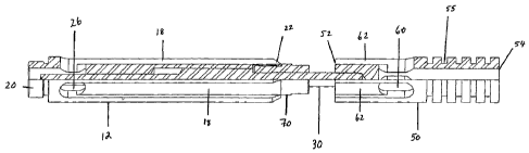
apparatus (10) comprises a substantially hollow cylindrical housing (12)
having a first end (20)
13
WO 2011/147031 PCT/CA2011/000626
and a second end (22). The cylindrical housing (12) has an outer surface (16),
an inner surface
(24), defines a central passageway (14). The central passageway (14) extends
from the first end
(20) to the second end (22). The first end (20) of the cylindrical housing
(12) is adapted to be
attached directly to a traveling valve assembly and as shown in Figures 3 and
6, in one
embodiment the first end (20) of the cylindrical housing (12) has a male
thread configuration that
mates with a complementary female thread on the valve cage of the traveling
valve assembly.
As shown in Figure 2, in one embodiment the apparatus (10) of the present
invention is
mounted on the plunger (88) in a position immediately below the traveling
valve assembly (94).
The cylindrical housing (12) has at least one fluid port (26) proximate to the
first end (20)
extending out from the inner surface (24) of the passageway (14) to the outer
surface (16) for
fluid communication between the passageway (14) and the outer surface (16).
The outer surface
(16) of the cylindrical housing (12) defines a fluid passage (18) that extends
along the outer
surface (16) from the fluid port (26) to the second end (22). Having reference
to the figures, it
can be understood that there can be multiple ports and corresponding fluid
passages configured
in a similar manner, the fluid ports each entering the central passageway (14)
at a common point.
As shown in Figures 3, 4 and 5, in a one embodiment there are three ports (26)
and three fluid
passages (18) on the cylindrical housing (12).
As shown in Figure 3, in one embodiment, the central passageway (14) of the
cylindrical
housing (12) has varying diameters along the length of the cylindrical housing
(12). Proximate
to the first end (20) the passageway (14) is bored such that the diameter is
greater than the
adjacent valve opening, or the internal diameter of the ball if a ball and
seat valve is being
14
WO 2011/147031 PCT/CA2011/000626
employed. This widened section of the passageway (14) receives fluid from the
fluid
ports (26) holding it prior to entry into the adjacent valve (93).
As shown in Figure 3, in one embodiment the central passageway (14) is
narrowed in the
middle to form a guide for the piston (30). Moving towards the second end of
the cylindrical
housing (12) the diameter of the central passage (14) flares forming a
shoulder (29). As will be
described in more detail later, this shoulder (29) engages the piston (30) on
the down stroke of
the plunger (88) restricting the amount of the protrusion of the first end
(32) of the piston (30)
out of the first end (20) of the cylindrical housing (12) and also confining
the piston (30) within
the cylindrical housing (12).
In one embodiment, the second end (22) of the cylindrical housing (12) is
adapted to
receive a bushing ring (70) that when installed acts to retain the piston (30)
in the cylindrical
housing (12) during the upstroke of the plunger (88) by means of engaging a
lower shoulder (42)
on the piston (30). The bushing ring (30) may have a threaded into the second
end (22) of the
cylindrical housing (12). As shown in Figure 11, the bushing ring may also
have wrench flats
(74) defined on its outer surface to aid with installation and removal.
Although the Figures
depict a bushing ring (70) it may be understood that any other suitable means
of retaining the
piston (30) within the cylindrical housing (12) may be employed at the second
end (22) of the
cylindrical housing (12).
The elongate piston (30) is shown in Figures 7 and 8 and it has a first end
(32) and a
second end (34). The first end (32) is adapted to engage the valve (93) of the
valve assembly
(94) on the down stroke of the plunger (88). If a ball and seat valve is being
employed, then the
first end (32) of the piston (30) may have concave configuration (not shown in
the figures) to
WO 2011/147031 PCT/CA2011/000626
facilitate enhanced contact with the ball. The elongate piston (30) has a
widened portion in
its central portion forming an upper shoulder (40) and a lower shoulder (42)
that engage a
shoulder (29) in the central passageway (14) of the cylindrical housing and
the bushing ring (70)
respectively as previously described.
The second end (34) of the piston (30) is releasably attached to a cylindrical
plunger
element (50) having a first end (52) and a second end (54) and an outer
surface (56). Any
suitable attachment means may be used however, as shown in the Figures, in one
embodiment
the second end (34) of the piston (30) threads into (36, 53) the first end
(52) of the plunger
element (50). As shown in Figures 12, 13 and 14, the plunger element (50) has
a central bore
(58) extending from its second end (54) to position proximate to its first end
(52). As also shown
in Figures 12, 13 and 14, the plunger element (50) has at least one fluid port
(60) extending from
the central bore (58) to its outer surface (56) for fluid communication
between the central bore
(58) and the outer surface (56). The outer surface (56) of the plunger element
(50) defines a
fluid passage (62) that extends from the fluid port (60) to the first end (52)
of the plunger
element (50). The plunger element (50) may have a plurality of ports and fluid
passages and as
shown in Figures 13 and 14, and in a preferred embodiment, three ports (60)
and three fluid
passages (62) are utilized.
The plunger element (50) also has means to resist the reciprocating movement
of the
plunger (88) which provides a forceful drive for the piston (30). Any suitable
resistive means
may be employed but as shown in the Figures, in one embodiment a plurality of
sealing rings
(51) are used that are seated in grooves (55) around the circumference of the
plunger element
(50). The sealing rings (51) engage the walls of the barrel cylinder (92)
providing frictional
16
WO 2011/147031 PCT/CA2011/000626
resistive force and also exert a hydrostatic force on the surrounding fluid as
they are moved
through the fluid. This promotes rapid and forceful movement of the piston
(30) as the plunger
(88) reciprocates on its up and down strokes within the cylindrical barrel
(92). The sealing rings
(51) also act to wipe the sides of the barrel cylinder (92) which aids in the
lifting of fluid and in
i minimizing the build of debris such as sand in the barrel cylinder (92). The
sealing rings (51)
may be manufactured from any suitable material, such as an elastomer or a
rubber, and can be
easily interchanged in the event of wear or incompatibility with the fluid
being produced in the
well.
Figure 17 depicts the assembled apparatus and shows the relationship of the
cylindrical
housing (12), the ring bushing (70), the piston (30) and the plunger element
(50).
Having regard to the Figures 15 and 16, and the foregoing description, the
operation of
the apparatus will now be described. A shown in Figure 15, on the down stroke
of the plunger
(88), the traveling valve (94) descends into the cylindrical barrel (92)
towards the standing valve
(96). The standing valve (96) closes. The resistive force exerted by the
plunger element (50)
i drives the piston (30) upwards to move into a first position whereby the
upper shoulder (40) of
the piston (30) engages the shoulder (29) in the central passageway (14) of
the cylindrical
housing (12). In this position, the first end (52) of the plunger element (50)
and the second end
(22) of the cylindrical housing (12) abut. The fluid passages (18, 62) align
forming continuous
fluid passages between the fluid ports (26) in the cylindrical housing (12)
and the fluid ports (60)
in the plunger element (50). Fluid and gas in the cylinder barrel (92) between
the standing valve
(96) and the traveling valve assembly (94) move into the central bore (58) of
the plunger element
(50) and then flow into the fluid ports (60) in the plunger element (50). The
fluid and gas moves
17
WO 2011/147031 PCT/CA2011/000626
from the fluid ports (60) in the plunger element (50) up the fluid passage
(62, 18) defined by
the outer surfaces of the plunger element (50) and the cylindrical housing
(12), and into the fluid
ports (26) in the cylindrical housing (12). The fluid and gas enters the
central passage way (14)
adjacent to the first end (20) of the cylindrical housing (12) and then flows
to the valve above
(93). The first end (32) of the piston (30) protrudes through the first end
(20) of the cylindrical
housing (12) and into the adjacent valve assembly (94). In the case of a ball
and seat valve, the
first end of the piston (32) engages the ball (93) and lifts it from its seat
(95), opening the valve
(90). In the case of a flapper valve (not shown), the first end (32) of the
piston (30) engages and
lifts the flapper.
The gas and fluid can flow through the open valve into the space above the
valve
assembly (94). Thus, with each down stroke of the plunger (88), the valve (90)
is mechanically
opened to ensure the constant flow of fluid and gas through the traveling
valve assembly (94). It
can be understood that in this manner, fluid flows from the bottom of the gas
release apparatus
(10) to the valve (90) not through a central passage, but rather around the
outside of the
apparatus by means of the ports and defined fluid passageways. The fluid
effectively bypasses
the piston (30) housed in the cylindrical housing (12). Furthermore, in one
embodiment, the
depth, width and number of the fluid passageways are configured such that the
combined cross-
sectional flow area of fluid around the outside of the apparatus (10) is less
restricted than the
valve opening itself. This flow design has reduced flow restrictions in
comparison to a central
passageway and mitigates the problem of pressure drop in the produced fluid.
On the upstroke of the plunger (88), the resistive force of the plunger
element (50) acts to
pull the piston (3) down into its second position whereby the lower shoulder
(42) of the piston
18
WO 2011/147031 PCT/CA2011/000626
(30) engages the bushing ring (70). The first end (32) of the piston (30)
disengages from the
valve (90) and retracts into the central passageway (14) of the cylindrical
housing (12). In the
case of a ball and seat valve, the ball is forced back onto the seat and in
the case of a flapper
valve, the flapper is shut closing the valve in both instances. The plunger
(88) is then able to lift
the body of fluid immediately above the valve assembly (94). The standing
valve (96) opens and
fluid and gas is drawn into the barrel cylinder (92) ready for the next down
stroke of the plunger
(88). This process is repeated such that fluid is continually lifted to the
surface.
In one embodiment, the apparatus is manufactured from stainless steel to
minimize
corrosion and wear. However, it can be understood that any suitable materials
as would be
utilized by one skilled in the art may be used to construct the apparatus.
The present apparatus may be constructed in varying sizes for use with
differing
downhole environments, casing sizes and types of traveling valve assemblies.
Typical sizes
include without limit, two inch diameter and one and a half inch diameter. It
can be understood
that the apparatus can be constructed to meet the size requirements of any
particular end user.
i In addition to improved fluid flow, other advantages of the present
invention include the
relative ease with which it can be assembled and disassembled because of the
threaded
connections. The present invention also has relatively few parts compared to
prior art solutions
making it more efficient and simpler to use. Worn parts, such as the sealing
rings can be quickly
isolated and easily interchanged with replacement parts. When used with a ball
and seat valve,
the present invention also allows free movement of the ball within the valve
cage. As a result,
the first end (32) of the piston (30) will not be restricted to contacting the
ball (93) at the same
point each time thereby reducing wear.
19
WO 2011/147031 PCT/CA2011/000626
As will be apparent to those skilled in the art, various modifications,
adaptations and
variations of the foregoing specific disclosure can be made without departing
from the scope of
the invention claimed herein.