Note: Descriptions are shown in the official language in which they were submitted.
CA 02792746 2012-09-10
1
DESCRIPTION
MACHINE AND METHOD OF MANUFACTURING A LOW FIRE-SPREADING
WEB AND A METHOD OF MANUFACTURING A LOW FIRE-SPREADING
WRAPPING PAPER USED FOR CIGARETTES
Technical Field
The present invention relates to a machine and method
of manufacturing a low fire-spreading web that provides a
low fire-spreading property to cigarettes, and a method of
lo manufacturing a low fire-spreading wrapping paper used for
cigarettes.
Background Art
A low fire-spreading wrapping paper used for
cigarettes has lately grown popular. This low fire-
spreading wrapping paper prevents fire from spreading to a
combustible material in the event that a lighted cigarette
using the wrapping paper is dropped on the combustible
material. The cigarette includes smoking material such as
shred tobacco, and paper wrapping the smoking material.
This paper is the low fire-spreading wrapping paper (for
example, see FIG. 2 of Patent Document 1).
More specifically, the low fire-spreading wrapping
paper disclosed in Patent Document 1 includes a paper web
and bands that are longitudinally arranged in the web at
predetermined intervals. These bands are formed by
applying a combustion inhibitor onto the web. The
combustion inhibitor is generally applied as an aqueous
solution. The web applied with the combustion inhibitor
is dried by a dryer to be formed into a low fire-spreading
wrapping paper.
After being dried, the wrapping paper is reduced in
width as a result of drying shrinkage by about 3 percent
to about 7 percent. For example, if the original width of
CA 02792746 2012-09-10
2
the wrapping paper is 1040 mm, the paper width will become
1010 mm at a shrinkage rate of 3 percent, and 970 mm at a
shrinkage rate of 7 percent. The dried web is provided
with slits of 27 mm wide, and is wound into rolls as
wrapping papers each having a width of 27 mm. While the
wrapping paper dried at a 3 percent shrinkage rate can
make 37 rolls of 27 mm slits, the one dried at a 7 percent
shrinkage rate makes 35 rolls. In this way, the different
shrinkage rates produce different numbers of wrapping
lo paper rolls, which destabilizes the manufacture.
Moreover, because the combustion inhibitor applied onto
the web are fixed in amount and application intervals, if
the number of the produced rolls is different from
wrapping paper to wrapping paper, the application amount
of the combustion inhibitor is also unequal from roll to
roll. This results in a failure of producing wrapping
papers of the stable quality.
In order to maintain a constant shrinkage rate,
drying temperature and web tension are controlled.
However, it is necessary to change the temperature setting
with the seasons, and also from morning to afternoon. It
is thus troublesome to maintain the constant shrinkage
rate.
Prior Art Document
Patent Document
Patent Document 1
Japanese Patent Publication (Kohyo) No. 2004-512849
Summary of the Invention
Problem to be Solved by the Invention
The invention has been made in light of the above-
mentioned conventional art. It is an object of the
invention to provide a machine and method of manufacturing
a low fire-spreading web that is capable of maintaining a
CA 02792746 2014-05-20
3
constant shrinkage rate after being dried, regardless of
surrounding environments, and a method of manufacturing a
low fire-spreading wrapping paper used for cigarettes.
Means for Solving the Problem
In order to accomplish the above object, the invention
provides a machine of manufacturing a low fire-spreading
web, comprising:
a travel path through which a paper web travels, the
travel path extending from a feed reel to a take-up reel;
an applicator that is interposed in the travel path
and used to apply a combustion inhibitor onto the web; and
a dryer that dries the web applied with the combustion
inhibitor, further comprising:
a detector that measures a parameter indicative of
width of the web that has passed through the dryer, the
detector being a sensor that directly measures the width of
the web; and
a controller that controls a drying condition of the
dryer, the controller obtaining, from a measurement result
provided by the sensor, a shrinkage rate of the width of
the web, the controller changing the drying condition of
the dryer on the basis of the shrinkage rate for keeping
the shrinkage rate within a preset range.
According to a preferred aspect, the detector is a
sensor that directly measures the width of the web.
According to a preferred aspect, the controller has a
calculating section that receives a measurement result from
the sensor and finds a shrinkage rate in a width direction
of the web, a determining section that makes a
determination as to whether the shrinkage rate is within a
preset range, and a controlling section that changes the
CA 02792746 2014-05-20
4
drying condition of the dryer when the shrinkage rate is
outside the preset range.
According to a preferred aspect, the sensor is a CCD
laser transmission sensor.
According to a preferred aspect, the drying condition
is drying temperature.
According to a preferred aspect, the drying
temperature is an in-furnace temperature in the dryer or
hot-air temperature of hot air supplied into the drying
furnaces.
According to a preferred aspect, the applicator
includes first and second tanks that communicate with each
other and contain the combustion inhibitor; a supply path
for supplying the combustion inhibitor from the first tank;
an application unit for directly applying onto the web the
combustion inhibitor supplied through the supply path; a
capacity measurer for measuring a capacity of the
combustion inhibitor in the first tank while the combustion
inhibitor is being applied onto the web; and an adjusting
unit that adjusts the capacity of the combustion inhibitor
supplied from the second tank to the first tank so that the
capacity of the combustion inhibitor in the first tank,
which is obtained by the capacity measurer, is constant.
According to a preferred aspect, the machine further
includes, as the detector, a moisture meter that measures a
moisture content of the web.
The invention further provides a method of
manufacturing a low fire-spreading web, comprising:
an applying step that makes a paper web travel along a
travel path and applies a combustion inhibitor onto the
web, the travel path extending from a feed reel to a take-
CA 02792746 2014-05-20
, .
4a
up reel; and
a drying step that dries the web applied with the
combustion inhibitor, further comprising:
a controlling step that, after the drying step,
measures the width of the web using a detector, the
detector being a sensor that directly measures the width of
the web, and controls a drying condition in the drying step
on the basis of a measurement result provided by the
sensor, wherein the measurement result is a shrinkage rate
of the width of the web, by adjusting the drying condition
of the dryer on the basis of the shrinkage rate for keeping
the shrinkage rate within a preset range.
According to a preferred aspect, the web is applied
with the combustion inhibitor having constant viscosity in
the applying step.
The invention further provides a method of
manufacturing a low fire-spreading wrapping paper used for
CA 02792746 2012-09-10
cigarettes, in which the low fire-spreading web undergoes
an unwrinkling step that takes wrinkles and a slit-forming
step that forms slits in the web that has been unwrinkled
and cuts the web into predetermined width, and is formed
5 into wrapping paper for cigarettes.
Technical Advantage of the Invention
The manufacturing machine of the low fire-spreading
web according to the invention has the detector that
measures the parameter indicative of the width of the web
lo that has passed through the dryer, and the controller that
controls the drying condition of the dryer on the basis of
the measurement result obtained by the detector so that
the web width falls within the allowable range. The
drying condition can therefore be properly controlled to
achieve a predetermined shrinkage rate, reflecting the
width of the dried web (shrinkage rate).This makes it
possible to manufacture the wrapping paper of the stable
quality in the future.
As the detector, in particular, a sensor that
actually measures the web width is utilized.
Having the calculating, determining, and controlling
sections, the controller is capable of accurately
recognizing the state of the web by finding the shrinkage
rate of the dried web, and based upon this, changing the
drying condition. Consequently, the wrapping paper of the
more stable quality can be manufactured.
Using the CCD laser transmission sensor as the sensor
enables the web width to be measured with accuracy.
Moreover, since the specific parameter controlled by
the controller is the drying temperature, the web with a
desired shrinkage rate can be produced by a simple method.
The drying temperature to be controlled is the in-
furnace or hot-air temperature, so that the web with the
CA 02792746 2012-09-10
6
desired shrinkage rate can be properly produced by a
simple method.
Because of the constant capacity of the combustion
inhibitor in the first tank installed in the applicator,
the combustion inhibitor applied onto the web has constant
viscosity. The web passing through the dryer is
accordingly constant in quality, leading to the constant
quality of the dried web. A change in the shrinkage rate
is therefore caused only by the dryer. This means that
io the shrinkage rate of the web can be precisely maintained
constant simply by controlling the drying condition.
Since the moisture meter is provided as the detector,
the moisture content of the dried web can be measured with
the moisture meter, and the controller controls the drying
condition, reflecting the moisture content. The drying
condition is thus properly controlled so that the dried
web has the predetermined shrinkage rate. This makes it
possible to manufacture the wrapping paper of the stable
quality in the future.
With the method of manufacturing the low fire-
spreading web according to the invention, the drying
condition can be properly controlled to achieve the
predetermined shrinkage rate, reflecting the width of the
dried web (shrinkage rate). This makes it possible to
manufacture the wrapping paper of the stable quality in
the future.
Moreover, the dried web has constant quality since
the viscosity of the combustion inhibitor applied onto the
web is maintained constant. As a change in the shrinkage
rate of the web is caused only by an influence of the
drying step, the shrinkage rate can be accurately
maintained constant simply by the control of the drying
condition.
CA 02792746 2012-09-10
7
With the method of manufacturing the low fire-
spreading wrapping paper according to the invention, the
wrapping paper for cigarettes is manufactured with the web
that is produced to have a stable shrinkage rate, through
the unwrinkling step that takes wrinkles and the slit-
forming step that forms the slits in the unwrinkled web
and cuts the web into the predetermined width.
Consequently, the low fire-spreading wrapping paper of the
stable quality can be manufactured.
lo Brief Description of the Drawings
FIG. 1 is a schematic view of a machine of
manufacturing a low fire-spreading wrapping paper
according to the invention;
FIG. 2 is a schematic view of an applicator; and
FIG. 3 is a flowchart showing the process of
manufacturing wrapping paper by using the machine of
manufacturing a low fire-spreading wrapping paper
according to the invention.
Best Mode for Carrying out the Invention
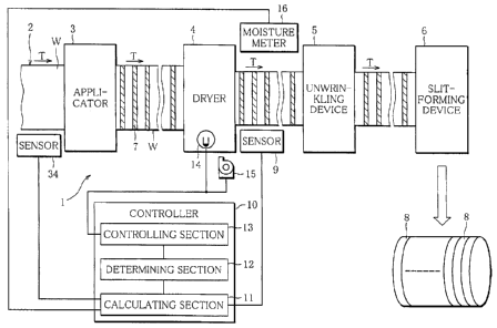
FIG. 1 is a schematic plan view. A machine of
manufacturing a low fire-spreading web according to the
invention is a part of a manufacturing machine 1 of a low
fire-spreading wrapping paper. The manufacturing machine
1 includes a travel path 2, an applicator 3, a dryer 4, an
unwrinkling device 5, and a slit-forming device 6. The
machine of manufacturing a low fire-spreading web is
formed of the applicator 3, the dryer 4, and a controller
10 mentioned later. The applicator 3, the dryer 4, the
unwrinkling device 5, and the slit-forming device 6 are
all situated on the travel path 2. Web W made of paper is
reeled out from an original roll (not shown) that is a
winding of the web W so as to travel through the travel
path 2 in a direction of arrow T. The paper width of the
CA 02792746 2012-09-10
8
web W is first measured by a sensor 34. The web W then
passes through the applicator 3. The applicator 3
partially applies a combustion inhibitor 7 onto the web W.
The combustion inhibitor 7 is applied onto a plurality of
places of the web W at longitudinally spaced intervals to
extend across the web W in the width direction. The web W
applied with the combustion inhibitor passes through the
dryer 4. The dryer 4 is equipped with a plurality of
drying furnaces (not shown). The web W passes through
lo these drying furnaces to be dried. After being dried, the
web W is unwrinkled by the unwrinkling device 5. The web
W is then provided with slits by the slit-forming device
6, and is formed into rolls of wrapping paper 8.
A sensor 9 serving as a detector is placed near the
outlet of the dryer 4. The sensor 9 measures the width of
the web W that has passed through the dryer 4. The sensor
9 is connected to the controller 10. The controller 10
controls a drying condition, and is connected to the dryer
4. In short, the controller 10 controls the drying
condition of the dryer 4 so that the width of the web W
falls within an allowable range on the basis of the
measurement result of the sensor 9. The wrapping paper 8
of the stable quality can be manufactured by performing
the drying on the proper drying condition, reflecting the
width of the dried web W.
To be specific, the controller 10 includes a
calculating section 11, a determining section 12, and a
controlling section 13. The calculating section 11
receives the measurement results of parameters indicative
of the widths (actual widths of the web W) from the
sensors 34 and 9, and finds a width shrinkage rate of the
dried web W. To that end, the sensors 34 and 9 are
directly connected to the calculating section 11. The
CA 02792746 2012-09-10
9
determining section 12 makes a determination as to whether
the shrinkage rate of the dried web W is within a preset
range. The preset range of the shrinkage rate is properly
changed depending upon the wrapping paper to be
manufactured or various other conditions. The controlling
section 13 changes the drying condition of the dryer 4
when the shrinkage rate of the web W is outside the preset
range. The shrinkage rate of the dried web W is reflected
to the drying condition, so that the web W with a constant
lo shrinkage rate can be produced. As described above, the
state of the web W is accurately recognized by finding the
shrinkage rate of the dried web W, and based upon this,
the drying condition is changed. Consequently, the
wrapping paper 8 of a more stable quality can be
manufactured. Because of the constant shrinkage rate, the
same number of rolls of wrapping paper can be obtained
from each original roll. In addition, if a function is
preliminarily fixed, the application amount of the
combustion inhibitor 7 accordingly becomes uniform with
respect of each roll, producing the wrapping paper 8 of
the stable quality.
In this specification, the drying condition
controlled by the controller 10 is drying temperature.
The drying temperature is the temperature to be applied to
the web W. The web W with a desired shrinkage rate can be
easily obtained simply by changing the temperature
condition. More specifically, the drying temperature is
an in-furnace temperature in the dryer 4 through which the
web W passes or a hot-air temperature of the hot air
supplied into the drying furnaces. The in-furnace
temperature is changed by various methods, including
sending air into the furnaces and heating the furnaces
with a heater or the like. The hot-air temperature is
CA 02792746 2012-09-10
changed by changing the temperature of the hot air
supplied into the drying furnaces. The controlling
section 13 is connected to temperature indicators 14
located in the drying furnaces. The in-furnace
5 temperature is adjusted according to the temperature of
the temperature indicators 14. To adjust the hot-air
temperature, the controlling section 13 is connected to a
hot-air supplier 15 installed in the dryer 4, thereby
adjusting a supply temperature. As mentioned above, since
lo the drying temperature to be controlled is the in-furnace
or hot-air temperature, the web W with the desired
shrinkage rate can be surely produced by a simple method.
Preferably, the temperature of the drying furnaces located
downstream is set lower than that of the furnaces located
upstream, and the downstream drying temperature that
influences drying shrinkage is controlled. For example,
the upstream drying temperature is set at 130, and the
downstream drying temperature 80. A quick response can be
made when the controlling section 13 requires a change in
the drying condition since the downstream drying
temperature is equal to or lower than 100. Consequently,
the temperature can be promptly set at a predetermined
temperature.
The sensor 9 is a CCD laser transmission sensor. In
this case, the sensor 9 is disposed on each of the width-
directional sides of the web W that travels through the
travel path 2. This CCD laser transmission sensor is a
laser displacement sensor. A charge-transfer device
called CCD (charge coupled device) is used as a light
receiving element. The CCD method detects a light
quantity of each pixel of the CCD, and is then capable of
accurately detecting a peak position of the light
quantity. The width of the web W can be thus measured
CA 02792746 2012-09-10
11
with accuracy.
A moisture meter 16 serving as a detector is also
provided near the outlet of the dryer 4. The moisture
meter 16 measures a moisture content of the web W that has
passed through the dryer 4. The moisture meter 16 is
connected to the calculating section 11 of the controller
10. The calculating section 11 is further capable of
finding a moisture content percentage of the web W. The
determining section 12 is capable of determining whether
the moisture content percentage is within a preset range.
When the moisture content percentage is outside the preset
range, the controlling section 13 changes the drying
condition of the dryer 4 so that the moisture content of
the web W falls within the allowable range. In this
manner, the moisture content of the dried web W is
measured by the moisture meter 16, and the drying
condition is controlled by the controller 10 reflecting
the moisture content. The drying condition is thus
properly controlled so that the dried web W has the
predetermined shrinkage rate. In result, the wrapping
paper 8 of the stable quality can be manufactured. The
control based on the sensor 9 and that based on the
moisture meter 16 may be carried out either simultaneously
or alternatively.
As is apparent from FIG. 2, the applicator 3 has a
first tank 18, a second tank 19, a supply path 20, an
application unit 21, a capacity measurer 22, and an
adjusting unit 23. The first and second tanks communicate
with each other, and contain the combustion inhibitor 7.
The supply path 20 is for supplying the combustion
inhibitor 7 from the first tank 18 to the application unit
21. For that reason, a starting end of the supply path 20
is located inside the first tank 18, and the combustion
CA 02792746 2012-09-10
12
inhibitor 7 in the first tank 18 is sent by a pump 24 to a
finishing end in the direction of arrow P. The
application unit 21 directly applies onto the web W the
combustion inhibitor 7 supplied from the supply path 20.
An application method using the application unit 21
will be described below in detail.
The web W travels through the travel path 2 (FIG. 1).
At this time, the web W is reeled out from a feed reel,
and is stretched to be taken up by a take-up reel. The
lo application unit 21 includes a platen 25 and a gravure
roller 26. The platen 25 and the gravure roller 26 are
situated across the travel path 2, or across the web W.
They are rotatable in opposite directions to each other.
The gravure roller 26 has a flute pattern (not shown) on
its outer circumferential surface. The flutes are
arranged at regular intervals in a circumferential
direction of the gravure roller 26 so that the combustion
inhibitor 7 is applied onto a plurality of places at
longitudinally spaced intervals to extend across the web W
in the width direction.
A furnisher roller 27 is in rotating contact with the
outer circumferential surface of the gravure roller 26. A
nozzle 28 is located above the furnisher roller 27. The
nozzle 28 is connected to the first tank 18 through the
supply path 20. While in operation, the pump 24 of the
supply path 20 sends the combustion inhibitor in the first
tank 18 through the supply path 20 to the nozzle 28. The
nozzle 28 supplies the combustion supplier to between the
gravure roller 26 and the furnisher roller 27.
A doctor blade 29 is situated near the gravure roller
26. The doctor blade 29 has a tip end in sliding contact
with the outer circumferential surface of the gravure
roller 26. A recovery chute 30 is disposed under the
CA 02792746 2012-09-10
13
gravure roller 26 and the doctor blade 29. The recovery
chute 30 extends to the first tank 18. The combustion
inhibitor 7 that is not applied onto the web W returns to
the first tank 18 and is sent again by the pump 24 to the
supply path 20.
The doctor blade 29 scrapes extra combustion
inhibitor off the outer circumstantial surface of the
gravure roller 26. The combustion inhibitor scraped off
is returned to the first tank 18 via the recovery chute 30
io (in the direction of arrow Q in FIG. 2). While the
manufacturing machine 1 is working, the combustion
inhibitor in the first tank 18 is in a constant flowing
state, circulating between a position at which the
combustion inhibitor is applied onto the web W (gravure
roller 26) and the first tank 18.
The fist tank 18 is placed on a weight scale 31. The
weight of the first tank 18, or the capacity of the
combustion inhibitor 7, is measured by the capacity
measurer 22. The capacity measurer 22 is equipped, for
example, with a display. Based upon a measurement result,
the display shows a remaining amount, or consumed amount,
of the combustion inhibitor in the first tank 18. The
measurement result is transmitted to the adjusting unit
23. The adjusting unit 23 adjusts a flow rate of the
combustion inhibitor 7 by opening/closing a valve 33 of a
communication pipe 32 connecting the first and second
tanks 18 and 19 to each other so that the combustion
inhibitor 7 in the first tank 18 has constant capacity.
The pipe between the first and second tanks 18 and 19 is
kept warm at constant temperature.
The combustion inhibitor 7 has constant temperature,
and the capacity of the combustion inhibitor 7 in the
first tank 18 is maintained constant, so that the
CA 02792746 2012-09-10
14
combustion inhibitor 7 applied onto the web W has constant
viscosity. The quality of the web W passing through the
dryer 4 can be then maintained constant, which makes
constant the quality of the dried web W. A change in the
shrinkage rate is therefore caused only by the influence
of the dryer 4, meaning that the shrinkage rate of the web
W can be accurately maintained constant simply by the
control of the drying condition. The remaining amount of
the combustion inhibitor 7 in the first tank 18 may be
lo measured by measuring a liquid level in the tank or by any
other method as long as the viscosity of the combustion
inhibitor 7 is maintained constant.
A method of manufacturing a low fire-spreading
wrapping paper using the manufacture machine 1 according
to the invention will be described below with reference to
FIG. 3. Reference marks in the following description are
identical to those used in FIGS. 1 and 2.
Upon activation of the manufacturing machine 1, the
web W is reeled out from the original roll and travels
through the travel path 2, and the paper width of the web
W is measured before the combustion inhibitor 7 is applied
onto the web W (Step S1). After the web W enters the
applier 3, the capacity measurer 22 carries out
measurement to determine whether the capacity of the
combustion inhibitor 7 in the first tank 18 is
predetermined capacity (Step S2). If the capacity is the
predetermined capacity, the combustion inhibitor 7 is
directly applied onto the web W (Step S3). The web W is
continuously applied with the combustion inhibitor 7, and
travels through the travel path 2. To apply the
combustion inhibitor 7 onto the web W reduces the capacity
of the combustion inhibitor 7 in the first tank 18. The
capacity of the combustion inhibitor 7 in the first tank
CA 02792746 2012-09-10
18 accordingly becomes equal to or less than the
predetermined capacity. In order to maintain the constant
capacity, the combustion inhibitor 7 is supplied from the
second tank 19 to the first tank 18 (Step S4). The step
5 of applying the combustion inhibitor 7 onto the web W is
carried out while monitoring the capacity of the
combustion inhibitor 7 in the first tank 18. To put it
differently, while the web W is being applied with the
combustion inhibitor 7 in the applier 3, Steps S2 to S4
lo are repeatedly performed.
The web W is directly subjected to the drying step in
the dryer 4 (Step S5). Following the drying step, the
width of the web W that is reeled out from the dryer 4,
namely, the width of the dried web W, is measured (Step
15 S6). On the basis of the width that has been measured,
the shrinkage rate resulting from the drying of the web W
is found by the calculation of the calculating section 11
(Step S7). Thereafter, the determining section 12 makes a
determination as to whether the shrinkage rate is within
the preset range (Step S8). If the shrinkage rate is
within the preset range, the drying step is continued. If
the shrinkage rate is outside the preset range, the drying
condition is changed so that the shrinkage rate falls
within the preset range (Step S9), and then, the drying
step is continued. The controlling step including Steps
S6 to S9 is repeated during the drying step, that is,
until there is no undried web W left.
If there is no undried web W, the drying step in the
dryer 4 is finished. To smooth the wrinkles of the shrunk
web W, an unwrinkling step is carried out by the
unwrinkling device 5 (Step S10). A slit-forming device 6
performs a slit-forming step, thereby forming slits with
CA 02792746 2012-09-10
16
predetermined width in the web W and manufacturing rolls
of wrapping paper 8 (Step S11).
Reference marks
1 machine of manufacturing a low fire-spreading
wrapping paper
2 travel path
3 applier
4 dryer
5 unwrinkling device
6 slit-forming device
7 combustion inhibitor
8 wrapping paper
9 sensor
10 controller
11 calculating section
12 determining section
13 controlling section
14 temperature indicator
15 hot-air supplier
16 moisture meter
18 first tank
19 second tank
20 supply path
21 application unit
22 capacity measurer
23 adjusting unit
24 pump
25 platen
26 gravure roller
27 furnisher roller
28 nozzle
29 doctor blade
30 recovery chute
CA 02792746 2012-09-10
17
31 weight scale
32 communication pipe
33 valve
34 sensor