Note: Descriptions are shown in the official language in which they were submitted.
CA 02792791 2012-09-11
1
DESCRIPTION
Title of the Invention: ELECTRICITY GENERATION DEVICE
Technical Field
[0001] The present invention relates to an electricity
generation device for generating electricity by supplying a
fuel gas to a fuel electrode of a fuel cell thereof.
Background Art
[0002] A fuel cell comprises a fuel electrode and an air
electrode sandwiching an electrolyte. A fuel gas or the
like is supplied to the electrodes to generate electricity.
In a solid oxide fuel cell (SOFC), in particular, a fuel
electrode (hydrogen electrode) and an air electrode (oxygen
electrode) are joined to an electrolyte made of a solid
oxide. The fuel electrode is supplied with a fuel gas and
the air electrode is supplied with air or the like, whereby
high-output electric power can be generated. The solid
oxide fuel cell can use, as the fuel gas, not only hydrogen
gas but a gas containing a large amount of carbon monoxide
(e.g., exhaust gas of a motor vehicle driven by an internal
combustion engine).
[00031 Such a solid oxide fuel cell is disclosed in
Patent Document 1. In the disclosed fuel cell, the fuel
and air electrodes are exposed to the internal spaces of
respective different chambers to be supplied with hydrogen
and oxygen, respectively. The solid oxide fuel cell with
such a configuration is referred to as a dual-chamber type.
In the case of arranging the dual-chamber SOFC in an
exhaust pipe through which exhaust gas flows, hydrogen is
let into the fuel electrode-side chamber by utilizing the
flow of the exhaust gas, and oxygen is fed into the air
electrode-side chamber by using a pump or the like.
[0004] It is not desirable, however, to use a pump or
CA 02792791 2012-09-11
2
the like to supply the air electrode with oxygen contained
in air, because the device as a whole is increased in size.
The air electrode may be exposed to the atmosphere in order
to dispense with the pump or the like, but from the
standpoint of protection of the air electrode, the air
electrode should preferably be arranged in a chamber.
Accordingly, there has been a demand for methods whereby an
air electrode arranged in a chamber can be efficiently
supplied with oxygen contained in air without the need to
use a separate air supply device.
Prior Art Document
Patent Document
[0005] Patent Document 1: Japanese Laid-open Patent
Publication No. 2000-156239
Summary of the Invention
Problems to be Solved by the Invention
[0006] The present invention provides an electricity
generation device whereby an air electrode arranged in a
chamber can be efficiently supplied with oxygen contained
in air without the need to use a separate air supply
device.
Means for Solving the Problems
[0007] To achieve the object, the present invention
provides an electricity generation device using a fuel cell
having a fuel electrode and an air electrode to which a
fuel gas and air are supplied, respectively, the
electricity generation device comprising: a fuel gas
conduit through which the fuel gas flows; a cover
configured to cover an outside of the fuel gas conduit and
cooperating with a peripheral wall of the fuel gas conduit
to form an air passage therebetween, the air passage
extending along the fuel gas conduit; an air inlet hole
formed through the cover to allow air to flow into the air
CA 2792791 2017-04-03
3
passage; and an air outlet hole provided downstream of the
air electrode exposed to the air passage, to cause the fuel
gas conduit and the air passage to communicate with each
other.
More particularly, there is provided an electricity
generation device comprising a fuel cell having a fuel
electrode and an air electrode to which a fuel gas and air
are supplied, respectively, comprising:
a fuel gas conduit through which the fuel gas flows;
a cover configured to cover an outside of the fuel gas
conduit and cooperating with a peripheral wall of the fuel
gas conduit to form an air passage therebetween, the air
passage extending along the fuel gas conduit;
an air inlet hole formed through the cover to allow
air to flow into the air passage; and
an air outlet hole provided downstream of the air
electrode exposed to the air passage, to cause the fuel gas
conduit and the air passage to communicate with each other,
wherein the air outlet hole is configured to create a flow
of air in the air passage from a flow of the fuel gas
through the fuel gas conduit.
[0008] Preferably, the fuel electrode forms an inner
pipe, the cover forms an outer pipe cooperating with the
inner pipe to constitute a double pipe structure, and the
outer pipe is fixed to a fuel gas pipe continuous with the
inner pipe and passing the fuel gas therethrough.
[0009] The air inlet hole preferably includes a
plurality of air inlet holes.
Also, preferably, the fuel gas is exhaust gas of a
motor vehicle.
Advantageous Effects of the Invention
[0010] According to the present invention, the air
CA 2792791 2017-04-03
4
outlet hole communicating with the fuel gas conduit is
provided at the downstream side of the air passage. Thus,
when the fuel gas is flowing at high speed through the fuel
gas conduit, negative pressure is generated via the air
outlet hole, so that the air in the air passage flows out
into the fuel gas conduit. As a result, a unidirectional
flow of air is created in the air passage, and since air
can be efficiently supplied to the air electrode,
electricity generation efficiency can be improved. The
flow of air created by making use of the negative pressure
is gentle, and therefore, the fuel gas is not cooled by the
air, enabling electricity generation at high temperatures.
Consequently, the electricity generation efficiency can be
further improved.
[0011] Also, according to the present invention, the
double pipe structure is employed which is constituted by
the inner pipe for passing the fuel gas and the outer pipe
for passing air, and therefore, the electricity generation
device as a whole can be made compact in size. Since the
outer pipe is fixed to the fuel gas pipes located upstream
and downstream thereof as viewed in the flowing direction
of the fuel gas, the material of the outer pipe may be
selected taking account only of strength. A suitable
material can therefore be selected for the outer pipe so as
to prevent deterioration with use.
[0012] Further, according to the present invention, a
plurality of air inlet holes are formed through the cover.
This permits a larger amount of air to be introduced into
the air passage, making it possible to efficiently supply
air to the air electrode.
According to the present invention, moreover, the fuel
gas may be exhaust gas of a motor vehicle, and in this
case, hydrocarbons and the like contained in the exhaust
CA 2792791 2017-04-03
4a
gas can be used. Further, a considerably high flow
velocity of the exhaust gas makes it easier to create the
flow of air by the negative pressure generated via the air
outlet hole.
Brief Description of the Drawings
[0013]
FIG. 1 is a schematic sectional view of an electricity
generation device according to the present invention.
FIG. 2 is a schematic sectional view of another
electricity generation device according to the present
invention.
Mode for Carrying out the Invention
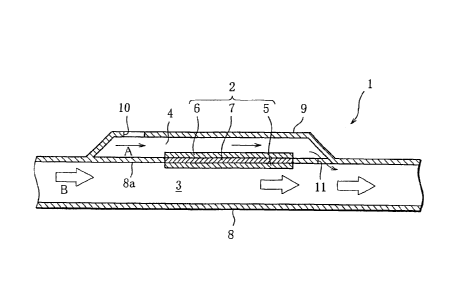
[00141 As illustrated in FIG. 1, an electricity
generation device 1 according to the present invention
includes a fuel cell 2, a fuel gas conduit 3, and an air
passage 4. The fuel cell 2 has a fuel electrode 5, an air
electrode 6, and an electrolyte 7 sandwiched between the
electrodes 5 and 6 in close contact therewith. The fuel
CA 02792791 2012-09-11
electrode 5 is exposed to the internal space of the fuel
gas conduit 3 and is supplied with a fuel gas flowing
through the fuel gas conduit 3 in a direction indicated by
arrows B. The air electrode 6 is exposed to the internal
5 space of the air passage 4 and is supplied with air flowing
through the air passage 4 in a direction indicated by
arrows A. Thus, the air electrode 6 reduces oxygen
contained in air, and the reduced oxygen ions pass through
the electrolyte 7 and react, at the fuel electrode 5, with
hydrogen contained in the exhaust gas, thus producing
water. Electrons produced at the fuel electrode 5 at this
time move through a circuit (not shown) and again ionize
oxygen at the air electrode 6, so that electric current
flows through the circuit, generating electricity. The
electrolyte 7 is, for example, a solid oxide, and in this
case, the fuel cell 2 is a solid oxide fuel cell (SOFC).
Especially in the case of using exhaust gas as the fuel
gas, an SOFC is preferably used because the SOFC withstands
high temperature, requires no catalyst, and can be reduced
in size because of its high output density. Also, where
exhaust gas is used as the fuel gas, a fuel reforming
material (not shown) is preferably arranged in the fuel gas
conduit 3 at a location upstream of the fuel electrode 5.
The fuel reforming material is used for converting
hydrocarbons, water and the like, contained in the exhaust
gas, into hydrogen to increase the concentration of
hydrogen.
[0015] The fuel gas conduit 3 is formed by a hollow
cylindrical inner pipe B. The air passage 4 is separated
from the fuel gas conduit 3 by a peripheral wall 8a of the
inner pipe 8 and is surrounded by a cover 9 covering part
of the peripheral wall 8a. That is, the air passage 4 is
formed by the peripheral wall 8a and the cover 9. An air
CA 02792791 2012-09-11
6
inlet hole 10 is formed through the cover 9 to allow air to
be introduced into the air passage 4. Accordingly, the air
inlet hole 10 serves as an upstream end of the air passage
4. An air outlet hole 11 is formed through that portion of
the inner pipe 8 which is located downstream of the air
electrode 6 exposed to the air passage 4 (in the figure, at
the downstream end of the air passage 4), to cause the air
passage 4 and the fuel gas conduit 3 to communicate with
each other.
[0016] Thus, the air outlet hole 11 communicating with
the fuel gas conduit 3 is provided at the downstream side
of the air passage 4, and accordingly, when the fuel gas is
flowing at high speed through the fuel gas conduit 3,
negative pressure is generated via the air outlet hole 11,
so that the air in the air passage 4 flows out into the
fuel gas conduit 3. As a result, a unidirectional flow of
air is created in the air passage 4, and since air can be
efficiently supplied to the air electrode 6, electricity
generation efficiency can be improved. Also, the flow of
air created by making use of the negative pressure is
gentle, and therefore, the fuel gas is not cooled by the
air, enabling electricity generation at high temperatures.
Consequently, the electricity generation efficiency can be
further improved. Although the flow of air is gentle, air
contains about 21% oxygen, and accordingly, no problem
arises in respect of the amount of oxygen supplied to the
air electrode 6. Also, where the exhaust gas of a motor
vehicle is used as the fuel gas, a considerably high flow
velocity of the exhaust gas makes it easier to create the
flow of air by the negative pressure generated via the air
outlet hole 11. In this case, the fuel electrode 5 is
supplied with hydrocarbons and the like contained in the
exhaust gas.
CA 02792791 2012-09-11
7
[0017] As illustrated in FIG. 2, the cover 9 may
alternatively be a hollow cylindrical member having a
larger diameter than the inner pipe 8 so that the cover 9
and the inner pipe 8 may constitute a double pipe structure
of what is called a tube type electricity generation
device. In this case, the cover 9 serves as an outer pipe
surrounding the inner pipe 8. The air passage 4 is defined
between the inner and outer pipes 8 and 9 and has opposite
ends closed by respective lids 13. The lid 13 located at
the downstream side of the air passage 4 has air outlet
holes 11 penetrating therethrough in the longitudinal
direction of the pipes 8 and 9. The tube type electricity
generation device 1 having such a double pipe structure is
arranged in an intermediate portion of a fuel gas pipe 12
through which the fuel gas flows. That is, the fuel gas
conduit 3 is formed by the inner pipe 8 and the upstream-
and downstream-side fuel gas pipes 12 continuous with the
inner pipe 8 and extending from the respective opposite
ends of the inner pipe 8. The outer pipe 9 is fixed at its
opposite ends to the respective fuel gas pipes 12. In the
illustrated example, the fuel electrode 5 serves also as
the inner pipe 8. That is, the fuel electrode 5 has a
hollow cylindrical shape so as to form the fuel gas conduit
3. A central hole 13a formed through each annular lid 13
also forms part of the inner pipe 8.
[0018] In this manner, the double pipe structure is
employed which is constituted by the inner pipe 8 for
passing the fuel gas and the outer pipe 9 for passing air,
and therefore, the electricity generation device as a whole
can be made compact in size. Also, since the outer pipe 9
is fixed to the fuel gas pipes 12 located upstream and
downstream thereof as viewed in the flowing direction of
the fuel gas, the material of the outer pipe 9 may be
CA 02792791 2012-09-11
8
selected taking account only of strength. A suitable
material can therefore be selected for the outer pipe 9 so
as to prevent deterioration with use. For example, metal,
high-strength ceramic or the like may be used as the
material of the outer pipe 9. Also, the outer pipe (cover)
9 may have a plurality of air inlet holes 10 formed
therethrough. This permits a larger amount of air to be
introduced into the air passage 4, making it possible
efficiently supply air to the air electrode 6.
Explanation of Reference Signs
[0019]
1 electricity generation device
2 fuel cell
3 fuel gas conduit
4 air passage
5 fuel electrode
6 air electrode
7 electrolyte
8 inner pipe
8a peripheral wall
9 cover (outer pipe)
10 air inlet hole
11 air outlet hole
12 fuel gas pipe
13 lid
13a central hole