Note: Descriptions are shown in the official language in which they were submitted.
CA 02792908 2012-10-22
1 SENSOR MOUNTING ASSEMBLY FOR DRILL COLLAR
2 STABILIZER
3
4 FIELD OF THE INVENTION
Embodiments of the invention relate to drilling tools having a sensor
6 and stabilizer arrangement allowing a sensor to be mounted having a
consistent
7 standoff independent of a size of a stabilizer, borehole or collar involved.
8
9 BACKGROUND
Fig. 1 shows the general configuration of a drilling system in a
11 Measurement-While-Drilling (MWD) or Logging-While-Drilling (LWD)
environment.
12 A downhole tool 10 disposes in a borehole BH and is operationally connected
to a
13 drill string 12 by a suitable connector 14. At its lower end, the tool 10
has a drill bit
14 16. Uphole, a rotary drilling rig 60 rotates the drill string 12, the
downhole tool 10,
and the drill bit 16 to drill the borehole BH. As will be appreciated, other
types of
16 borehole conveyance can be used for the downhole tool 10.
17 The downhole tool 10 has a drill collar 20, a borehole sensor 50, and
18 an electronics subsection 52. The drill collar 20 has a stabilizer sleeve
30 disposed
19 thereon, and the borehole sensor 50 is mounted at a stabilizer blade 32.
Depending on the desired parameters of interest, the borehole sensor 50
measures
21 data in the borehole environs, and the electronics subsection 52 can
process and
22 store the data and can telemeter the data uphole for any of the various
purposes
23 associated with LWD/MWD.
24
1
CA 02792908 2012-10-22
1 A surface processor 64 cooperating with the electronic
subsection 52
2 may handle the data and can perform additional mathematical operations
3 associated with standard geological applications. Processed data can then
be
4 output to a recorder 66 for storage and optionally for output as a
function of
measured depth thereby forming an "image" or "log" 68 of one or more
parameters
6 of interest. All throughout operations, signals can be sent downhole to
vary the
7 direction of drilling or to vary the operation of the downhole tool 10.
8 There are a few techniques for mounting a sensor on a
downhole tool
9 10 for interaction with a borehole BH. Conventional wisdom in the art has
been to
either install the sensor externally on a drill collar or stabilizer or to
particularly
11 configure the sensor to install on the drill collar or stabilizer. Thus,
one technique
12 simply mounts a sensor with a plate on a portion of a drill collar. For
example, U.S.
13 Pat. No. 7,250,768 to Ritter et al. discloses a modular cross-over sub
for a bottom
14 hole drilling assembly having a stabilizer. Separate from the stabilizer,
a resistivity
sensor on a plate affixes to the outside of the sub where the sensor and
measuring
16 electronics are disposed.
17 Alternatively, a sensor can be directly part of a
stabilizer. For
18 example, U.S. Pat. Pub. No. 2009/0025982 discloses instrumentation devices
19 disposed externally on a blade of a stabilizer using rings attached to
the blade with
screws or other attachment means.
21 Finally, a particularized package for a sensor can fit in a
recess of a
22 downhole tool and can have a stabilizer fit thereover. For example, U.S.
Pat. No.
23 6,666,285 to Jones et al. discloses a drilling conduit having a cavity
particularly
2
CA 02792908 2012-10-22
1 sized to receive an instrument package. A portion of the package radially
protrudes
2 a distance, and an alignment channel in a stabilizer element is dimensioned
to
3 receive the protruding portion of the instrument package. For ease of
4 manufacturing, the alignment channel extends the entire length of the
stabilizer
element.
6 As a particular example, Fig. 2 is a side cross-section of a portion
of a
7 downhole tool 10 having a sensor and stabilizer arrangement according to the
prior
8 art. The drill collar 20 is shown with its internal bore 22 for passage of
drilling fluid.
9 A sensor housing 40 fits inside a recess or pocket 24 formed on the outside
surface
23 of the drill collar 20 and hard-mounts to the drill collar 20 using
mounting
11 components 42. The sensor housing 40 has a sensor 50 (e.g., LWD downhole
12 measurement equipment), and the hard mounting of the housing 40 provides
stable
13 positioning of the sensor 50 and helps protect the sensor 50 from damage.
14 The sensors used for LWD/MWD applications typically measure
parameters of the formation traversed by the borehole or of the borehole
itself. In
16 typical applications, measurement accuracy is degraded by excessive and/or
17 inconsistent standoff between the sensor and the surrounding borehole wall.
To
18 reduce standoff, the sensor 50 may actually be positioned in the drill
collar's pocket
19 24 at a further radial distance than the drill collar's outer surface 23.
This allows the
sensor 50 to position closer to the borehole wall. To help maintain the
consistent
21 standoff and to protect the sensor 50, a stabilizer sleeve 30 is typically
employed
22 and is positioned directly on the drill collar's outer surface 23. When the
sleeve 30
23 is pushed into position on the outside of the drill collar 20, one of the
stabilizer
3
CA 02792908 2012-10-22
1 blades 32 on the stabilizer sleeve 30 fits directly over the sensor
housing 40, and
2 the stabilizer sleeve 30 can be retained using a shoulder on the drill
collar 20 and a
3 bushing 34 or other features.
4 Because the housing 40 is physically mounted to the collar 20,
the
distance between the sensor 50 and the borehole wall will change if the
diameter of
6 the borehole BH to be drilled is changed and if the stabilizer sleeve's
diameter is
7 also changed accordingly. This impacts the ability to make consistent
8 measurements with the sensor 50 when used in different configurations
because
9 the changes in distance from the borehole wall will attenuate the
measurements
made.
11 For example, Figs. 3A-3B are end views diagramming the prior
art
12 sensor and stabilizer arrangement for different sized boreholes BH1 and
BH2. As
13 can be seen, the radius R1 of the first borehole BFli is smaller than the
radius R2 of
14 the second borehole BH2. As is common, the same sized drill collar 20 may
be
used to drill both of these boreholes BH1 and BH2, while other components of
the
16 drilling system are changed to create the different sized boreholes BH1
and BH2.
17 To account for the difference in borehole size relative to the same sized
drill collar
18 20, different sized stabilizer sleeves 301 and 302 are used when
drilling. For
19 instance, the first stabilizer sleeve 301 for the smaller borehole BH1
has lower profile
stabilizer blades 321, while the other stabilizer sleeve 302 for the larger
borehole
21 BH2 has higher profile stabilizer blades 322.
22 Yet, in both circumstances, the sensor housing 40 hard-mounted
to
23 the drill collar 20 keeps the sensor 50 at the same position on the drill
collar 20. As
4
CA 02792908 2012-10-22
1 a result, the sensor 50 has a smaller standoff Si relative to the wall of
the smaller
2 borehole BHI, but has a larger standoff S2 relative to the wall of the
larger borehole
3 BH2.
4 For measurement accuracy, the sensor 50 is typically calibrated
electronically and with processing algorithms to operate best with a
particular
6 standoff from the borehole wall. Due to the different sized stabilizer
sleeves 301
7 and 302 needed in some drilling applications as seen in Figs. 3A-3B, the
standoff
8 under which the sensor 50 measures can change. To obtain useful
measurements,
9 operators must therefore recalibrate the sensor 50 to operate with the
different
standoffs Si and S2, or an entirely different sensor housing 40 may need to be
used
11 so the sensor 50 will have the calibrated standoff.
12 As always, changes or modifications made in drilling applications can
13 increase costs, slow down drilling operations, engender unwanted errors,
and the
14 like. For these and other reasons, the subject matter of the present
disclosure is
directed to overcoming, or at least reducing the effects of, one or more of
the
16 problems set forth above.
17
18 SUMMARY
19 A sensor and stabilizer arrangement for a borehole drilling tool
allows
a sensor to be mounted with the same standoff from a borehole wall independent
of
21 the size of stabilizer, borehole, and collar involved. The drilling tool
has a drilling
22 body, such as a drill collar, defining a receptacle exposed in its outer
surface. An
23 electronic sensor component for an LWD/MWD-type sensor or detector disposes
in
5
CA 02792908 2012-10-22
1 the receptacle, but does not affix in the receptacle. Instead, a
stabilizer fits over the
2 drill collar and covers the receptacle and sensor component, and the sensor
3 component mounts directly to the underside of the stabilizer. For example,
4 fasteners affix in openings on the outside surface of the stabilizer and
mount the
sensor component directly to the underside of the stabilizer so that the
electronic
6 component "floats" or "suspends" in the receptacle. Preferably, the sensor
7 component mounts directly to the stabilizer's underside at one of the
stabilizer
8 blades so a sensor element exposed on the outside of the stabilizer can be
9 positioned in proximity to the borehole wall to measure parameters of
interest.
The drill collar and sensor component can be used in different sized
11 boreholes during drilling, and different sized stabilizer may be
positioned on the drill
12 collar to account for the different sized boreholes. Thus, the disclosed
arrangement
13 offers a modular system in which the same sensor component and drill
collar can be
14 used together and different sized stabilizers can be interchanged thereon
depending on the borehole size. Because the same sized drill collar and sensor
16 components may be used to drill larger or smaller sized boreholes, having
the
17 sensor component mounted directly underneath the stabilizer maintains the
same
18 standoff between the sensor and the borehole wall regardless of the
borehole size
19 being drilled. Thus, operators can use the same sensor components for
different
sized boreholes and do not need to reconfigure or recalibrate the sensor to
operate
21 with a different standoff in different sized boreholes.
22 The disclosed stabilizer and sensor arrangement is in
contrast to the
23 typical hard-mounting of sensor components to the drill collar in the
prior art. Being
6
CA 02792908 2012-10-22
1 coupled to the stabilizer, the sensor maintains a consistent standoff from
the
2 borehole wall, and the sensor can be calibrated to obtain the best
measurements
3 with this particular standoff. The disclosed arrangement can offer a number
of
4 benefits in the operation of a drilling tool having a sensor because the
arrangement
maintains a consistent distance between the borehole wall and any sensors,
6 independent of tool body size, stabilizer size, or borehole size. As a
result, there
7 will be less measurement attenuation in comparison to the current collar
mounted
8 scheme.
9 The foregoing summary is not intended to summarize each potential
embodiment or every aspect of the present disclosure.
11
12 BRIEF DESCRIPTION OF THE DRAWINGS
13 Figure 1 illustrates a drilling assembly having a sensor mounted on a
14 stabilizer of a downhole tool;
Figure 2 is a side cross-section of a downhole tool having a sensor
16 and stabilizer arrangement according to the prior art;
17 Figures 3A-3B are end views showing the prior art sensor and
18 stabilizer arrangement for different sized boreholes
19 Figure 4 is a side cross-section showing a downhole tool having a
sensor and stabilizer arrangement according to the present disclosure;
21 Figure 5A is an end view of the downhole tool of Fig. 4;
22 Figures 5B-5C are end-sections of the downhole tool of Fig. 4;
23 Figure 6A is a plan view of a drill collar for the disclosed sensor
and
7
CA 02792908 2012-10-22
1 stabilizer arrangement;
2 Figure 6B-1 is a plan view of a sensor housing for the disclosed
3 sensor and stabilizer arrangement;
4 Figure 6B-2 is an end view of the sensor housing of Fig. 6B-1;
Figure 6C is a plan view of a stabilizer for the disclosed sensor and
6 stabilizer arrangement;
7 Figures 7A-7B are end views diagramming the disclosed sensor and
8 stabilizer arrangement for different sized boreholes;
9 Figure 8 is an end-section detailing the stabilizer, the sensor
housing,
and other components; and
11 Figures 9A-9B are end-sections showing pressure forces acting on the
12 sensor housing and sensor element.
13
14 DETAILED DESCRIPTION
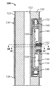
Fig. 4 is a side cross-section showing a downhole tool 100 having a
16 sensor and stabilizer arrangement according to the present disclosure. The
tool
17 100 can be used on a drilling assembly, such as discussed previously in
Fig. 1. The
18 tool 100 includes a downhole tubular 120, such as a drill collar or other
drilling body.
19 The drill collar 120 carries a sensor component, which includes a sensor
housing
140 and sensor 150 for MWD/LWD applications in a borehole. As is customary,
the
21 drill collar 120 can have an internal bore 122 for passage of drilling
fluid and can
22 have an outside surface 123 with a protective sheathing.
23
8
CA 02792908 2012-10-22
1 The tool's sensor housing 140 disposes in a receptacle or pocket 124
2 formed on the outer surface 123 of the drill collar 120. The sensor housing
140
3 holds the borehole sensor 150 beyond the collar's outer surface 123 so the
sensor
4 150 can be positioned in closer proximity to a borehole wall (not shown) for
measuring parameters of interest. As will be appreciated, the sensor 150 can
be
6 any LWD/MWD sensor, detector, or other device used in the art, including,
but not
7 limited to, a resistivity imager, a gamma sensor, an extendable formation
testing
8 sensor, a transducer, a transceiver, a receiver, a transmitter, acoustic
element, etc.
9 To provide strength and to reduce electrical interference, the sensor
housing 140
can be made from a suitable alloy.
11 The drill collar 120 has a stabilizer 130 disposed thereon to
stabilize
12 the drill collar 120 during operation and to position the sensor 150 closer
to the
13 borehole wall. Although not shown, the stabilizer 130 can affix to the
drill collar 120
14 using any of the common techniques known in the art. For example, the
stabilizer
130 can be heat shrunk onto the collar 120, and/or ends 136 of the stabilizer
130
16 can be affixed by welding, fasteners, or the like.
17 Rather than hard-mounting the sensor housing 140 to the drill collar
18 120 as in the prior art, the sensor housing 140 mounts directly to the
underside or
19 undersurface 134 of the stabilizer 130 and preferably mounts at one of the
extended
stabilizer blades 132. By mounting directly to the undersurface 134, the
sensor
21 housing 140 is essentially supported at its circumferential distance on the
drill collar
22 120 independent of the receptacle 124. Accordingly, the housing 140
"floats" or
23 "suspends" in the drill collar's receptacle 124. As shown in Figure 4, for
example,
9
CA 02792908 2012-10-22
1 the sensor housing 140 is shown disposed in, but not mounted in, the sensor
2 receptacle 124 of the drill collar 120. A top surface 146 of the sensor
housing 140
3 mounts directly to the undersurface 134 of the stabilizer 130 so that
sensor
4 openings in the housing 140 align with corresponding openings in the
stabilizer 130.
If desired, support (i.e., shims, spacers, shock absorbers, etc.) can be used
in the
6 space between the sensor housing 140 and the receptacle 124.
7 The sensor housing 140 has a central passage or compartment 144 in
8 which electronic components 154 of the sensor 150 mount. Typically, the
electronic
9 components 154 include a circuit board, power supply, and other elements
needed
for operation of the sensor 150. The internal components 154 can operatively
11 couple to one or more external sensor elements 152 exposed on the surface
of the
12 stabilizer 150, but this depends on the sensor 150 used as some sensors may
not
13 require such an exposed element 152. The sensor element 152 is intended to
14 interact with the borehole wall, annulus, etc. to obtain measurements of
interest.
End caps 148 affix to open ends of the housing 140 to seal the
16 housing's compartment 144 so the electronic components 154 can be protected
17 from pressures and drilling fluid. These end caps 148 can have passages to
18 communicate electric wiring, hydraulics, or the like between the sensor
components
19 154 and other parts of the tool 100, such as memory or telemetry
components.
Fig. 5A is an end view of the drill collar 120, showing the arrangement
21 of the stabilizer 130 and blades 132 about the collar's outer surface 123.
The end-
22 section of Fig. 5B shows the sensor housing 140 disposed in the collar's
receptacle
23 124 and abutted against the undersurface 134 of the stabilizer 130 at one
of the
10
CA 02792908 2012-10-22
1 blades 132. The sensor element 152 is shown exposed on the surface of the
blade
2 132 and extending into the housing's compartment 144 where the sensor
element
3 152 operatively couples to the electronic components 154.
4 Finally, the end-section of Fig. 5C shows the sensor housing 140
mounted directly to (i.e., directly attached or affixed to) the collar's
undersurface 134
6 using fasteners 160. Although one of the blades 132 has a sensor housing 140
and
7 sensor 150 as detailed herein, one or more of the other blades 132 could
also have
8 such components. Moreover, although preferred, the sensor component (i.e.,
9 housing 140 and sensor 150) need not be disposed at a blade, if any, on the
stabilizer 130.
11 With a general understanding of the stabilizer and sensor
12 arrangement, assembly of the disclosed arrangement is discussed with
reference to
13 Figs. 6A through 6C. As shown in the plan view of Fig. 6A, the drill collar
120 has
14 its receptacle 124 formed in its outer surface 123 using conventional
techniques.
Various channels or passages (not shown) may be defined in the collar 120 to
16 communicate electronic wiring, hydraulics, and the like to any components
to be
17 held in the receptacle 124. As noted herein, the sensor housing 140 does
not
18 mount to the drill collar 120 so fastening holes may not be present,
although various
19 alignment holes (not shown) may be provided in the receptacle's bottom
surface to
receive alignment pins or the like so the housing 140 can be aligned in the
21 receptacle 124.
22 The sensor housing 140 is a pressure housing, and as shown in
23 Figs. 6B-1 and 6B-2, the housing 140 can have an elongated, cylindrical
body 142,
11
CA 02792908 2012-10-22
1 although other shapes such as rectilinear shapes can be used. The body 142
2 defines the internal compartment 144 for electronics and has one or more
mounting
3 surfaces or platforms 146 with fastener holes 147, alignment pin holes, and
sensor
4 holes 145 for aligning with holes in the stabilizer 130 as discussed below.
Although
alignment can be achieved in a number of ways between the components,
6 alignment for the housing 140 is preferably accomplished using pins (not
shown)
7 between the sensor housing 140 and the stabilizer 130.
8 As shown in Fig. 6C and elsewhere, the stabilizer 130 is typically a
9 cylindrical sleeve and has a number of outward extending blades 132, ribs,
arms, or
other features that increase the outer dimension of the stabilizer 130. The
stabilizer
11 130 fits over the drill collar 120 and mounts thereon using techniques
known in the
12 art, such as heat shrinking, welding, bolting, and the like. The stabilizer
130 has a
13 number of holes or openings defined in one of the blades 132 or elsewhere,
14 including sensor openings 135 for portions of the sensor 150 to face the
borehole
environs. Other openings 137 are mounting pin holes to receive mounting bolts
or
16 fasteners (160) to hold the sensor housing 140 underneath the stabilizer
130, as
17 discussed previously.
18 During assembly, the sensor housing 140 is outfitted with the
19 components and electronics of the sensor 150, end caps 148, etc. Assemblers
then
set the housing 140 temporarily in the collar's receptacle 124. Assemblers
then
21 slide the stabilizer 130 shown in Fig. 6C over the drill collar's outer
surface 123
22 while the sensor housing 140 rests in the receptacle 124. When properly
23 positioned, assemblers then position fasteners 160 through openings 137 in
the
12
CA 02792908 2012-10-22
1 stabilizer 130 to affix to the fastener holes 147 on the housing's mounting
surface
2 146. As the fasteners are tightened, the sensor housing 140 "floats" or
"suspends"
3 in the collar's receptacle 124 and mounts directly to the underside of the
stabilizer
4 130. The sensor element 152 can then be installed as needed into the sensor
openings 135 in the stabilizer 130 to connect with the electronic components
154
6 installed in the housing 140 underneath.
7 The advantages of the sensor and stabilizer arrangement of the
8 present disclosure are best illustrated with reference to Figs. 7A-76, which
show the
9 disclosed sensor and stabilizer arrangement for different sized boreholes.
As can
be seen, the radius R1 of a first borehole 61-11 (Fig. 7A) is smaller than the
radius R2
11 of a second borehole BH2 (Fig. 7B). Again, the same sized drill collar 120
may be
12 used in some circumstances to drill both of these boreholes 61-11 and BH2
because
13 other components of the drilling assembly may be changed to create the
different
14 sized boreholes 61-11 and BH2.
To account for the difference in borehole size relative to the same
16 sized drill collar 120, different sized stabilizers 1301and 1302 are used
when drilling.
17 The first stabilizer 1301 (Fig. 7A) for the smaller borehole BI-11 has
lower profile
18 stabilizer blades 1321, while the other stabilizer 1302 (Fig. 7B) for the
larger
19 borehole BH2 has higher profile stabilizer blades 1322.
Yet, in both circumstances, the sensor housing 140 mounted to the
21 undersurface 134 of the stabilizer 130 keeps the sensor 150 at similar
standoffs S3
22 and S4 from the borehole wall. The similar standoffs S3 and S4 are
preferably the
23 same, although they may vary to some degree dependent on the sensitivity
and
13
CA 02792908 2012-10-22
1 calibration of the sensor 150. Having the similar standoffs S3 and S4 is
possible
2 because the sensor housing 140 "floats" or "suspends" in the collar's
receptacle 124
3 as noted above and sits at different radii R3 and R4, respectively, for the
different
4 sized boreholes BH1 and BH2.
As noted previously, the sensor 150 is calibrated electronically with
6 processing algorithms to operate best with a particular standoff from the
borehole
7 wall. Using the disclosed arrangement, the particular standoff S for the
sensor 150
8 can be maintained despite the different sized stabilizers 1301 and 1302
needed in
9 some drilling applications. Accordingly, operators do not need to
recalibrate the
sensor 150 to operate with a different standoff and do not need to use an
entirely
11 different sensor as required in the prior art. Thus, the disclosed
arrangement offers
12 a modular system in which the same component, including sensor 150 and
housing
13 140, and the same drill collar 120 can be used together and in which
different sized
14 stabilizers 1301 and 1302 can be interchanged on the drill collar 120
depending on
the borehole size.
16 In addition to the above, there are other advantages of the disclosed
17 sensor and stabilizer arrangement. Fig. 8 shows a detailed end-section of
the
18 sensor housing 140 mounted on the underside 134 of the stabilizer 130. As
noted
19 before, the sensor housing 140 is disposed in the collar's receptacle 124,
and the
housing's mounting surface 146 is abutted against the undersurface 134 of the
21 stabilizer 130 at one of the blades 132.
22 The sensor element 152 is installed in the sensor opening 135 of the
23 blade 132 and extends down into the sensor opening 145 in the sensor
housing
14
CA 02792908 2012-10-22
1 140. Various features, such as fasteners, threads, bushings, welds, etc.
are not
2 shown, but can be used to retain the sensor component 150 in these openings
135
3 and 145. In addition to (or as an alternative to) such features, one or
more sealing
4 members 170 can be disposed between the interface of the sensor component
150
and the housing's opening 145. Thus, the sensor element 152 is exposed on the
6 surface of the blade 132 and extends into the housing's sealed compartment
144
7 where the element 152 operatively couples to the electronic components 154.
8 When the drill collar 120 is deployed downhole in a borehole, fluid
9 pressure Fp from the borehole as shown in Fig. 9A may enter inside the
drill collar's
sensor receptacle 124, depending on the sealing used. In turn, the fluid
pressure Fp
11 in the receptacle 124 acts against the surfaces of the housing 140, and the
net force
12 of this fluid pressure Fp preferably forces the housing's mounting surface
146
13 against the undersurface 134 of the stabilizer 130. Overall, the force of
this fluid
14 pressure Fp can help hold the sensor housing 140 in place on the
stabilizer's
undersurface 134.
16 As shown in Fig. 9B, fluid pressure Fp in the borehole annulus also
17 acts against the surfaces of the sensor element 152 outside the sealing
members
18 170 used. The net force of the fluid pressure Fp preferably tends to hold
the sensor
19 element 152 in the stabilizer blade 132 and housing 140. As noted
previously, the
interior compartment 144 of the housing 140 is preferably fluidly isolated
from the
21 borehole so the electronic components 154 can be protected. The sealing
22 members 170 used in the opening 145 help isolate the components 154 from
fluid
23 and help to keep the housing's interior compartment 144 at a lower pressure
(e.g.,
15
CA 02792908 2012-10-22
1 atmospheric) than the borehole annulus. Advantageously, this difference in
2 pressure between the upper and lower ends of the sensor element 152 tends to
3 further retain the element 152 in the openings 135 and 145 of the blade 132
and
4 housing 140.
The foregoing description of preferred and other embodiments is not
6 intended to limit or restrict the scope or applicability of the inventive
concepts
7 conceived of by the Applicants. It will be appreciated with the benefit of
the present
8 disclosure that features described above in accordance with any embodiment
or
9 aspect of the disclosed subject matter can be utilized, either alone or in
combination, with any other described feature, in any other embodiment or
aspect
11 of the disclosed subject matter.
12
16