Language selection

Search

Patent 2793384 Summary

Third-party information liability

Some of the information on this Web page has been provided by external sources. The Government of Canada is not responsible for the accuracy, reliability or currency of the information supplied by external sources. Users wishing to rely upon this information should consult directly with the source of the information. Content provided by external sources is not subject to official languages, privacy and accessibility requirements.

Claims and Abstract availability

Any discrepancies in the text and image of the Claims and Abstract are due to differing posting times. Text of the Claims and Abstract are posted:

  • At the time the application is open to public inspection;
  • At the time of issue of the patent (grant).
(12) Patent: (11) CA 2793384
(54) English Title: SHELF SUPPORT FRAME
(54) French Title: CADRE D'APPUI POUR UNE ETAGERE
Status: Expired and beyond the Period of Reversal
Bibliographic Data
(51) International Patent Classification (IPC):
  • B65D 19/28 (2006.01)
  • B65G 1/02 (2006.01)
(72) Inventors :
  • BOHNACKER, ULRICH (Switzerland)
(73) Owners :
  • TEGOMETALL INTERNATIONAL AG
(71) Applicants :
  • TEGOMETALL INTERNATIONAL AG (Switzerland)
(74) Agent: KIRBY EADES GALE BAKER
(74) Associate agent:
(45) Issued: 2015-01-06
(86) PCT Filing Date: 2011-04-07
(87) Open to Public Inspection: 2011-10-13
Examination requested: 2012-09-17
Availability of licence: N/A
Dedicated to the Public: N/A
(25) Language of filing: English

Patent Cooperation Treaty (PCT): Yes
(86) PCT Filing Number: PCT/EP2011/001742
(87) International Publication Number: WO 2011124383
(85) National Entry: 2012-09-17

(30) Application Priority Data:
Application No. Country/Territory Date
20 2010 004 600.9 (Germany) 2010-04-07

Abstracts

English Abstract

A support frame to be laid on a pair of cross-members (16) of a rack has at least two U-section rails (12) and a plurality of C-section rails (11) running transversely thereto, of which the flanges (14) are joined to the central webs of the U-section rails (12). The distance between the U-section rails (12) of the support frame is dimensioned such that said rails fit exactly between the two cross-members (16) of the storage rack. The central webs of the C-section rails (11) are perforated, wherein at least some of the holes (17) have rims (18) projecting from the surface of the C-section rails (11), which faces away from the U-section rails (12).


French Abstract

L'invention concerne un cadre d'appui pour l'appui sur une paire de traverses (16) d'une étagère, qui comprend au moins deux rails en U (12) et plusieurs rails en C (11) disposés perpendiculairement à ceux-ci, dont les brides (14) sont reliées avec les barres centrales des rails en U (12). La distance entre les rails en U (12) du cadre d'appui est calculée de manière à ce qu'ils passent juste entre les deux traverses (16) de l'étagère. Les barres centrales des rails en C (11) sont perforées, au moins certains des orifices (17) comprenant des bords d'orifice (18) saillants sur la surface des rails en C (11) opposée aux rails en U (12).

Claims

Note: Claims are shown in the official language in which they were submitted.

4
Claims:
1. A combination of a storage shelf having vertical columns and cross-
members
connecting them, and a support frame comprising at least two U-profile bars
and a
plurality of C-profile bars extending transversely thereto and having flanges
connected to the centre webs of the U-profile bars, wherein the space between
the
U-profile bars of the support frame is so dimensioned that they just fit
between both
cross-members of the storage shelf.
2. The combination of claim 1, wherein the flanges of the C-profile bars
are
screwed to the centre webs of the U-profile bars.
3. The combination of claim 2, wherein at least some of the C-profile bars
have
both of their flanges screwed to the U-profile bars.
4. The combination of any one of claims 1 to 3, wherein die centre webs of
the
C-profile bars are perforated.
5. The combination of claim 4, wherein at least some of the holes have rims
protruding from the surface of the C-profile bars facing away from the U-
profile bars.
6. The combination of any one of claims 1 to 5, wherein the length of the C-
profile bars is greater than the space between the U-profile bars.
7. The combination of any one of claims 1 to 6, wherein the space between
two
C-profile bars is smaller near either end of the U-profile bars than in the
central area
of the support frame.

Description

Note: Descriptions are shown in the official language in which they were submitted.


CA 02793384 2014-02-26
_
1
SHELF SUPPORT FRAME
Field and Background
For supporting pallets in storage shelves, it is common to use bars extending
in the depth direction of the shelf, which bars are individually placed on
pairs of
cross-members of the shelf. If the pallets are not lowered onto the bars not
vertically
and with sufficient accuracy there is a danger for the bars to slip and fail
to support
the pallets properly.
DE 43 01 475 Al discloses a support structure for a storage shelf in which a
specifically constructed profile beam is fixedly connected to the shelf cross-
members to support pallets.
WO 2009/114256 Al discloses a pallet constructed of metal profile members.
Summary
Certain exemplary embodiments can provide a combination of a storage
shelf having vertical columns and cross-members connecting them, and a support
frame comprising at least two U-profile bars and a plurality of C-profile bars
extending transversely thereto and having flanges connected to the centre webs
of
the U-profile bars, wherein the space between the U-profile bars of the
support
frame is so dimensioned that they just fit between both cross-members of the
storage shelf.
The fixed connection of C-profile bars, which serve to support goods to be
stored, to U-profile bars extending perpendicularly thereto creates a unit
which can
be simply laid on the shelf cross-members and, if the spacing between the U-
profile
bars is properly selected, results in an arrangement of the C-profile bars
which
practically cannot move in the depth direction of the shelf.
In another embodiment, the support frame may be assembled at the site,
thereby reducing transportation expenditure. Another feature prevents the
frame
from being distorted in a parallelogram manner.

CA 02793384 2014-02-26
2
Another feature not only results in a saving of material and weight but also
forms a safety measure. In another embodiment, slippage of the stored goods is
counteracted.
Another feature achieves a spatial fixation of the support frame, wherein the
C-profile bars supporting the stored goods do not extend beyond the given
depth of
the shelf.
Another feature has an advantage with respect to the stability of the support
frame in case a pallet is lowered in a tilted manner.
The combination with a shelf according to another feature ensures a stable
positioning of the support frame which does not slip in the depth direction of
the
shelf.
Brief description of the drawings
An embodiment of the invention will be explained in detail below with
reference to the drawings in which:
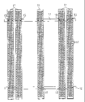
Fig. 1 a plan view of a support frame;
Fig. 2 a side view of the support frame taken from below in Fig. 1;
Fig. 3 a side view taken from the left in Fig. 1;
Fig. 4 an enlarged end view of a C-profile bar; and
Fig. 5 an enlarged cross-section of a part of the perforated C-profile bar.
Detailed description
The support frame shown in the drawings consists of a plurality, five in the
example shown, of C-profile bars 11 extending parallel to one another, and two
U-
profile bars 12 extending perpendicularly thereto. At the locations designated
by 13,
the mutually facing flanges 14 (Fig. 4) of the C-profile bars 11 are connected
by
means of screw bolts and nuts to the centre webs 15 of the U-profile bars 12
which
face upward in Fig. 2.

CA 02793384 2014-02-26
3
In the side view of Fig. 3, two cross-members 16 of a storage shelf are
shown in cross-section. The mutual spacing of the U-profile bars 12 of the
support
frame is so dimensioned that they come to lie inside the shelf cross-members
16 so
closely that they substantially prevent the support frame from moving in the
depth
direction of the shelf. At the same time, they ensure that the support frame
can be
placed onto cross-members 16 only in such a manner that the C-profile bars 11,
which serve to receive goods to be stored, specifically pallets, extend in the
depth
direction of the shelf and the overall frame is held in its plane with the
proper
angular orientation. In addition, the U-profile bars 12 determine the amount
by
which the C-profile bars 11 extend beyond the cross-members 16 in the depth
direction of the shelf, thereby ensuring that the C-profile bars 11 lie within
the space
available for the overall shelf.
In the embodiment shown in Figs. 1 and 2, two C-profile bars 11 are
disposed closely together near either end of the U-profile bars 12 whereas
there is a
greater spacing between the C-profile bars 11 in the central area of the
support
frame. Both lateral portions of the support frame are thereby given high
stability so
that, in case a pallet is lowered in a tilted manner, sufficient load-bearing
capacity is
available on the respective side of the support frame.
The centre webs of the C-profile bars 11 are provided with a plurality of
holes
17. The holes 17 not only reduce the material usage and weight of the support
frame but also provide fire a protection by passing sprinkler water.
As shown in Figs. 4 and 5, a part of the holes 17 are embossed upward to
form rims 18 protruding form the surface of the C-profile bars 11 facing away
from
the U-profile bars 12, which rims prevent or at least impede slippage of the
goods
stored on the support frame.

Representative Drawing
A single figure which represents the drawing illustrating the invention.
Administrative Status

2024-08-01:As part of the Next Generation Patents (NGP) transition, the Canadian Patents Database (CPD) now contains a more detailed Event History, which replicates the Event Log of our new back-office solution.

Please note that "Inactive:" events refers to events no longer in use in our new back-office solution.

For a clearer understanding of the status of the application/patent presented on this page, the site Disclaimer , as well as the definitions for Patent , Event History , Maintenance Fee  and Payment History  should be consulted.

Event History

Description Date
Time Limit for Reversal Expired 2017-04-07
Letter Sent 2016-04-07
Grant by Issuance 2015-01-06
Inactive: Cover page published 2015-01-05
Inactive: Final fee received 2014-10-20
Pre-grant 2014-10-20
Notice of Allowance is Issued 2014-04-28
Letter Sent 2014-04-28
Notice of Allowance is Issued 2014-04-28
Inactive: Q2 passed 2014-04-24
Inactive: Approved for allowance (AFA) 2014-04-24
Amendment Received - Voluntary Amendment 2014-02-26
Inactive: S.30(2) Rules - Examiner requisition 2013-12-30
Inactive: Report - No QC 2013-12-20
Inactive: Cover page published 2012-11-14
Inactive: Acknowledgment of national entry - RFE 2012-11-08
Inactive: Applicant deleted 2012-11-08
Inactive: IPC assigned 2012-11-08
Application Received - PCT 2012-11-08
Inactive: First IPC assigned 2012-11-08
Letter Sent 2012-11-08
National Entry Requirements Determined Compliant 2012-09-17
Request for Examination Requirements Determined Compliant 2012-09-17
All Requirements for Examination Determined Compliant 2012-09-17
Application Published (Open to Public Inspection) 2011-10-13

Abandonment History

There is no abandonment history.

Maintenance Fee

The last payment was received on 2014-02-19

Note : If the full payment has not been received on or before the date indicated, a further fee may be required which may be one of the following

  • the reinstatement fee;
  • the late payment fee; or
  • additional fee to reverse deemed expiry.

Please refer to the CIPO Patent Fees web page to see all current fee amounts.

Fee History

Fee Type Anniversary Year Due Date Paid Date
Request for examination - standard 2012-09-17
Basic national fee - standard 2012-09-17
MF (application, 2nd anniv.) - standard 02 2013-04-08 2013-03-19
MF (application, 3rd anniv.) - standard 03 2014-04-07 2014-02-19
Final fee - standard 2014-10-20
MF (patent, 4th anniv.) - standard 2015-04-07 2015-03-30
Owners on Record

Note: Records showing the ownership history in alphabetical order.

Current Owners on Record
TEGOMETALL INTERNATIONAL AG
Past Owners on Record
ULRICH BOHNACKER
Past Owners that do not appear in the "Owners on Record" listing will appear in other documentation within the application.
Documents

To view selected files, please enter reCAPTCHA code :


To view images, click a link in the Document Description column. To download the documents, select one or more checkboxes in the first column and then click the "Download Selected in PDF format (Zip Archive)" or the "Download Selected as Single PDF" button.

List of published and non-published patent-specific documents on the CPD .

If you have any difficulty accessing content, you can call the Client Service Centre at 1-866-997-1936 or send them an e-mail at CIPO Client Service Centre.


Document
Description 
Date
(yyyy-mm-dd) 
Number of pages   Size of Image (KB) 
Description 2014-02-26 3 118
Claims 2014-02-26 1 30
Claims 2012-09-17 1 35
Description 2012-09-17 3 111
Drawings 2012-09-17 2 53
Abstract 2012-09-17 1 15
Representative drawing 2012-11-09 1 23
Cover Page 2012-11-14 2 59
Representative drawing 2014-12-17 1 27
Cover Page 2014-12-17 1 56
Acknowledgement of Request for Examination 2012-11-08 1 175
Notice of National Entry 2012-11-08 1 201
Reminder of maintenance fee due 2012-12-10 1 113
Commissioner's Notice - Application Found Allowable 2014-04-28 1 161
Maintenance Fee Notice 2016-05-19 1 170
PCT 2012-09-17 5 173
Correspondence 2014-10-20 1 37