Note: Descriptions are shown in the official language in which they were submitted.
CA 02793387 2012-09-17
Optical sensor cable for use in measurements in UV light
and for use during irradiation processes
The invention relates to an optical sensor cable designed as a flat ribbon
cable which is
intended for use in measurements in UV light and for use during UV light
irradiation processes.
Optical cables are widely known, though their cross-sections are usually
designed
circularly (to name an example: DE 92 17 037 U1). A fibre-optic sensor cable
which is designed as
a flat ribbon cable is known (DE 2600100 Al). Such cable has a different
rigidity for both
directions of the transverse dimension; it especially has a higher flexibility
for bends around an
axis of the smaller transverse dimension compared to bends around an axis of
the larger
transverse dimension.
Another optical sensor cable is described in US 6 459 087 B1. It serves to
measure the
intensity of an UV emitter with two or more paired fibre-optic cables which
are each enclosed by
an edged glass filter and which are covered by a common transparent coating.
When the sensor
cable is used it is positioned alongside the UV emitter wherein the length of
the sensor cable
corresponds to the length of the UV emitter. The light of the UV emitter to be
measured
penetrates the transparent coating and the edged glass filters and into the
fibre-optic cables
where the latter cables have been doped in a way that enables the light
transmission to
preferably take place in the blue spectral range in the longitudinal direction
of the cable.
A method for repairing pipe or channel systems is the so-called pipe lining
method (e.g.
EP 0712352 131, EP 1262708 Al, or WO 2006061129). Flexible tube supports made
of stainless
synthetic and/or glass-fibres which are saturated with reactive resin moulding
compound are
used. The fitting into a channel is usually performed by installing the tube
(liner) either by
inversion (plugging in) by means of hydrostatic pressure or air pressure and
pulling the tube in by
means of a cable winch and subsequently mounting the tube using air or water
pressure or a
combination of both. There are two methods for hardening the liner to become a
solid plastic
pipe: artificial ageing by means of hot water or steam, and UV light curing
(UVA or LED
technology).
The control process for the light curing technique is described in EP 0122 246
Al. The
temperature is measured at different points of the string of lights (inner
surface of the lining) and
the airflow and the modulation rate of the light source are controlled.
Another documentation
(DE 101 22 565 Al) describes a device which is used for controlling the UV
radiation source in
1
CA 02793387 2012-09-17
combination with IR temperatures. However, pointed temperature sensors are not
capable of
fully covering the inner surface of the lining.
A permanent monitoring procedure for a lining (reliner tube) in a pipe or
channel system
is known (DE 102007042546 Al). This procedure employs a fibre-optic sensor
which is placed
extensively in conjunction with the lining. Using the sensor, one can
determine the surface
temperature field of the inner surface of the lining as an extensive
temperature profile.
With regard to the fibre-optic measuring sensor technology with spatial
resolution by
means of optical sensor fibres we shall name the Raman measuring method (EP 0
692 705 Al),
the temperature measuring using the fibre-optic Brillouin method (DE 199 50
880 Cl), or the
backscattering measuring of the Rayleigh radiation. One of the most important
diagnostic
measuring procedures for fibre-optic transmission paths is the "Optical Time
Domain
Reflectometry" which is abbreviated as OTDR.
The use of UV light coupled in at the cladding side of optical fibres has
already been
suggested (US 4418338). The use of this type of UV light serves to detect
fires, which is possible
due to the transparent or non-existent coating of the optical fibre.
The task of the invention is to specify a flexurally rigid sleeve for at least
one sensor fibre
which is capable of being used for optical sensor technology within a short
wavelength range
wherein UV light (coating side) can be coupled in the sensor fibre for the
length of the cable
coating which is designed as a flexurally rigid sleeve.
Another part of the task is to use the sensor cable in the monitoring of the
setting process
of a lining in a pipe or channel system or in monitoring the UV irradiation of
sewages
contaminated with microorganisms.
The solution for the task can be found in the main claim and in the claims of
use. Further
and advantageous designs have been formulated in the subsidiary claims.
The core of the invention consists of the special design of an optical cable
core and
optical cable coating for an optical sensor cable designed as a flat ribbon
cable.
The optical cable core comprises an optical waveguide (OWG) which is capable
of
conducting light of a short wavelength wherein the optical waveguide has a
coating which is
transparent for light of a short wavelength and which couples in light which
is emitted into the
coating side, and which transmits the light in the longitudinal direction.
The cable coating is designed with a cross-section of a flat profile body. The
profile body
has at least one sub-region with a high optical transparency for light of a
short wavelength. Two
preferred designs of the profile body are being suggested: a first design for
which the complete
2
CA 02793387 2012-09-17
profile body has a high optical transparency for light of a short wavelength,
or a second design
with a highly transparent sub-region within which the optical waveguide is
positioned and a
second, coloured sub-region with low optical transparency.
The sub-region with high optical transparency can be fitted with a coating
capable of
receiving the optical waveguide, wherein the coating itself has a high
transparency for light of a
short wavelength and the position of the coating in the profile body
corresponds to the neutral
layer of the profile body. The highly transparent sub-region of the profile
body includes the
geometrical centre of the profile body and is designed so that it opens like a
funnel towards one
of the flat sides of the profile body.
The optical media of the optical waveguide, i.e. core, cladding, coating, and
secondary
coating, the optical media of the transparent coating (if existent) and the
optical media of the
transparent sub-region of the profile body consist of materials that have each
a high optical
transparency for light of a wavelength range between 200nm and 480nm; they
preferably have
an additional high optical transparency for light of the spectral lines of a
mercury arc lamp in the
above wavelength range.
The optical properties marked with the abbreviation "high optical
transparency" are to be
understood for the purposes of the invention such that the optical media have
a low spectral
absorption which is combined with the desired property for diffuse scattering
where the latter is
due to the materials. Transparency is hence defined as the difference of
emitted minus
penetrating light wherein the penetrating light contains a certain percentage
of scattered light.
The term UV light shall, in the following, mean light in a wavelength range of
200nm to
480nm, specifically light in a wavelength range of 350nm to 450nm. Preferably,
the term UV light
can be limited to the strong spectral lines of a mercury arc lamp in the
specified wavelength
range. For this preferred design, special transparency ranges qualify for one
of the following Hg
lines: Hg line g at 436nm; Hg line h at 405nm; Hg line i at 365nm, or Hg line
at 334nm.
The (first) optical waveguide according to the invention is an optical fibre
which is
designed so that the light of the specified wavelength range can penetrate
into the optical fibre
on the coated side and that the light is transmitted along the optical fibre.
For use with very short
wavelengths of a UV range below 315nm please note that a usual quartz fibre is
not exactly
suitable. A solarisation-resistant quartz glass-fibre (such as commercially
available from Leonie
company under the label of "j-Ultrasol-Fiber") shall be used for the specified
wavelength range.
3
CA 02793387 2012-09-17
The optical waveguide, the transparent sub-region and, the transparent
coating, if
existing, are designed for the full length of the profile body. The
transparent sub-region can be
mirrored on the inner surface.
The coating inside the profile body (as a possible further embodiment) is
designed as
tube made of synthetic material with a high transparency for light of a short
wavelength,
especially for a wavelength range between 200nm and 480nm. The tube may be
made of
polyamide wherein it e.g. has a diameter of 1.6mm and receives the optical
waveguide loosely.
The structure of the profile body made of a first synthetic material and an
inside coating made of
a second (different) synthetic material has the advantage that the profile
body, the coating
(tube), and the optical fibre can be separated in an optimum way for plug
packaging purposes.
The optical waveguide comprises a core of purified quartz, a cladding of
quartz
contaminated with fluorine and a coating of a transparent synthetic material
wherein this optical
waveguide (as another advantageous embodiment) is fitted with a secondary
coating in the form
a layer of synthetic material with a high transparency for light of a short
wavelength, especially
for wavelengths between 200nm and 480nm. Such optical waveguides usually have
a core
refractive index of n = 1.46 and a refractive index less than 1.46 for the
cladding. The coating and
the secondary coating are usually made of one or two acrylate varieties.
Typical dimensions of the optical fibre: Core diameter = 110 m, cladding
thickness =
140 m, coating thickness = 250 m, total diameter incl. the secondary coating
(if existent) =
900 m, secondary coating material: PVC wherein its polymer composition and
possible additives
are adapted to the specified optical properties. Besides, customary optical
waveguides based on
quartz can be used as well; such optical waveguides have the following
dimensions: core
diameter = 200 m, cladding thickness = 220 m, coating thickness = 250 m.
Optical fibres based
on quartz are available on the market e.g. by the Leoni company (Austria)
which distributes such
fibres under the label "pursilica-Faser".
The transparent sub-region with the embedded optical waveguide is designed so
that the
transparent sub-region is open to both flat sides of the profile body. Two
transparent sub-regions
are designed so that they open like a funnel towards on flat side of the
profile body each. The
profile body is completely made of PVC or polycarbonate; the non-transparent
sections of the
profile body consist of coloured PVC or of polycarbonate as well.
In order to reduce the reflection losses antireflex coatings can be used
optionally on the
refracting media.
4
CA 02793387 2012-09-17
The profile body material is solid enough to allow the clamping of optical
plugs at the
ends of the profile bodies.
The profile body shall have a flexural rigidity that makes sure that, when
bending the
profile body by 180 , the ultimate strength of the optical waveguide (s) in
the profile body is not
exceeded.
The profile body may be fitted with a protective cladding made of synthetic
material. The
protective cladding shall be designed optically transparent for the optically
transparent
sub-regions.
The optical waveguide (s) shall be embedded captive in the profile body.
According to the
invention, the optical waveguide based on quartz is positioned in the highly
transparent
sub-region. The second optical waveguide is positioned outside the sub-region
inside which the
optical waveguide based on quartz is located. This sub-region is preferably
coloured, hence
non-transparent. A position of the second optical waveguide near reinforcing
elements in the
profile body has the advantage that the reinforcing elements are considered
for plug packaging
purposes as well and hence represents direct cable relief elements for the
plugs.
Both optical waveguides can be installed loose (as an empty tube structure),
possibly
even using padding or a slip agent. Beside the direct, loose embedding in the
transparent section
one can also envisage a transparent coating in the form of a tube to be fitted
in the transparent
section; the optical waveguide will then be installed in the tube.
In order to manufacture a sensor cable according to the invention, the
following steps
shall be explained in short:
- Installation of a quartz optical waveguide as specified above;
- In case of using an optical waveguide with secondary coating as
"thickening":
Manufacturing of the secondary coating on the quartz optical waveguide in the
course of
an extrusion process using transparent plastic;
- in case of using a special sleeve:
Pulling the optical waveguide into a tube (e.g. made of polyamide and e.g.
with a
diameter of 1.6mm) as a sleeve,
- Manufacturing a profile body (preferably made of PVC or polycarbonate) with
approximate dimensions of 6mm in thickness and 12mm in width, by extrusion
with the
optical waveguide (and/or tube, if existent) in the centre of the profile
body.
CA 02793387 2012-09-17
the material of the profile body may consist of two different synthetic
materials in terms
of substance: a first highly transparent synthetic material for the high
transparency
sub-region, and a coloured synthetic material (e.g. in a dark colour).
The application of optical measurement technology envisages a UV light
measurement
(preferably within the UV spectrum and transparency in the UV range) with the
first optical
waveguide (hereinafter abbreviated as "OWG") as well as a fibre-optic
temperature
measurement with spatial resolution using the second OWG. Fields of
application will be
discussed later on.
The coupling and the transmission of UV light in/through OWGs has certain
limits,
however. The small geometric dimensions of an OWG based on quartz limit the
interaction
surface of the OWG which is penetrated by UV light. For a large-core fibre
with an example core
diameter of 0.6mm and a UV illumination length for the OWG by a UV string of
lights of approx.
1m, the interaction surface is only 600mm2. According to the invention, the
interaction surface
can be increased by thickening the optical waveguide and by using the cladding
made of highly
transparent synthetic material in the profile body. The UV light is being
scattered in the optical
media of the cladding and the thickening so that not only light which incides
perpendicular to the
optical waveguide but also UV light that incides (due to the scattering)
angularly.
In order to increase the flexural rigidity of the sensor cable enforcing or
sheathing
elements may be installed in the profile body in the longitudinal direction
(steel wire, plastic fibre
clusters, etc.) which essentially extend alongside the cable axis. Stiffening
elements can also be
installed in the transverse direction of the profile body. When the sensor
cable is being creased
the sheathing elements will avoid that the minimum radius of the optical
waveguide (its rupture
limit) is not exceeded. The sheathing elements will absorb tractions during
the installation of the
sensor cable and will also help to reduce the longitudinal elongation of the
sensor cable.
As already described in short, a second optical waveguide may be installed in
the cable
core in addition to the first optical waveguide. The second optical waveguide
is capable of being
used for fibre-optic temperature measurement procedures with spatial
resolution wherein this
one is a standard fibre (usually with an optical fibre core doped with
germanium). The
temperature-dependent Raman radiation which is later evaluated for fibre-optic
temperature
measurement procedures with spatial resolution is generated inside of the
optical waveguide.
This second optical waveguide can also be fitted with tractive elements for
traction relief. The
second optical waveguide should preferably be positioned outside
(asymmetrical) of the
6
CA 02793387 2012-09-17
sub-region where the first optical waveguide is located, but in the centre
level as the first optical
waveguide.
The sensor cable can be used for different purposes.
A special use of the sensor cable might be the use for the repairing
technology for
channels or pipes. For this purpose the sensor cable is put up flat on a
surface in the longitudinal
direction of a relining tube. The sensor should preferably positioned on the
relining tube in a way
that locates the sensor cable in the vertex area (12 AM position) of an old
pipe or channel to
repair.
For this UV light curing method the transmission characteristics of the
relining tube
material changed. The UV light is being absorbed in the tube material and
causes an exothermic
reaction inside which initiates the curing process. With the UV light exposure
duration increasing,
the material hardens and becomes more and more transparent. The spectral
distribution of the
UV light significantly influences the exothermic reaction in the tube material
and hence affects
the curing process. The sensor cable shall therefore be used in the
measurement of the UV
absorption resp. the UV intensity. Using the suggested measuring method,
parameters are being
determined while assessing the state of hardening.
Since reliner tubes which are saturated with resin and which shall be light
cured can be
activated by UV light, the reliner tubes are wrapped in protective film
impermeable for UV light
to prevent the tubes from being activated prematurely by early light exposure.
The sensor must
hence be installed under the protective film impermeable for UV light, on the
surface of the
relining tube. For the above purpose, relining tube and sensor cable shall be
up to 300m in
length.
The monitoring method which is applied during the hardening process of a resin
(which
was used to saturate a tube liner) which can be activated using light of a
short wavelength, e.g.
the light of a mercury arc lamp, may include the following process steps:
- Insertion of the lining in the form of a relining tube, in conjunction with
the sensor cable,
into a system of pipes or channels,
- Pulling a UV light source through the pipe and emitting UV light from the
light source
onto the relining tube, thereby hardening the resin,
- measuring and monitoring the time curve of the UV spectrum and/or the UV
transmission
and/or
- measuring and monitoring the time curve of the temperature by means of the
sensor cable, in
7
CA 02793387 2012-09-17
the form of a temperature measurement with spatial resolution using a fibre-
optic
temperature sensor technology with spatial resolution.
The optical measurements will provide process parameters for the hardening
process
wherein the parameters can be logged in dependence of the advance and the
speed of a UV
string of lights in the old pipe.
The known flat ribbon cable structures are designed for durability, especially
for the
fibre-optics. Different requirements arise for the repair of channels. The
sensor cable serves to
measure the temperature and/or the UV light. The sensor cable will not be
required any longer as
soon as the repair work is done. Hence the sensor cable can be designed as a
disposable one. The
requirements with regard to bend, pressure, and traction should, however, be
even higher since
the pressure forces on the sensor cable play an important role during
manufacturing, transport,
and installation. The fibre will slacken off as soon as the relining tube has
been pulled through. It
is important for the cable structure to ensure that the optical waveguide (s)
cannot be destroyed
by external forces (break). This is why the design (and the thickness) of the
profile body is of
essential importance.
The proposed flat ribbon structure allows, as opposed to a round cable
structure, an
optimum position on the relining tube during the manufacturing process at the
factory. The
rectilinear position prevents the structure from turning (torsion) in the
longitudinal direction of
the sensor and hence reduces the risk of breakage. Moreover, the flat ribbon
structure ensures
that the UV window is directed towards the UV light source.
When measuring the UV light, however, (in contrary to measuring the
temperature) no
measurement can be performed with spatial resolution. Due to the positioning
of the sensors,
the transmission of the liner during the hardening process, and/or the
spectral distribution of the
UV light are measured at the location of the reliner tube at which the UV
light source is situated
(and impacts). During the repair measures the UV source (resp. the UV string
of lights) will be
drawn along the relining tube. The current position of the string of lights is
hence known during
the UV curing. The measured variables of the optic sensor cable can hence be
allocated
(indirectly) to the location along the reliner tube.
Details of the sensor cable for special use with a relining tube:
= Optically transparent window for measuring the UV light The sensor cable can
be bent
(creased) by 180 without risking to break the optical waveguide (breakage
protection)
= Avoid turning motions (torsion) with the optical waveguide when embedding
the optical
waveguide in a rectilinear way in the relining tube on the tube surface at the
factory
8
CA 02793387 2012-09-17
= Enhanced mechanical protection of the sensor cable against external pressure
and
traction
= Compact structure in the circumferential direction of the relining tube
= An appropriate protective casket (silicon casket as protection for optical
waveguide
plugs) can be used for packaged UV measurement cables.
The square-shaped flat ribbon structure (relation width / height - factor 2)
of the sensor cable
allows for a compact structure in the circumferential direction of the
relining tube.
Beside the use previously mentioned a second use of the sensor cable shall be
specified.
The sensor cable can be used for non-destructive material testing purposes or
for monitoring
irradiation procedures in the UV range. This is e.g. applicable for testing
medication for their
photostability, or for disinfecting drinking water and sewages by means of UV
light. For the latter
use irradiation is applied in order to kill germs, bacteria and fungi.
The invention is explained in detail in the Figures wherein these show the
following:
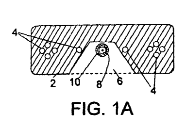
Fig. 1A and 1B: Cross-sections of two sensor cable embodiments
Fig. 2: Tube liner with sensor cable in transport situation,
Fig. 3: Cross-section of a sensor cable on a relining tube, and
Fig. 4: Installation situation concerning the manufacturing; shows a sensor
cable on a relining
tube with protective film impermeable for UV light.
The Figures show the details of the optical sensor cable 1 which is designed
as a flat
ribbon cable. It comprises a profile body 2 with a flat cross-section; the
profile body 2 has at least
one high transparency sub-region 6 which extends alongside the axis of the
sensor cable and
serves to receive optical waveguide 8, 8A. The high transparency sub-region 6
forms an optical
window at the side of the flat side of the profile body.
The first optical waveguide 8 conducts UV light and is coated with an
optically
transparent coating. A second optical waveguide 8A is a standard fibre which
is suitable for
fibre-optical temperature measuring with spatial resolution (generally with a
fibre core doped
with germanium). Preferably, as shown in Fig. 1B, the second optical waveguide
8A is located
asymmetrically outside of the area where the first optical waveguide is
located.
Multiple elongated stiffening or sheathing elements 4 are placed inside of the
profile
body 2. Stiffening elements can also be installed in the transverse direction
of the profile body
(not illustrated in the figures, however).
The cross-section of the profile body 2 is of rectangular shape and has a
greater extension
alongside the support (in width) and a lesser extension perpendicular (in
thickness) to that. The
9
CA 02793387 2012-09-17
profile body can have usual dimensions of approx. 5mm to 15mm in width and
usual dimensions
of 3mm to 6mm in thickness (narrower extension). The first optical waveguide 8
is located in the
neutral layer of the profile body 2 with regard to the bending stress; hence
it is located in the half
thickness of the profile body 2.
Due to this flat ribbon cable design the sensor cable has different flexural
rigidity
properties in both layers which are perpendicular to the cable axis. It
essentially important that
the flexural rigidity of the profile body around the axis, which is parallel
to the transverse
elongation and perpendicular to the longitudinal direction of the profile
body, is high enough to
ensure that the profile body, for the usual stress that exists when placing a
relining tube and even
when the preparation works including the manufacturing process are performed,
does not bend
more than the value necessary to exceed the ultimate strength of the optical
waveguide placed
inside the profile body. Modern optical waveguides have a high ultimate
strength with regard to
bending.
The sensor fibre (the first optical waveguide) is in the sub-region 6 which is
transparent to
UV light and is enclosed by a transparent coating.
Figures 1A and 113 show embodiment examples of profile body with transparent
sub-regions 6, 6' which open like a funnel to one flat side of the profile
body each. Moreover,
Figure 1B shows a possible arrangement with optical waveguide 8 based on
quartz and a
temperature sensor fibre 8A.
The loose arrangement of the sensor fibre 8 based on quartz within a
transparent tube
which scatters UV light (coating 10) allows for another advantage: more UV
light can be coupled
in the fibre core.
Fig. 2 shows a relining tube 20 with a sensor cable 1, 2 in a state where the
relining tube
20 is transported to the installation site in a transport box 40. This Figure
illustrates the problem
of bending and pressure stress on the relining tube during the manufacturing
process (packaging)
at the factory and during transport. The consolidated relining tube is being
deposited in transport
boxes 40 (meander-like) directly from the manufacturing belt. When embedding
the sensor cable
(e.g. in 12 AM position, this corresponds to the vertex area in the old pipe
of the channel to be
repaired) on the relining tube and subsequently depositing it in the transport
box, the outer tube
sections have to bear strong bending stress in the reverse points 42 (180
turn) and also have
high pressure stress due to the high weight of the relining tube (up to a few
tons of weight).
When bending the sensor cable 2, the flexural rigidity of the optical
waveguide(s) 8 placed inside
the profile body will not be exceeded, even though both outer coatings of the
sensor cable will
CA 02793387 2012-09-17
come into contact due to the 180 turn. A prerequisite for the mechanical
protection of the
optical waveguide is the embedding of the optical waveguide in the sensor
cable, i.e. in the
neutral layer of the profile body with regard to the bending stress. Embedded
in the neutral layer
of the profile body, the optical waveguide will only have to bear little to no
traction and
elongation stress when bent. Bends will only occur in brief periods, i.e. in
the time from
packaging into a transport to the withdrawal from the transport box shortly
before the
installation.
Fig. 3 shows a cross-section of a sensor cable which is placed flat on the
surface of a
relining tube 20. The tube layer 20' consists of glass-fibre reinforced, light
curable plastic (resin)
with a thickness depending on the relining tube diameter each. The thickness
may be up to
10mm. The glass-fibre reinforced synthetic resin layer is fitted with a cover
film 22 on both sides.
When fastening the sensor cable on the relining tube, the sensor cable is
fitted between the
relining tube (directly on its surface) and the UV protective film 24. This is
why the protective film
24 impermeable to UV light is placed above the fitted sensor cable 1, 2. In an
installation
situation for the purpose of repairing a defective sewer, a relining tube is
installed together with
the sensor cable. For this installation, one would preferably proceed to place
the sensor cable in
the highest position possible, i.e. 12 AM, in the old pipe.
Figure 4 shows a drawing of the installation situation during the
manufacturing of a
relining tube 20 with a sensor cable 1, 2 fitted onto the surface of a
relining tube 20 and below a
UV protective film 24. This is the situation before inserting the fibre tube
into a defective sewage
pipe and before inflating the tube by means of pressurised air in order to
make the tube fit
perfectly tight to the inner surface of the pipe.
Reference numerals
1 Sensor cable
2 Cable sheathing, profile body
4 Sheathing elements
6, 6' Transparent sub-regions
8 First optical waveguide (conducts UV light)
8A Second optical waveguide
Transparent coating, tube
Relining tube
20' GRP body (tube location)
11
CA 02793387 2012-09-17
22 Cover film(s) for the relining tube
24 UV protective film
40 Transport box
42 Bending areas
R' Bending radius relining tube
12