Note: Descriptions are shown in the official language in which they were submitted.
CA 02793684 2012-09-18
WO 2010/113046 PCT/1B2010/050445
1
Description
Title of Invention: DEVICE ESPECIALLY FOR VENTILATION
OF NITRIC OXIDE IN THE PARANASAL SINUSES AND THE
SUPPRESSION OF DISEASES OF THE UPPER RESPIRATORY
TRACT
Technical Field
[1] The invention relates to a device for ventilation of nitric oxide in
the paranasal
sinuses and the suppression of diseases of the upper respiratory tract,
especially to
wash over the paranasal sinuses to suppress respiratory disorders, said device
comprising a housing; a vibration generator arranged in the housing; an energy
supply
unit connected to the vibration generator; a vibration transfer unit in
mechanic/physical
contact with the vibration generator, partly configured in the house. The
proposed
device is preferably suitable for the treatment and examination of diseases of
the lower
and upper respiratory tracts and of the pulmonary circulation, respectively,
such as, for
example, rhinitises, rhinosinusitises of various origins, nasal congestion,
common cold,
flu, bronchitis, bronchus contraction and chronic obstructive pulmonary
disease
(COPD).
Background Art
[2] A skull of a living being, e.g. a human skull contains several air-
filled spaces, so-
called paranasal sinuses, communicating with the nasal cavity. The biggest of
the
paranasal sinuses is the so-called maxillary sinus or facial cavity, the
volume of which
is, in adult humans, 4 cm3 to 35 cm3, on average 12 cm'. Paranasal sinuses are
joined to
the nasal cavity via small orifices of a diameter of 1 to 3 mm. Since the
mucous
membrane which lines the sinuses is united with the mucous membrane of the
nasal
cavity, the diseases of the nasal cavity and of the sinuses usually occur in
correlation,
as rhinosinusitis.
131 Rhinosinusitis has several forms. The most frequent one is common cold,
meaning
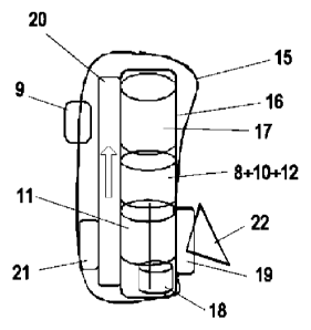
inflammation due to a weak infection of the upper respiratory tract.
Rhinosinusitis of
allergic origin, due to alien substances, mainly vegetable pollens, causing in-
flammation is also frequent.
[4] The so-called 'rhinitis medicamentosa' develops due to the continuous
use in excess
of 7-10 days of locally applicable nasal vein-contracting preparations.
151 The hygienic state of the respiratory tracts, a function mainly of
mucociliar transport,
is of decisive importance for the development of respiratory diseases.
Mucociliar
transport is produced by the one-way whip-like motion of the cilia of the
mucous
membrane. Transport is influenced by the movement of the cilia and the
viscoelastic
CA 02793684 2012-09-18
WO 2010/113046 PCT/1B2010/050445
2
properties of the mucous material.
[6] The ventilation of the sinuses is equally essential in regard of the
development of res-
piratory diseases: blocked or poorly ventilated sinuses will be subject to
inflammation.
[7] A well-known method for the examination of the ventilation of the
sinuses concerns
the observation of the quantity of nitric oxide gas (NO) exhaled through the
nose. NO
is a substance produced by the human body, which has a protective effect.
[8] The treatment of rhinitis and of diseases of the upper respiratory
tract is usually quite
simple. The patient needs rest and liquid replacement, and medicines, e.g.
pain killers
and fever reducers and, furthermore, antihistamines, vitamins, mucus-
dissolvents and
expectorants may be provided to alleviate the symptoms. As for the treatment
of
rhinitis provoked by pathogens, there is effectively no adequate medication
for viruses.
Antibiotics are used to prevent and treat bacterial infections. If the
rhinitis fails to
improve under the effect of medication, it may spread over to the sinuses.
[9] From among the diseases of the lower respiratory tract, asthma and COPD
treatment
uses medicaments, but the sudden temporary aggravation of asthma and COPD
cannot
be prevented effectively with medicinal treatment, because such events are
usually due
to substances that enter the human body suddenly, with air. Therefore, it is
justified to
use also a treatment which can enhance the self-clearing mechanism of the
lower res-
piratory system quickly, if need be.
[10] US 2003/0172939 discloses a method and the device whereby it can be
realised to
eliminate congestion in the internal facial cavities with the help of
vibration. The
device proposed to that effect comprises a handle part containing a power
source and a
vibration generator, connected to an external vibration transmitter, and it is
this
external vibration transmitter that must be pressed against the selected body
surface, so
as to transmit vibration through the body surface to the hard tissues. It is a
particular
feature of the method, and the device is designed accordingly, that it is to
eliminate
congestions mechanically, via the transmitted mechanical vibrations, mainly to
reduce
or eliminate ear pain, and the vibration transmitter is designed so that the
user can grip
it between an opposing pair of teeth, in which case the device can relieve
tooth-ache
according to the document. The device achieves its purposes by applying
subsonic
frequency, i.e., a frequency below the audibility range of the human ear. The
document
makes no mention of the possibility to liberate NO via the vibrations and
hence it does
not contain any specific solution or proposal to that effect either.
[11] US 2008/0195001 describes a device and a method to alleviate pain in
the sinuses,
where the device is again realised as a device which transmits vibrations to
the human
body. To make the device applicable also in lying position, it has a specially
curved
shape, and the vibration transmitter that transfers the vibrations to the body
surface is
at an angle with the longitudinal axis of the device. This configuration, too,
is meant to
CA 02793684 2016-06-07
= 23 3 0 5-13 0 8
3
mechanically loosen and eliminate debris and congestion, but the document
makes no
mention of the vibration frequency being used. The main drawback of this con-
figuration, the same as of the device mentioned before, is that it tries to
eliminate or
terminate the deposits and the bad general feeling by producing a mechanical
effect.
[12] It is well-known that NO concentration in the sinuses is exceptionally
high in healthy
humans: it may attain 20-30 ppm (parts per million molecules). Therefore,
there is a
possibility that high NO concentration in the sinuses may also have some
protective
function. Efforts to raise NO concentration in the nose exploit this
possibility. Since
the NO outflow from the sinuses in the direction of the nose is hindered,
various
technical solutions have been devised to raise the nasal NO concentration.
[13] Lundberg J. and Weitzberg E. realised (cf. patent application WO
03/063703) that
oscillating airflow significantly increases the quantity of NO in the nose,
because gas
exchange between the sinus and the nasal cavity intensifies at the resonance
frequency
of the sinuses. According to WO 03/063703, it is possible to increase the
quantity of
NO in the main nasal cavity with the help of an oscillating airflow or by
devices which
generate such airflow. The oscillating airflow can be generated by humming
with
closed mouth, i.e. the nasal phonation of the sounds 'm' and 'n', or by
external sound
source. Such devices can be used in humans for diagnostic purposes.
[14] Strong humming, however, is quite tiring, and the humming of air
exhaled through
the nose or the inhaling through the nose of air vibrated with the help of an
external
device cannot be realised if the swollen nasal mucous membrane already
prevents the
flow of air through the nose. Therefore, in most patients, the ventilation of
the sinus by
the application of an oscillating airflow cannot be applied clinically.
[15] WO 03/013653 discloses another possibility for the treatment of
rhinitis. This is the
application of light pointed into the nose, in other words: rhinophototherapy.
Similar
solutions are described also in e.g. US 2006/0271024. Rhinophototherapy, too,
has the
disadvantage that it cannot be used with a stuffy nose.
Disclosure of Invention
[16] One of the main problems with the treatment of rhinitis or
rhinosinusitis is the low
co-operation propensity of patients who consider the disease unpleasant, but
not
dangerous. They stop treatment when the symptoms alleviate and, upon the
return of
the symptoms, the same treatment is, of course, less efficient or it has no
effect at all.
Therefore, there is a significant need for such simple and efficient treatment
methods
as can be applied by the patient in parallel with the routine everyday
activities.
[17] The vibration parameters of the maxillary and frontal sinuses,
respectively, can be
described by a known mathematical formula, the Helmholtz equation, where
resonance
CA 02793684 2012-09-18
WO 2010/113046 PCT/1B2010/050445
4
frequency is the function of the volume of the cavity, the diameter measured
at the
neck of the cavity and the length of the neck at constant vibration spread
velocity.
[18] During our measurements with the methods described in the above-
mentioned patent
application WO 03/063703, we unexpectedly found that a higher NO level in the
nose
has a therapeutic effect on diseases of the upper and the lower respiratory
tracts. At the
same time, the application of oscillating airflow is not advantageous to treat
such
diseases, since in case of significant or complete nasal congestion the
methods
concerned are non-applicable and, furthermore, there are significant
differences in
therapeutic response by individual. Therefore, in order to treat the patients,
one needs a
method or device suitable to increase the quantity of NO and to trigger
therapeutic
effects in the upper and lower respiratory tracts, respectively, also in case
of nasal
stuffiness.
[19] As disclosed in US 2008/0200848, vibrations applied on the face near
the paranasal
sinuses have a therapeutic effect. However, the vibration generator described
in US
2008/0200848 causes a toot-ache in a significant part of humans, since
vibrations
generated near the maxillary sinus spread over to the roots of the molars of
the upper
teeth . Although it is possible to reduce the performance of the vibration
generator
applied on or near the maxillary bone, then the quantity of NO flushed from
the
maxillary sinus to the main nasal cavity and hence the therapeutic effect
exercised on
the nasal cavity will decrease as well. Therefore, such a vibration generator
device is
wanted as will transmit vibration energy exclusively to the upper apex of the
maxillary
sinus, and the said vibrations do not spread over to the lower wall of the
maxillary
sinus and/or to the tooth roots lying close to it. Given the complexity of the
human
skull, the creation of a vibration generator device of this type requires
careful ex-
perimental analysis, since the actual behaviour of the mechanical vibrations
on spatial
surfaces of a sophisticated shape and with sutures has parameters that cannot
be
modelled in advance.
[20] Our experiments surprisingly showed that vibrations transmitted
perpendicular to the
longitudinal cross-section of the nose, above the zygomatic bone from among
the skull
bones, can enhance the quantity of NO in the nose without causing a tooth-
ache.
Vibration generated on the zygomatic bone partly is partly reflected through
the three
extensions of the zygomatic bone and at the juncture of the zygomatic and the
maxillary bones, and it partly penetrates to the maxillary and frontal bones
and the
mastoid portion of the temporal bone but there it already reverberates with
multiple
direction changes, dispersed and significantly weakened. The vibration waves
divided
in three directions are re-united again in the area of the so-called
osteomeatal complex
on the lateral side of the common nasal cavity. The upper apex of the
maxillary sinus is
located in the zygomatic bone. Although more than 90 percent of the volume of
the
CA 02793684 2016-06-07
23 3 05-1 3 08
maxillary sinus is in the maxillary bone, surprisingly, the vibrations in the
zygomatic
bone which attain the upper apex of the maxillary sinus are capable also in
themselves
to wash over to the nasal cavity the total amount of NO stored in the ma
xillary sinus.
[21] However, no NO increase was experienced in the nose upon touching to
the
zygomatic bone that part of the device described in US 2008/0200848 which is
brought
into contact with the human face. Presumably, the frequency of the vibrations
generated by the device does not comply with the resonance frequency of the
maxillary
sinus and hence there is no enhanced gas exchange between the maxillary sinus
and the
nasal cavity.
[22] It is commonly known that the volume and resonance frequency of the
maxillary
sinus is, firstly, highly different by individual and, furthermore, it changes
con-
tinuously with time in each individual. Change with time in a given individual
is due to
the so-called nasal cycle. During the nasal cycle, the internal cross-section
of the nose
changes periodically due mainly to the change in the swelling of the mucous
membrane. The changes in the thickness of the mucous membrane affect both the
cross-section and the length of the ostium of the sinuses. The resonance
parameters
change continuously under the effect of the resultant of the narrowing of the
opening
and the simultaneous increase of the length of the ostium due to the swelling
of the =
mucous membrane, and hence they are diffieult to calculate. Therefore, we need
a
vibration generator device the frequency of which can be altered continuously
within a
pre-set range by manual control over the period of a single treatment cycle,
so that the
applied vibrations match the actual resonance frequency of the sinuses several
times.
The mechanical construct according to patent application US 2008/0200848,
however,
contains several inert masses forced onto a mechanical trajectory that cause
strong
noise in case of fast frequency change, and the power impulses result in the
fast
erosion of the suspension points of the moving masses.
[23] Since the Helmholtz resonance frequency of the paranasal sinuses may
differ in
humans, and since the Helmholtz resonance frequency of the paranasal sinus of
a given
individual changes continuously with the nasal cycle, it is necessary to
develop a
vibration generator device for therapeutic purposes which will scan the
possible
resonance frequencies typical of paranasal sinuses in humans and is suitable
for in-
creasing the quantity of NO in the nasal cavity and for the treatment of
respiratory
diseases in humans, so that the vibrations generated by the device shall not
spread on
the upper teeth and cause tooth-ache.
[24] We have realised that it is necessary to have a mechanical vibration
generator which
is capable of fast revolution changes in the desired frequency range, and the
parts of
which are not exposed to significant attrition.
81549457
6
[25] Vibration generator devices known in the art usually comprise a power
source, a
switch and other sub-units to promote their use, which represent attached
vibrating components.
The vibration of multi-component systems, however, generates more noise. High-
frequency noise
can reach the roots of the upper teeth, whereas low-frequency noise can cause
eyeball impairment.
Therefore, such device is needed as will not transfer any potentially harmful
noise to the human
body.
[26] It is possible to use for example internal and external vibration
damping
configurations to reduce the noise. Internal noise damping can be realised
through the integration
of vibration damping materials or through the tight mechanical fitting of the
various vibrating
parts. The use of internal vibration damping materials is limited by the
growth of the size of the
device. The tight integration of the inner sub-units of the device, on the
other hand, aggravates the
replacement of the power sources.
[27] It was found to our surprise that only those versions of the vibration
generator
devices produced in various technical forms are suitable for the treatment of
diseases of the upper
and lower respiratory tracts, respectively, when brought into engagement with
the human face as
do not transfer to the facial bone vibration in excess of 1500 Hz and,
moreover, in intermittent
mode of operation, the vibration frequency of which changes from the bottom to
the ceiling limit
at least ten times in 30 seconds.
[28] According to an aspect of the present invention, there is provided a
device for
the ventilation of nitric oxide in the paranasal sinuses, the device
comprising a housing, a
vibration generator arranged in the housing, an energy supply unit
communicating with the
vibration generator, a vibration transmitter partly arranged in the housing
and in
mechanical/physical contact with the vibration generator, wherein the
vibration transmitter is
formed as a unit preventing transmission of vibrations below a lower threshold
value of 50 Hz
to a human body, a treatment part of the vibration transmitter which comes
into contact with
the human body is formed as a treatment component vibrating with a maximum
threshold
value of 1500 Hz, and the vibration generator is formed as a unit producing at
least 10
vibration periods that increase from the lower threshold value to the maximum
threshold value
and decrease from the latter to the former over 30 s.
CA 2793684 2017-06-27
CA 02793684 2016-06-07
23305-1308
7
[28a] According to another aspect of the present invention, there is
provided use of
the device as described above for ventilation of nitric oxide in a paranasal
sinus.
[28b] According to another aspect of the present invention, there is
provided use of
the device as described above, for suppression of disorders in an upper
respiratory tract.
[29] Some further advantageous embodiments of the invention are described
below.
Description of Drawings
[30] In what follows, non-limiting examples of embodiments of the
invention will
be described in more detail with reference to the attached drawings which
include an
exemplary embodiment of the proposed device, and in which: -
[31] Figure 1 is a detail of the human face where the facial parts affected
by an
embodiment of the invention are sketched;
[32] Figures 2a, 2b highlight the surroundings of the maxillary sinus upon
which the
proposed device exerts its effect;
[33] Figure 3 is a possible block diagram of the vibration generator;
[34] Figure 4 is a sketch of a possible embodiment of the device according
to the
invention;
[35] Figure 5 shows a possible course of the vibration frequency produced
by the
vibration generator;
[36] Figures 6a, 6b show other possible courses of the vibration frequency
produced
by the vibration generator;
[37] Figures 7 and 8 show the effect of treatment with the device according
to an
embodiment of the invention at different vibrations;
CA 02793684 2016-06-07
23305-1308
8
[38] Figures 9 and 10 show representative acoustic rhynometric study
results in
adult males and females, respectively;
[39] Figure 11 shows the changes in the resonance frequency of the
maxillary sinus
due to the nasal cycle in males and females;
[40] Figure 12 shows the vibration frequency of a possible embodiment of
the
device according to the invention;
[41] Figures 13A and 13B show the vibration spectrum of a possible
embodiment of
the device according to the invention when the maximum nitric oxide signal
typical of men
and women, respectively, is triggered, and
[42] Figure 14 sketches a possible method of the operation of the device
according
to an embodiment of the invention on a block diagram.
Best Mode
[43] Figure 1 shows the general overview of a part of the human face, in
which
areas affected by the invention are indicated. The figure shows frontal sinus
1, maxillary sinus
2 and the line of tear duct 3. Vibrations spreading downward in the maxillary
bone, in the line
of tear duct 3, reach the upper teeth and cause tooth-ache.
[44] Figure 2a provides a closer view of zygomatic bone 4, where arrow 5
indicates
the direction of the applied vibrations. Figure 2b shows maxillary sinus 2,
osteomeatal
complex 6 (location of the ostium of the nasal cavity), and the position of
the upper teeth 7.
The direction in which the vibration is to be transmitted to zygomatic bone 4
is again marked
by arrow 5.
[45] Figure 3 shows a possible embodiment of the device according to the
invention
at block diagram level. Note that, on the basis of its function, the concrete
structure of each
unit will be obvious to a person skilled in the art. The vibration generator
known from earlier
solutions is associated according to the invention with a novel-type control
unit. In the
CA 02793684 2016-06-07
23305-1308
8a
example shown here, a function generator producing the applied wave form is a
saw-tooth
generator - by the way, it may be something else -, made of microprocessor 8,
which can be,
for example, of the type Atmel AT tiny 261 operating in the customary
connection. The saw-
tooth generator is activated by a switch 9, which is realised in the given
case as a push-button
configured on the housing of the device according to the invention, not
indicated separately in
the drawing, in a way that provides for easy manual operation. Microprocessor
8 produces
pre-set voltage values and through that frequency values, conducted through
vibration sensor
to motor 11. Motor 11, which essentially constitutes the main part of the
vibration
generator is, in the given example, a high-revolution vibration motor, such as
Penny motor
10 Series 1202 or Faulhaber motor Series 0206, but any motor 11 customary
in such devices can
be used with appropriate parameter settings.
[46] Furthermore, the saw-tooth generator of microprocessor 8 is
connected to a
switching and timing stage 12, partly to link power source 13 of the device to
the saw-tooth
generator, and partly, optionally, to provide for the 30 second treatment
cycle which is ideal
and necessary according to our measurements. Vibration sensor 10 monitors with
the help of
one or several electrical transducers the frequency and amplitude of the
vibration produced,
and provides feedback which influences the production of the envisaged
vibration, with a
defined nominal frequency and amplitude, by the saw-tooth generator. Stage 12
is connected
to spatial position switch 20, the role of which will be described in the
document later on.
[47] A preferred embodiment of the device according to the invention
contains a
microprocessor 8 that can be re-programmed from an external computer in
several modes of
operation, and the optimum frequency scanning modes of operation can be
activated from the
memory. Consequently, the device can be used efficiently with several kinds of
patient
groups. To ensure optimum effect, a preferred embodiment according to the
invention makes
it possible to build in a revolution or vibration sensor into the part of the
device which gets
into contact with the human body, which will then in the known way provide
feedback to
microprocessor 8 and keep the operation parameters within the desired values.
CA 02793684 2016-06-07
= 23305-1308
8b
[48] Figure 4 shows a sketch of a possible physical realisation of the
device
according to an embodiment of the invention which, however, may be altered in
line with the
area of utilisation, needs and possibilities ever. To provide for hand-
holdability, a rod-shaped
housing 16 located in the designed mantle 15 contains, one after the other,
power source 17,
which may be a battery, an accumulator or some other source of electric
current, if an electric
vibration generator is used. A vibration controller contains switching and
timer stage 12,
microprocessor 8 with saw-tooth generator and vibration sensor 10. That is
followed by the
vibration generator, which contains electric motor 11 and eccentric wheel 11
made of the
same piece as its axe or wedged onto it, which transmits the vibrations
through hammer 19,
essentially the vibration transmitter, protruding from the side of housing 16
of the device and
indicated symbolically. Spatial position switch 20 guarantees the operation of
the device
exclusively if held in the right position, and the right position is indicated
by sound emitter 21.
The total device can be designed as a unit of 50-100 mm length and 15-35 mm
width (or
diameter, if a cylindrical housing is used), which can be fixed even on a key-
ring, ready for
application at any time.
[49] According to an embodiment of the invention, in order to avoid tooth-
ache, the
vibration transmitter of the device according to an embodiment of the
invention in contact
with the human body is partly provided with vibration damping material
(vibration damper
component 22) and, on the other hand, due to its design, the device can be
held by a natural
grip so that vibration
CA 02793684 2016-06-07
23 305-1 308
9
generated by the device shall not spread downwards, towards the teeth, but be
divided
along the three extensions of 4 zygomatic bone 4, and reach the upper teeth
only in a
significantly weakened form.
[50] As for its technical construction, the device includes a maximum of
one vibration
generator which consists of no more than two independent mechanical sub-parts
(piezo-ceramic, or axe and eccentric wheel 18, or mechanical component moved
by
electromagnet); furthermore, the device contains at least one flexible or
elastic internal
vibration damping element (e.g. spring to press down power source 17), and at
least
one elastic external vibration damping component 22 which gets in contact with
the
human face, is skin-friendly and easy to clean. Well-known skin-friendly
vibration
damping materials include polyurethane foam rubbers free of PVC, but these are
difficult to clean, since it takes a long time for the humidity entering the
inside of the
foam to dry. There are also skin-friendly silicon rubber vibration damping
materials
with a water-tight surface, but these dampen the low sounds to a smaller
extent
[51] The simplest mechanical vibration generator device is an errentric
wheel fitted on a
rotating axe, where the rotation of the axe is provided for by a magnetic
power field or
some mechanical force bearing on the axe. The revolving fv-rimtric wheel
results in the
vibration of the axe of motor 11, which is transferred to the fixing points of
the axe, to
housing 16 of electric motor 11, then to casing 15 of electric motor 11, on
which a
hammer part 19 is designed that transmits the vibrations to the human body.
Hammer
part19 is perpendicular to the axe of electric motor 11, and the surface area
of hammer
part 19. in contact with the human body, that is, vibration damping component
22, is
parallel with the axe of motor 11 or it is at an angle of maximum 45 with it.
The
vibration waves divided into three directions in zygomatic bone 4 re-unite on
the
lateral wall of the common nasal cavity, in the area of the so-called
osteomeatal
complex 6, and hence the vibrations produced by the device mainly reach the
upper
apex of maxillary sinus 2. Vibrations penetrating the maxillary bone will only
reach
the upper teeth after a distance that is hundreds of times bigger, with
significant
dispersion and in a weakened form, and therefore, they do not rause tooth-
ache.
[52] Figure 5 shows an exemplary frequency course produced by the saw-tooth
generator
of microprocessor 8. In the case shown here, the saw-tooth generator produces
in-
termittent linear frequency strokes, which appropriately scan the frequency
range from
50 Hz to 1500 Hz several times, so that one vibration cycle takes around 1
second. As
mentioned already, the duration of the total treatment session does not exceed
30
seconds; this is ensured by switching and timing stage 12.
[53] Figures 6a and 6b show diagrams similar to that in Figure 5, but here
the duration of
the vibration cycle is much shorter than 1 second. The frequency stroke
depicted in
Figure 6a is produced by the current of alternating polarity shown in Figure
6b which,
CA 02793684 2016-06-07
233 05-13 08
in practice, means vibrations realised in opposite rotation directions, so
that the am-
plitudes of the vibrations in opposing directions are equal. The change in
polarity
checks electric motor 11 producing the vibrations and hence the individual
frequency
strokes get shorter in time and the total treatment session does not exceed 30
sec9nds
[541 Figures 7 and 8 show effects of treatment with the device according
to the embodiment
at different vibrations. Figure 7 indicates the level of nasal NO release at
various
vibration parameters. The highest NO level is produced if the device is
applied in
scanning mode. As can be observed in Figure 8, NO washed out from the sinuses
enhances mucociliar transport in the nose, as indicated by the decreasing
mucociliar
transport time (saccharin test). The biggest change occurs if the device is
used in
scanning mode.
[55] Furthermore, as shown in Figures 7 and 8, the extent of effects
triggered in males and
females, respectively, is different. This is explained by the fact that the
nasal cycle in-
fluences the resonance frequency of the paranasal sinuses to different extents
in males
and females.
[56] Figures 9 and 10 show experimental measurement results which
demonstrate the
continuous and sex-specific change of the inner parameters of the nose during
the nasal
cycle , which can be examined for example also by acoustic rhynometry. Within
the
nasal cycle, upon the decrease of the swelling of the mucous membrane of the
nose
(decongestion), the mouth section (ostium) of the paranasal sinuses at the
nasal cavity
expands and hence the resonance frequency of the sinuses increases. Figure 9
shows a
representative acoustic rhynometry figure for an adult male where the volume
increased to 6 cm3. Figure 10 depicts an identical measurement for an adult
female,
where the change was bigger than usual, and the device could not detect it any
more.
The records were made at intervals of 1 minute. Point P indicated with an
arrow is the
ostium of maxillary sinus 2 on the left and the right side, respectively. When
the
ostium expands during the nasal cycle, the measurement curves above the arrow
show
a bigger cross-section of the nose, because the ultrasound is refracted also
from the
sinuses (J. Appl. Physiol. 99:616-623 2005).
[57] Another reason why the changes in resonance frequency due to the nasal
cycle differ
in men and women is that the average sinus volume value is also different: in
women,
the sinus volume is smaller and, therefore, with open sinuses, the resonance
frequency
is higher. In case of closed or partly closed sinuses, the difference between
men and
women is not significant. This can be seen in Figure 11 which shows the
changes due
to the nasal cycle in the resonance frequency of maxillary sinus 2 in men
(first row)
and women (backward row). In men, the resonance frequency changes in the range
of
9-164 Hz. Under the effect of treatment with the device according to
embodiments of
the invention, the sinus opens and the resonance frequency of the open sinuses
is in the
range of 132-164
CA 02793684 2016-06-07
23305-1308
11
Hz, on average 144 Hz (n=5). In women, the resonance frequency alternates in
the
' range of 9-348 Hz; under the effect of treatment with the device
according to an embodiment
of the invention the sinus opens and the resonance frequency of the open
sinuses is in the
range of 111-348 Hz, on average 227 Hz (n=5).
[58] Ventilation of sinuses filled with nitric oxide (NO) and at the same
time the quantity
of NO measured in the nose will be at its maximum when the vibration devices
operate
at the actual typical resonance frequency of the paranasal sinus. Therefore,
the device
to be used to ventilate maxillary sinus 2 and to treat various diseases
through the
elevation of the nasal NO level should be capable of operation in special
frequency
scanning modes for men, women, children or other sub-groups (Asian, Afro or
Caucasian), respectively. Figure 12 shows the vibration frequency of a
possible em-
bodiment of the device according to the invention on a representative sample.
The first
vibration, 12A, will open and ventilate the msxillary sinus 2 of men of the
Caucasian
race, whereas the second vibration, 12B, will open and ventilate the maxillary
sinus 2
of women of the Caucasian race. In addition to the vibration modalities 12A
and 12B
shown by way of example only, other vibration patterns can also be produced,
for
example for children. During the treatment session, the vibration modalities
presented
here can, be repeated and combined at an order chosen at one's discretion,
which
ensures the efficient use of the device in individuals of different sex, age
qtc. As will
be obvious to persons skilled in the art, the device can also be designed as a
device
capable of the emission of a single type of vibration only, to be used as
therapeutic
device with a targeted group.
[59] Although the theoretical resonance frequency of open sinuses can be
calculated by a
mathematical formula, in reality, the measurability of the anatomical
parameters is so
inaccurate that the calculated and the effective resonance frequencies differ
sig-
nificantly and, what is more, they are subject to continuous change due to the
nasal
cycle. From a therapeutic point of view, the effective resonance frequency or
resonance frequency band should be the one that results in maximum NO wash-out
from the sinuses.
[60] Figures 13A and 13B show the vibration spectrum of a possible
embodiment of the
device according to an embodiment of the invention when it triggers the
maximum nitric oxide
signal typical of men and women, respectively. The measured resonance
frequency is lower
for men than the one calculated on the basis of the formula, whereas in women
the
resonance frequency defined by measurement is higher than the corresponding
calculated value. Nasal NO measurements with 5 ppb definition indicate that,
instead
of the 144 Hz average resonance frequency calculated for men between the
minimum
' 130 Hz and maximum 164 Hz, in reality, the optimum is 120 Hz
vibration, whereas in
women, instead of the 227 Hz average resonance frequency calculated between
the
. CA 02793684 2016-06-07
' 23305-1308
12
minimum 111 Hz and maximum 348 Hz, in reality, vibration by 380 Hz provides
for
maximum NO concentration enhancement in the nose in case of open sinuses. A
similar gap is
found in regard of the decrease of mucociliar transport time. The reason for
these gaps may be
that the calculated resonance frequency can, as a matter of fact, be provided
only for
individual sinuses, e.g. the maxillary sinus that is the biggest in volume
terms, whereas in
reality, the vibrations spread over to every paranasal sinus and, through the
change in NO
concentration, we define the real resultant resonance frequency that applies
to every paranasal
cavity with NO content.
[61] The specification of the protocol of the device according to
embodiments of
the invention should also take into consideration that, under the effect of
the vibrations, the
closed or partly closed large maxillary sinuses 2 with low resonance frequency
(9-46 Hz) may
open, as a result of which the resultant resonance frequency will increase
suddenly and
significantly (111-348 Hz), especially in women. Therefore, according to
embodiments of the
invention, treatments must always be carried out in a certain frequency range,
in scanning
mode. The application of low-frequency (0-111 Hz) vibrations is preferable
only until the
closed sinuses open up under the effect of treatment. After that, the
vibrations must be applied
for a longer time at the higher resonance frequency of the open sinuses to
provoke maximum
nasal NO concentration enhancement. To raise the efficiency, the vibration
frequency shall
preferably be raised for a short time above the expected resonance frequency,
to ensure also
the ventilation of paranasal sinuses of a lower- than-average volume. At the
same time, the
noise concurrent with the high vibration frequency must be dampened to prevent
any negative
effects.
[62] The mode of operation of the device according to embodiments of the
invention outlined
above - as a possible example - is described in Figure 14 also as a flow
chart, which highlights
two more essential features of the device in addition to its so-far
unprecedented application in
scanning mode, which authorise its use exclusively under physiologically
appropriate
positions and parameters: control of the vertical position and of the period
of use/cycles.
CA 02793684 2016-06-07
= 23305-1308
12a
[63] A vibration-free interval (0.1-3.0 ms, cf. Figure 12) must be inserted
after each vibration
cycle, partly to ensure the partial re-fill of the sinuses with NO and, on the
other hand, since
the low frequency range of the re-started vibration cycle promotes the opening
of the partially
closed sinuses that have not opened fully yet during the previous vibration
cycle. The total
treatment session, of 20-30 s, is made up of vibration cycles reiterated
several times.
[641 Breaks of 4-5 minutes have to be held between the treatment sessions, to
let the paranasal
sinuses get fully refilled with NO gas. Therefore, in a preferred embodiment
of the proposed
device, the device operates for a definite time only after switch-on, then it
automatically stops
and cannot be started again in the next 4 minutes, because
CA 02793684 2016-06-07
23305-1308
=
13
=
switching and timer stage 12 blocks that (cf. Figure 3).
[65] The examples listed above demonstrate that a device operating
according to the
calculated resonance frequency of individual paranasal sinuses is not adequate
for the
ventilation of the biologically effective NO gas from the paranasal sinuses,
because the
calculatfyl resonance frequency and the resonance frequency measured with the
change
in nasal NO concentration are not identical, due to several factors. That is,
the ap-
propriate vibration frequency of devices used for therapeutic purposes and
suitable to
enhance the nasal NO concentration cannot be defined in advance with adequate
accuracy and, furthermore, it is quite certain that the application of a
constant vibration
frequency will not be appropriate for every indivicluil. The chronological
courses of
the optimum vibration modes may be of several kinds, of which the preferred
protocol
for a given group of people can only be determined experimentally.
[66] The device is brought into contact with the clieftkbone in the area of
zygomatic bone
4 in such way that its energy source containing part is on top, as indicated
for example
by a protruding arrow on the external casing a the device. In one preferred
technical
embodiment, the device contains an internal spatial position switch 20 that
will only let
the device be put in operation in the correct, close-to-vertical position. In
this close-
to-vertical position, vibrations transmitted to the skull bone will mainly
spread towards
the osteometal complex 6 part of maxillary sinus 2. If an effort is made to
direct the vi-
brations downward, the device held correctly (arrow upward) will either
[67] i) lay against the temporal or frontal bone due to its size, and
cannot be turned
towards the eye socket (inward and upward), or
[68] the internal spatial position switch 20 will block the operation of
the device.
[69] Consequently, the direction of the vibration transmitted by the device
to the skull
bone cannot be such as would spread directly in the direction of the roots of
the upper
teeth.
[70] If an individual would use the device on the nasal bone or the
forehead, it would
again be impossible to tilt the correctly held device so that the vibrations
should spread
downwards towards teeth 7, since the device held at the wrong angle cannot be
started.
Therefore, the vibrator device applied according to the guide will cause no
tooth-ache,
because it can only be operated in the correct direction shown in the figure.
[71] Possible mechanical and, if appropriate, electronic structure of the
device according
to embodiments of the invention will be obvious and easy to follow to a person
skilled in the art.
Possible solutions are described one by one and in various combinations in
detail in US
2008/0200848, US 2008/0195001, US 2003/0172939, respectively, the contents of
which are considered as reference in full extent in regard of the practical
realisation of
the device.