Note: Descriptions are shown in the official language in which they were submitted.
CA 02793718 2012-09-18
1
{DESCRIPTION}
{Title of Invention}
UNDERWATER MINER CUTTER HEAD, UNDERWATER MINER, AND UNDERWATER
MINING SYSTEM
{Technical Field}
{00011
The present invention relates to, for example, an
underwater miner cutter head for excavating seabed mineral
deposits and attached to the tip of a boom of a miner (mining
machine) that is a component of an underwater mining system
for mining seabed mineral deposits.
{Background Art}
{00021
For example, an unmanned untethered underwater excavator
disclosed in PTL 1 is a known excavator (miner: mining
machine) for excavating the seafloor.
{Citation List}
{Patent Literature}
{0003}
{PTL 1}
Japanese Unexamined Patent Application, Publication
No. HEI-10-212734
{Summary of Invention}
{Technical Problem)
{00041
However, a cutter head disposed at the tip of a ladder
CA 02793718 2012-09-18
2
(boom) 14 of an unmanned untethered underwater excavator 10
disclosed in PTL 1 is a double drum cutter 11, and excavated
muck rolls downward off of it (onto the seafloor). Thus, the
invention disclosed in PTL 1 requires an underwater mucking
machine 30 that collects the excavated muck that has fallen
onto the seafloor and thus is unsuitable for (incapable of)
mining seabed mineral deposits.
{00051
In the double drum cutter 11, an excavation reaction
force is cancelled out in one direction (horizontal direction)
but remains in the other direction (vertical direction). The
reaction force in the other direction acts upon the excavator
as a force causing the excavator to move; thus, an excavator
including the double drum cutter 11 must have a large crawler
and outrigger that support the reaction force in the other
direction, causing a problem of an increase in size of the
excavator itself.
{00061
The double drum cutter 11 also has a problem in that an
unexcavated region remains between one drum cutter and the
other drum cutter, resulting in unsatisfactory excavation
efficiency.
{00071
The present invention has been conceived in light of the
above-described circumstances, and an object thereof is to
CA 02793718 2012-09-18
3
provide an underwater miner cutter head that can cancel out
the reaction forces in the horizontal and vertical directions
to improve the excavation efficiency.
{Solution to Problem}
{0008}
The present invention employs the following solutions to
solve the above-described problems.
An underwater miner cutter head according to the present
invention is attached to an underwater miner disposed on a
seabed and is configured to excavate the seabed, the cutter
head including cylindrical cutter drums disposed on respective
sides defining a regular polygon in plan view, having bits
disposed on the outer circumferential surfaces thereof, and
configured to rotate around corresponding first rotational
axes by first driving sources; and an intake disposed at a
center part of the regular polygon and configured to receive
muck excavated with the bits, wherein the rotating directions
of the cutter drums are set such that the bits sequentially
move toward the intake.
{0009}
In the underwater miner cutter head according to the
present invention, the muck excavated with the bits is
sequentially transported to the intake and collected; thus, a
device such as an underwater mucking machine that collects the
excavated muck that has fallen to the seafloor is not
CA 02793718 2012-09-18
4
required.
Since the cutter drums are disposed on the sides defining
a regular polygon (e.g., square) in plan view, the reaction
forces in the horizontal and vertical directions are cancelled
out.
{00101
With the underwater miner cutter head, it is more
preferable that the cutter drums be attached via a cutter
support arm, and a plate-like turning base rotated by a second
driving source around a second rotational axis passing through
the center of a regular polygon is provided.
{C)011}
With such an underwater miner cutter head, since the
cutter drums rotate together with the turning base around the
second rotational axis passing through the center of a regular
polygon, unexcavated areas remaining between adjacent cutter
drums are eliminated, improving the excavation efficiency.
100121
It is more preferable that the underwater miner cutter
head include a third driving source configured to slide the
turning base in a direction orthogonal to the second
rotational axis.
{00131
With such an underwater miner cutter head, since the
cutter drums slide together with the turning base in a
CA 02793718 2012-09-18
direction orthogonal to the second rotational axis,
unexcavated areas remaining between opposing cutter drums are
eliminated, further improving the excavation efficiency.
{00141
The underwater miner according to the present invention
includes one of the above-described underwater miner cutter
heads.
{0015}
With such an underwater miner according to the present
invention, since the reaction forces in the horizontal and
vertical directions generated during excavation are cancelled
out, an increase in size of the crawler and outrigger can be
avoided, and thus, an increase in size of the underwater miner
itself can be avoided.
{0016}
The underwater mining system according to the present
invention includes the above-described underwater miner.
{0017}
With the underwater mining system according to the
present invention, a device such as an underwater mucking
machine that collects the excavated muck that has fallen to
the seafloor is not required, achieving a decrease in size of
the underwater miner itself. Thus, the entire underwater
mining system can be simplified, and the manufacturing cost
can be reduced.
. CA 02793718 2012-09-18
6
{Advantageous Effects of Invention}
100181
The underwater miner cutter head according to the present
invention is advantageous in that the reaction forces in the
horizontal and vertical directions can be cancelled out,
improving the excavation efficiency.
{Brief Description of Drawings}
{0019}
{Fig. 1}
Fig. 1 is a perspective bottom view of an underwater
miner cutter head according to an embodiment of the present
,
invention.
{Fig. 2}
Fig. 2 is a sectional side view of the underwater miner
cutter head according to an embodiment of the present
invention.
{Fig. 3}
Fig. 3 is a bottom plan view of the underwater miner
cutter head according to an embodiment of the present
invention.
{Fig. 4}
Fig. 4 is a conceptual configuration diagram illustrating
a specific example of an underwater mining system including,
as a component, an underwater miner having an underwater miner
cutter head according to an embodiment of the present
CA 02793718 2012-09-18
7
invention.
{Description of Embodiments}
{0020}
An underwater miner cutter head according to an
embodiment of the present invention will now be described with
reference to Figs. 1 to 4. Fig. 1 is a perspective bottom
view of the underwater miner cutter head according to this
embodiment. Fig. 2 is a sectional side view of the underwater
miner cutter head according to this embodiment. Fig. 3 is a
bottom plan view of the underwater miner cutter head according
. to this embodiment. Fig. 4 is a conceptual configuration
diagram illustrating a specific example of an underwater
mining system including, as a component, an underwater miner
having an underwater miner cutter head according to this
embodiment.
{0021}
An underwater miner cutter head (hereinafter, simply
referred to as "cutter head") 20 according to this embodiment
is attached to, for example, the tip of a boom 3 of an
underwater miner (underwater mining machine) 2, which is a
component of an underwater mining system 1 for mining a seabed
mineral deposit G, such as that illustrated in Fig. 4, and is
used for excavating the seabed mineral deposit G.
The underwater mining system 1 includes the underwater
miner (hereinafter, simply referred to as "miner") 2, a
CA 02793718 2012-09-18
8
lifting device 4, and a mining mothership 5.
The miner 2 includes a cutter head 20, a boom 3, a moving
device 6 having a crawler, a slurry pump 7, and a flexible
suction pipe 8. The seabed mineral deposit G excavated by the
cutter head 20 is sucked into the slurry pump 7 through the
suction pipe 8 together with seawater and is pneumatically
pumped (delivered) as slurry through a slurry hose 9, which is
described below.
The suction pipe 8 is disposed inside the boom 3 and the
main body of the miner 2; one end thereof is connected to
suction port of the cutter head 20 described below, and the
other end is connected to a suction port of the slurry pump 7.
{0022}
The lifting device 4 includes the flexible slurry hose 9,
an underwater pump unit (subsea pump unit) 10 including a
high-pressure underwater pump (not shown), and a lifting pipe
11. The slurry lifted to the underwater pump unit 10 through
the slurry pump 7 and the slurry hose 9 is pneumatically
pumped (delivered) through the lifting pipe 11 by the high-
pressure underwater pump constituting the underwater pump unit
10.
{0023}
The mining mothership 5 holds a slurry processing system
(not shown); the slurry lifted to the mining mothership 5
through the underwater pump unit 10 and the lifting pipe 11 is
CA 02793718 2012-09-18
9
separated by the slurry processing system into the seabed
mineral deposit G and unwanted matter. Then, the seabed
mineral deposit G is collected and the unwanted matter is
discarded into the ocean.
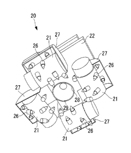
{0024}
As shown in at least one of Figs. 1 to 3, the cutter head
20 includes four cutter drums 21, a turning base 22, a
hydraulic (rotary) swivel 23, hydraulic motors 24 for the
corresponding cutter drums (first driving sources), and
hydraulic motors (second driving sources) 25 for a (first)
turning base.
The cutter drums 21 are cylindrical members that are made
to spin around corresponding (first) rotational axes (center
axes) C by the corresponding hydraulic motors 24 for the
cutter drums. A plurality of (twelve in this embodiment) bits
26 are spirally arranged on the outer circumferential surface
of each cutter drum 21. The cutter drums 21 are disposed such
that the rotational axes C thereof are positioned on sides
defining a square in plan view and are attached to the turning
base 22 via cutter support arms 27. The bits 26 are disposed
on outer circumferential surfaces of the cutter drums 21
facing each other in line symmetry such that the spiral
(alignment) directions of the bits 26 are opposite, i.e., such
that the line-symmetrically arranged bits 26 are presented
sequentially as the cutter drums 21 that face each other in
CA 02793718 2012-09-18
51258-64
line symmetry (disposed on opposing sides) rotate.
100251
A discharge pipe 29 having an intake 28 at one end (lower
end in Fig. 2) passes through the center part of the turning
base 22; and a large (flat) gear 32 engaged with small (flat)
gears 31, which are secured to rotary shafts 30 of the
hydraulic motors 25 for the turning base, is disposed on the
center part.
The large gear 32 is secured to the upper surface of the
turning base 22 such that the turning base 22 and the large
gear 32 rotate (revolve) around the discharge pipe 29.
{0026}
The hydraulic swivel 23 includes a fixed portion 23a and
a rotating portion 23b. The fixed portion 23a is secured to
the discharge pipe 29 with a frame (support member), which is
not shown, and the rotating portion 23b is secured to the
large gear 32 =with a pipe frame 33. The rotating portion 23b
of the hydraulic swivel 23 and the pipe frame 33 can rotate
(revolve) around the discharge pipe 29 together with the
turning base 22 and the large gear 32.
00271
The hydraulic motors 24 for the cutter drums are
hydraulic motors that rotate (spin) the cutter drums 21 around
the rotational axes C by using hydraulic fluid supplied from
the miner 2 through the hydraulic swivel 23. The hydraulic
CA 02793718 2012-09-18
51258-64
11
motors 24 for the cutter drums are accommodated in the
corresponding cutter drums 21. The rotating directions of the
hydraulic motors 24 for the cutter drums are set such that the
seabed mineral deposit G excavated with the bits 26 flows to
the intake 28, i.e., such that the bits 26 disposed on the
outer circumferential surfaces of the cutter drums 21
sequentially move toward the intake 28. In other words, the
rotating directions of the hydraulic motors 24 for the cutter
drums are set such that the line-symmetrically arranged bits
26, as viewed from below, sequentially move from the outer
side to the inner side as the cutter drums 21 disposed on
opposing sides rotate.
(00281
The hydraulic motors 25 for the turning base are
hydraulic motors that rotate (revolve) the turning base 22
around a center axis (longitudinal axis: second rotational
axis) of the discharge pipe 29 with the hydraulic fluid
supplied from the miner 2 through the hydraulic swivel 23.
The hydraulic motors 25 for the turning base are vertically
disposed on the upper surface of the turning base 22 (in this
embodiment, two hydraulic motors 25 are disposed on the upper
surface of the turning base 22 so as to face each other). The
small gears 31 engaged with the above-described large gear 32
are secured to the rotary shafts 30 of the hydraulic motors 25
for the turning base. The small gears 31 rotating in one
CA 02793718 2012-09-18
12
direction (the direction indicated by a thick solid arrow in
Fig. 3) cause the cutter drums 21, the cutter support arms 27,
the turning base 22, the large gear 32, the pipe frame 33, and
the rotating portion 23b of the hydraulic swivel 23 to rotate
in the one direction. The small gears 31 rotating in the
other direction cause the cutter drums 21, the cutter support
arms 27, the turning base 22, the large gear 32, the pipe
frame 33, and the rotating portion 23b of the hydraulic swivel
23 to rotate in the other direction.
The hydraulic motors 25 for the turning base are secured
= to the above-described frame (support member) and do not
rotate (revolve) in the same manner as the discharge pipe 29
and the fixed portion 23a of the hydraulic swivel 23.
{0029}
With the cutter head 20 according to this embodiment,
muck excavated with the bits 26 is sequentially transported to
the intake 28 and is collected. Accordingly, it is possible
to provide an underwater mining system that does not require a
device such as an underwater mucking machine that collects the
excavated muck that has fallen to the seafloor.
Since the cutter drums 21 are disposed on the sides
defining a square in plan view, the reaction forces in the
horizontal and vertical directions are cancelled out.
The cutter drums 21 rotate, together with the turning
base 22, around the center axis of the discharge pipe 29
CA 02793718 2012-09-18
13
(second rotational axis passing through the center of a
regular polygon). Thus, unexcavated areas between adjacent
cutter drums 21 can be eliminated, improving the excavation
efficiency.
{00301
The present invention is not limited to the embodiment
described above, and various modifications may be made without
departing from the scope of the invention.
For example, a hydraulic motor (third driving source) for
a (second) turning base is preferably included to slide the
turning base 22 in a direction orthogonal to the center axis
of the discharge pipe 29.
In such a cutter head, the cutter drums 21 can slide,
together with the turning base 22, in a direction orthogonal
to the center axis of the discharge pipe 29. Thus,
unexcavated areas between opposing cutter drums 21 can be
eliminated, further improving the excavation efficiency.
{0031}
{Reference Signs List}
1 underwater mining system
2 (underwater) miner
20 (underwater miner) cutter head
21 cutter drum
22 turning base
24 hydraulic motor (first driving source) for cutter drum
CA 02793718 2012-09-18
14
25 hydraulic motor (second driving source) for (first)
turning base
26 bit
27 cutter support arm
28 intake
C (first) rotational axis