Note: Descriptions are shown in the official language in which they were submitted.
CA 02793943 20 12-09-2 1
Printed: 02/02/2012 DESCPAMD
GB2011050563
01/09/ 2011 10: 32 01179103201 HASELTIkE LAKE PAGE
08/20
PCT/GB 2011/050 563 - 01-09-201
A SEPARATOR FOR SEPARATING SOLIDS FROM AN INFLUENT
This invention relates to a separator for separating solids from an influent,
and is
particularly, although not exclusively, concerned with a separator for
removing grit from
wastewater flow.
Wastewater such as that arriving at a sewage treatment facility can contain
grit which
causes wear to processing equipment and, if the grit accumulates, loss of
performance.
A separator for the removal of grit from wastewater flow is described In
US6645382,
The separator comprises a tray assembly made up of a plurality of stacked
settling
plates, in the form of trays having a frusto-conical shape. Each tray has a
centrally
located opening and a lip which extends about the periphery of the tray and
projects
Inwardly. The trays are spaced apart axially so that wastewater may flow
between the
trays. The stacked trays are submerged in a vessel, such as a grit basin. An
influent
duct channels wastewater in between the trays and ensures that the wastewater
Is
distributed evenly across the tray stack. The influent duct is arranged to
provide a
tangential inlet such that a low energy vortex flow is established between
adjacent
trays. The low energy vortex allows grit particles entrained by the flow to
settle on the
sloping inner surface of each tray whereupon the particles gravitate towards
and pass
through the openings in the trays. The grit falls through the openings in
underlying
trays and out through the bottom of the tray assembly. The grit collects at
the bottom
of the separator from where it is removed as a concentrate. De-gritted
wastewater
flows out over the lips of the trays into the grit basin for further
processing.
Under some operating conditions, upward flow through the tray assembly can
agitate
the settled grit, causing it to be re-entrained in the flow. This reduces the
separation
efficiency of the separator,
According to a first aspect of the present invention, there is provided a
separator for
separating solids from a fluid, comprising a tray assembly, the tray assembly
comprising a plurality of nested tray units which define a separator axis and
are spaced
apart from one another along the separator axis, each tray unit comprising a
substantially conical tray which Is aligned along the separator axis, an
aperture in the
tray disposed at the separator axis, and means for restricting flow through
the
Ilion: 01.09.2011 11:34:05- 01.09.2011 11.36:34. This page 8 of 20AMENDED
SHEET111 11:35:13
teceived at the EPO on Sep 01, 201111:36:34. Page 8 of 20
1
01/09/2011
CA 02793943 2012-09-21
. Printed: 02/02/2012 DESCPAMD
, GB2011050563
01/09/2011 10:32 01179103201 HASELT1NE LAKE PAGE
09/20
PCT/GB 2011/050 563 - 01-09-201
2
respective aperture comprising a baffle disposed at the aperture such that,
when the
separator is upright, the baffle obstructs upward flow through the aperture.
By 'substantially conical" is meant that the tray is a body of revolution
which converges
in the direction of the axis of revolution from a wider end to a narrower end.
The tray
need not have a strictly conical shape but may, for example, be curved or
stepped
between its wider and narrower ends.
The baffle may be arranged with respect to the conical tray to define an
annular flow
passage having a flow area which is not greater than the flow area of the
respective
aperture.
The baffle may be disposed below or above the respective aperture. The baffle
may
be disposed such that it projects through the respective aperture.
The baffle of each tray unit may be conical and may comprise a hollow cone
having an
open base. The conical baffle may converge in a direction opposite to the
direction of
convergence of the respective tray.
Each baffle may have a conical external surface and each tray may have an
Inner
= peripheral edge defining the aperture, the inner peripheral edge of the
tray and the
conical external surface of the baffle defining the annular flow passage. The
flow area
of the annular passage may be measured in a plane perpendicular to the conical
external surface of the baffle,
Each baffle may have an outer peripheral edge and each tray may have a conical
inner
surface, the outer peripheral edge of the baffle and the conical inner surface
of the tray
defining the annular flow passage. The flow area of the annular passage may be
measured perpendicular to the conical inner surface of the tray.
The baffle of each tray unit may be spherical.
The baffles may be suspended by a rod that extends along the separator axis.
The rod
may be tubular.
'bon: 01.09.2011 11:34.05 - 01.09.2011 11:36:34. This page 9 of 20AMENDED
SHEETIii 11:35:20
:eceived at the EPO on Sep 01, 201111:36:34. Page 9 of 20
2
01/09/201.1
CA 02793943 2016-04-22
3
The baffle may be disposed on an upper tray of two adjacent trays and project
from an
outer surface of the upper tray towards an inner surface of the lower tray
thereby
defining the annular flow passage between the outer peripheral edge of the
baffle and
the inner surface of the lower tray.
The baffle may project in a direction which is perpendicular to the inner
surface of the
lower tray or in a direction which is with the separator axis.
The means for restricting the flow may comprise a profiled section of the tray
which is
arranged with respect to an adjacent upper tray to define an annular flow
passage
between the trays, the annular passage having a flow area which is not greater
than
the flow area of the respective aperture.
The tray assembly axis may extend upwardly and each tray may converge in a
downwards direction.
According to a second aspect of the invention, there is provided a wastewater
treatment device comprising a vessel, a separator disposed in the vessel,
wherein the
separator comprises a tray assembly, the tray assembly comprising a plurality
of
nested tray units which define a separator axis and are spaced apart from one
another
along the separator axis, each tray unit comprising a substantially conical
tray which is
aligned along the separator axis an aperture in the tray disposed at the
separator axis,
and means for restricting flow through the respective aperture.
According to a third aspect of the invention, there is provided a tray unit
for a
separator, comprising a substantially conical tray which defines a tray unit
axis, an
aperture in the tray disposed at the tray unit axis, and means for restricting
flow
through the aperture.
CA 02793943 2016-04-22
3a
According to a fourth aspect of the invention, there is provided a water
treatment
device comprising: a treatment vessel; a separator for separating solids from
a fluid,
wherein the separator is disposed in the treatment vessel and comprises: a
tray
assembly, the tray assembly comprising a plurality of nested tray units which
define a
separator axis and are spaced apart from one another along the separator axis,
each
tray unit comprising: a substantially conical tray which is aligned along the
separator
axis; an aperture in the tray disposed at the separator axis; and means for
restricting
flow through the respective aperture comprising a baffle disposed at the
aperture such
that, when the separator is upright, the baffle obstructs upward flow through
the
aperture; and an inlet chute which extends into the treatment vessel through
an outer
wall of the treatment vessel, the inlet chute comprising a plurality of
outlets, each outlet
being in direct communication with a respective tray unit.
For a better understanding of the present invention, and to show more clearly
how it
may be carried into effect, reference will now be made, by way of example, to
the
accompanying drawings, in which:
Figure 1 is a perspective sectional view of a separator comprising a separator
tray
assembly according to a first embodiment of the invention;
Figure 2 is a sectional view of the separator shown in Figure 1;
CA 02793943 2012-09-20
WO 2011/117620 PCT/GB2011/050563
4
Figure 3 is a sectional view of the separator shown in Figure 1 taken in a
direction
perpendicular to that of Figure 2;
Figure 4 is a sectional plan view of the separator shown in Figure 1;
Figure 5 is an enlarged partial sectional view of a tray unit of the separator
shown in
Figure 1;
Figure 6 corresponds to Figure 2 but shows a separator tray assembly according
to a
second embodiment of the invention;
Figure 7 is an enlarged partial sectional view of a tray unit of the separator
shown in
Figure 6; and
Figures 8 to 14 are enlarged partial sectional view of variants of the
invention.
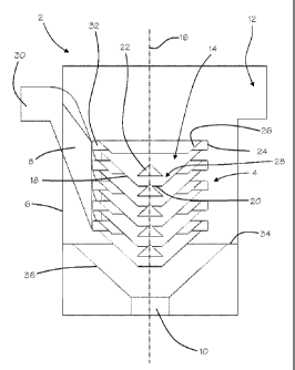
Figure 1 shows a separator 2 comprising a tray assembly 4 disposed within a
treatment
vessel 6. The tray assembly 4 comprises a plurality of nested tray units 14.
Five tray
units 14 are shown in Figure 1, but it will be appreciated that the tray
assembly could
comprise more or fewer tray units 14. The nested tray units 14 define a
separator axis
16, shown in Figures 2, 3 and 5, which is upright and preferably substantially
vertical.
The tray units 14 are spaced apart from each other along the axis 16. The
treatment
vessel 6 is provided with an inlet chute 8, a grit outlet 10 and a fluids
outlet 12.
Each tray unit 14 comprises a frusto-conical tray 18, having a circular
aperture 20 at
the apex of the tray 18, and a baffle 22. The axis of the conical shape of the
tray 18 is
aligned with the separator axis 16. The tray 18 converges in a downward
direction and
the baffle 22 is disposed immediately above the aperture 20. The baffle 22 may
be
supported by the tray 18 by suitable struts and may, for example, be formed
integrally
with the tray 18 or may be supported independently of the trays 18, for
example by a
pole or rod that passes along the separator axis 16. The aperture 20 and the
baffle 22
are aligned with the separator axis 16. The flow area of the aperture 20 is
defined as
the area of the aperture 20. A cylindrical rim 24 extends upwardly from the
outer
periphery of the tray 18 and an annular lip 26 extends radially inwardly from
the
extremity of the rim 24. The radially inward portion of the annular lip 26 is
inclined so
CA 02793943 2012-09-20
WO 2011/117620 PCT/GB2011/050563
as to be parallel to the direction of the upper surface of the tray 18. The
rim 24 and
annular lip 26 may be formed integrally with the tray 18 by a folded over
portion of the
tray 18. The rim 24 and annular lip 26 can be separately manufactured and
assembled
with the tray 18, or can be formed integrally with the tray 18, for example,
when the tray
5 is a plastics moulding.
The baffle 22 comprises a hollow cone having an open base. The diameter of the
base
of the baffle 22 is greater than the diameter of the aperture 20. The baffle
22
converges upwardly, i.e. in a direction opposite to the direction of
convergence of the
tray 18. The baffle 22 thus defines an annular passage 28 between the outer
peripheral edge of the baffle 22 and the conical inner surface of the tray 18.
The
passage 28 is shown more clearly in Figure 5. The width W of the annular
passage 28
is measured perpendicular to the conical inner surface of the tray 18. The
flow area of
the passage 28 is defined as the area of the passage 28 across its width W.
The flow
area of the annular passage 28 is not greater than the flow area of the
aperture 20. It
will be appreciated that the flow area of the annular passage 28 may be
determined in
accordance with the amount of restriction which is to be provided by the
baffle 22 for
particular operating requirements.
Referring to Figures 2 and 3, the inlet chute 8 has a single inlet 30 and a
plurality of
outlets 32. The chute 8 extends into the treatment vessel 6 through an outer
wall of the
treatment vessel 6 and is in direct communication with the tray assembly 4.
The mid-
portion of the chute 8 is inclined in a downward direction from the inlet 30
to the outlets
32. The mid-portion of the chute 8 diverges in a vertical direction from the
inlet 30
towards the outlets 32. The outlets 32 are aligned vertically and extend from
the lower
end of the mid-portion of the chute in a horizontal direction. Each of the
outlets 32 is in
direct communication with a respective tray unit 14 and arranged tangentially
with
respect to the separator axis 16 (shown in Figures 3 and 4). In particular,
the outlets
32 are in direct communication with the region between the annular lip 26 and
the
upper surface of the tray 18.
A plate 34, provided with a funnel section 36, is disposed within the base of
the
treatment vessel 6. The plate 34 extends horizontally across the extent of the
vessel 6
and the funnel section 36 converges in a downward direction. The outlet 10 is
provided
in the lower region of the funnel section 36 and opens into a sump (not shown)
below
the vessel 6. The funnel section 36 is arranged coaxially with the separator
axis 16.
CA 02793943 2012-09-20
WO 2011/117620 PCT/GB2011/050563
6
The separator 2 may be part of a waste water treatment installation, and its
function
may be to separate grit and similar particles from a flow of waste water prior
to further
treatment processes.
During use, the treatment vessel 6 is flooded so that the tray assembly 4 is
submerged.
An influent mixture such as grit entrained by water is supplied though the
chute inlet 30
and flows downwardly along the chute 8 and through the outlets 32 into
respective tray
units 14. The tangential arrangement of the outlets 32 causes the mixture to
circulate
within the tray units 14 about the separator axis 16.
The circulating flow is a relatively low energy flow which allows the
entrained grit to
settle on the upper surfaces of the trays 18. The sloped upper surface of each
tray 18
causes the grit to gravitate towards the aperture 20 in the tray 18. The grit
falls through
the aperture 20 and is diverted radially outwardly by the conically shaped
baffle 22
disposed above an underlying tray 18. The grit settles on the upper surface of
the
underlying tray 18 and gravitates towards and through the aperture 20 of the
underlying
tray 18. The grit passes over the successive baffles 20 and through the
respective
apertures 20 of the underlying trays 18 until it is expelled from the bottom
of the tray
assembly 4. The grit is then discharged from the treatment vessel 6 through
the outlet
10, for example, to the sump (not shown) beneath the vessel 6.
The water from which grit is removed circulates within the tray units 14. The
flow, a
portion of which has a tendency to move upwardly through the apertures 20
towards
the top of the tray assembly 4, is obstructed by the baffles 22. Agitation of
the grit
passing downwardly through the apertures 20 is thus reduced thereby improving
grit
retention within the tray units 14.
As the de-gritted water circulates within each tray unit 14 it flows upwardly
over the
annular lip 26 and over the rim 24 into the outer region of the treatment
vessel 6. The
annular lips 26 thus help to retain grit which has collected on the surface of
each tray
18 within the tray units 14. De-gritted water which collects in the vessel 6
overflows
through the outlet 12. The annular flow passage 28 provides a flow restriction
which
inhibits flow through the respective aperture 20. Restriction of flow through
the
aperture 20 increases the amount of de-gritted water which flows over the
annular lip
26 and rim 24 into the treatment vessel 6.
CA 02793943 2012-09-20
WO 2011/117620 PCT/GB2011/050563
7
Figure 6 shows a variant in which baffles 22 are disposed below respective
apertures
20 in the trays 18. Each baffle 22 projects upwardly through the respective
aperture
20. The flow area of the aperture 20 is the area in the plane of the aperture
20 which is
unoccupied by the baffle 22 of the underlying tray 18.
As shown in Figure 7, each baffle 22 and respective tray 18 defines an annular
passage 29 between the inner peripheral edge of the tray 18 and the conical
external
surface of the baffle 22. The width W of the annular passage 29 is measured
perpendicular to the conical external surface of the baffle 22. The flow area
of the
passage 29 is the area of the passage across its width W. The flow area of the
annular
passage 29 is not greater than the flow area of the aperture 20.
It will be appreciated that other embodiments are possible. For example, a
baffle 22
may be disposed both above and below each aperture 20. One or more of the
baffles
22 may be a flat plate, or other shape suitable for restricting upward flow
through the
apertures 20. Furthermore, the baffle 22 may only partially overlap the
aperture 20, for
example, the diameter of the baffle 22 may be smaller than the diameter of the
aperture 20. This would facilitate removal of the baffle 22 for maintenance
access to
the sump.
The funnel section 36 may extend across the full extent of the vessel 6,
particularly
where the vessel is cylindrical. The funnel section 36 would thus continue
upwardly to
the side walls of the vessel 6.
It will be appreciated that the baffles 22 may be supported independently of
the tray
units 14, for example, by a rod or pole 38, as shown in Figure 10, extending
along the
length of the tray assembly 4. The rod 38 may be tubular to provide access to
the
sump, for example, to provide maintenance access for the removal of grit by a
gully-
sucker or pump connected to the rod.
Figure 8 shows a variant in which a spherical baffle 22 is disposed between
adjacent
trays 18.
CA 02793943 2012-09-20
WO 2011/117620 PCT/GB2011/050563
8
Figure 9 shows a variant in which a spherical baffle 22 is disposed at the
aperture 20 of
each tray 18. The baffles 22 are suspended on a rod 38 which extends along the
separator axis 16.
Figure 11 shows a variant in which an annular baffle 40 projects from the
lower surface
of an upper plate of two adjacent plates 18. The baffle 40 projects in a
direction which
is perpendicular to the surface from which it projects. An annular passage 42
is
defined between the outer peripheral edge of the baffle 40 and the conical
inner
surface of the lower tray 18. The width V of the annular passage 42 is
measured
perpendicular to the inner surface of the lower tray 18. The flow area of the
passage
42 is the area of the passage across its width V. The flow area of the annular
passage
42 is not more than the flow area of the aperture 20 in the lower tray 18. In
use, the
baffle 40 restricts radially inward flow thereby causing more water to flow
over the rim
24 into the outer region of the treatment vessel 6.
Figure 12 shows a variant which is similar to that shown in Figure 11 in which
an
annular baffle 40 projects from a lower surface of the tray 18 in a direction
which is
parallel with the separator axis 16.
Figure 13 shows a variant in which the conical section of each tray 18 is
profiled to
create a flow passage 42 between adjacent trays which converges in a radially
inward
direction. The profiles of the trays 18 are identical. The radially inner
periphery of the
upper tray 18 of adjacent trays and the upper surface of the lower tray 18
form a throat
which defines the minimum flow area of the flow passage 42. The width T of the
throat
is measured perpendicular to the upper surface of the lower tray 18. The flow
area of
the throat is the area of the throat across its width T. The flow area of the
throat is not
more than the flow area of the aperture 20.
Figure 14 shows a variant which is similar to Figure 13, in which each conical
section of
adjacent trays 18 has a stepped profile having a radially outer portion which
is raised
with respect to the radially inner portion. The profiles of the trays 18 are
identical. The
throat is formed in the region in which the raised outer portion of the lower
tray 18
overlaps the non-raised inner portion of the upper tray 18.