Note: Descriptions are shown in the official language in which they were submitted.
CA 02794091 2012-09-21
WO 2011/117580 PCT/GB2011/000416
- 1 -
A SIMULATED CIGARETTE
The present invention relates to a simulated cigarette
comprising a housing having a generally cigarette-like shape
and size; a reservoir of inhalable composition within the
housing; an outlet valve controlling the flow from the
reservoir; an outlet passage from the outlet valve to an
outlet in the housing from which outlet a user inhales the
composition. Such a simulated cigarette will subsequently
be referred to as "of the kind described".
A simulated cigarette of the kind described is
disclosed in our earlier WO 2009/001078 and WO 2009/001082.
These documents disclose a simulated cigarette device
which is refillable in combination with a refill pack which
has a size and shape of a cigarette pack. The user removes
the simulated cigarette from the pack and holds it against
an outlet port in the pack to refill it. This is designed
to mimic the action of removing a real cigarette from a
pack. By replicating the smoking act, the device is more
likely to gain acceptance from a consumer.
However, the simulated cigarette device disclosed in
these applications and, indeed, similar cigarette devices
disclosed in other applications such as US 4,393,884 and DE
4030257 are simply cylindrical plastic tubes.
The present invention aims to provide a simulated
cigarette device which more closely resembles the physical
feel of a real cigarette.
CA 02794091 2012-09-21
WO 2011/117580 PCT/GB2011/000416
2 -
According to a first aspect of the present invention, a
simulated cigarette of the kind described is characterised
in that the housing adjacent to the outlet end has a
deformable material at its outer periphery.
This deformable material is able to be squeezed or
flexed by the index finger and thumb of a smoker. This is
an important feature for a smoker and part of the
behavioural cycle of the smoking ritual. The first aspect
of the present invention therefore provides a tactile sense
akin to a conventional cigarette. Also, the deformable
material provides a more realistic smoking experience for
the user when it comes to inhalation. Users typically purse
inhalation devices with their lips or teeth so it is
advantageous to make the material against which they press
deformable accordingly.
As well as providing increased comfort, the deformable
material can also be used to affect the flow characteristics
of the inhalable composition. Preferably, the deformable
material is configured to be deformable with respect to the
outlet passage to change the flow characteristics from the
outlet passage. With such a deformable material, the user
can disrupt the flow of inhalable material giving rise to
vortices that will modify the delivery from the reservoir.
This mimics the manner in which smokers modify the delivery
of a conventional tobacco cigarette by squeezing the filter
to reduce the pore size thereby modifying the flow of the
smoke accordingly. This allows the user to modify the flow
by narrowing the outlet passage and thereby quickening the
velocity of the flow.
CA 02794091 2012-09-21
WO 2011/117580 PCT/GB2011/000416
3 -
In order to further enhance the control being exercised
by a user, the outlet valve is preferably a breath-activated
valve which is actuated by a flow of air through the housing
in an actuation passage parallel to the flow through the
outlet passage and wherein the deformable material is
positioned so that it is deformable into the housing to a
position in which it affects the flow through at least one
of the actuation passage and the outlet passage so as to
affect the dosage of inhalable composition that a user
receives from the cigarette.
If the user constricts the actuation passage, the
suction force required to open the valve increases while
constricting the outlet passage increases the velocity of
the flow. This is an important adaptable behavioural mode
for smokers since when they desire a deeper inhalation,
normally in a spike of craving, they can modify the suction
chamber through this action and modestly increase the
velocity of the flow, and therefore the speed of uptake to
the lung allowing sophisticated control of the flow
characteristics. Additionally if the user exerts a lower
than usual suction force and constricts the chamber, the
device may function in the opposite manner by creating a
limitation on the breath force exerted on the breath-
activation system and therefore limiting the valve opening
and thus the flow rate by the user. Thus by allowing
distortion of the flow path, akin to a tobacco cigarette, a
more sophisticated control of the flow characteristics is
allowed.
The deformable material may be elastomeric, or may be a
flexible skin containing a fluid or gel.
CA 02794091 2012-09-21
WO 2011/117580 PCT/GB2011/000416
- 4 -
When the deformable material includes liquid or a gel,
as a further enhancement of the invention, this may be
supersaturated and arranged to come into contact with
nucleation sites upon tapping of the cigarette, to form
crystals and undergo an exothermic reaction.
This can produce a warming sensation at the tip of the
cigarette which a user will find pleasant and again
replicates the heating effect in a real cigarette of drawing
smoke through the filter.
As the cigarette device is designed to be refilled a
number of times, there are preferably a plurality of
compartments containing liquid or gel which are separately
actuatable to produce an exothermic reaction.
In addition to, or as an alternative to, using the
exothermic reaction to provide a warm sensation adjacent to
a mouthpiece of a cigarette, the cigarette may be configured
to direct the heat produced inwardly, so as to heat the
inhalable composition in the outlet passage.
This forms a second aspect of the present invention
which may be defined, in the broadest sense, as a simulated
cigarette of the kind described further comprising a
chemical heater provided adjacent to the outlet passage and
arranged to be activated to undergo an exothermic reaction
to heat the inhalable composition as it travels along the
outlet passage.
CA 02794091 2012-09-21
WO 2011/117580 PCT/GB2011/000416
-
The generation of heat in a simulated cigarette is
known, for example, in EP 1 618 803 and in WO 2009/155957.
However, in these cases, the heat is used to vaporise the
composition. In this second aspect of the present
5 invention, the inhalable composition is released from a
reservoir and is subsequently heated by a heater.
The inhalable composition is released from the
reservoir will generally be cold. It is warmed, to some
extent, by the surrounding housing as it travels around the
outlet passage and, if present, by dilution of air from the
actuation passage. However, if the device is used
repeatedly, the mouthpiece itself can become cold to touch.
This can be avoided by heating the mouthpiece, which also
has a beneficial effect on the temperature of the inhalable
composition flowing through the mouthpiece.
Preferably, the outlet valve is at least 4mm from the
outlet. This allows sufficient time for the inhalable
composition to mix with ambient air to allow the warming
effect referred to above. This allows sufficient time for
the inhalable composition to mix with ambient air to allow
the warming effect referred to above.
Preferably, the heater is provided by a gel or liquid
which is supersaturated and which is arranged to come into
contact with nucleation sites upon tapping of the cigarette,
to form crystals and undergo an exothermic reaction.
As the cigarette device is designed to be refilled a
number of times, there are preferably a plurality of
compartments containing liquid or gel which are separately
CA 02794091 2012-09-21
WO 2011/117580 PCT/GB2011/000416
- 6 -
actuatable to produce an exothermic reaction. These
components are preferably provided by rupturable
microcapsules.
According to a third aspect of the present invention, a
simulated cigarette of the kind described is wrapped in a
wrap comprising an adhesive layer to stick to the housing, a
paper or paper-like layer and a polymer film to cover and
protect the paper or paper-like layer.
In the prior art referred to above, all simulated
cigarettes of this type have only a plastic housing as they
are designed to be durable. US 2004/0003820 discloses a
cigarette substitute with a chamber lined with a scratch-
releasable-coated paper which is scratched with a wire brush
to release a cigarette-like aroma. This document discloses
that the vessel is coated or lined with a white, paper-like
material for improved realism but there is no indication of
the underlying material of the housing, or how this is
implemented. JP2010/35663 discloses an inhaler containing a
string of capsules. These are crushed by a user's fingers
to release their contents for inhalation. The device is
covered in a paper-like material as it is required to be
deformable to crush the capsules.
The third aspect of the present invention replicates
more closely the feel of a real cigarette. Further, it is
suited to the arrangement described in WO 2009/001078 which
is designed to be refilled only a relatively small number of
times such that longevity is less of an issue. The polymer
film is able to protect the paper as the time for which it
is used, while for less than the prior art above, is still
CA 02794091 2012-09-21
WO 2011/117580 PCT/GB2011/000416
- 7 -
significantly longer than a real cigarette or the devices of
US 2004/0003820 and JP 2010/035663.
Preferably, the wrap is hydrophobic so that it does not
absorb moisture from the user's mouth, from the ambient
environment or from the filling process. The wrap is
preferably a wipe-clean paper. It is preferably also fire
retardant in case of hazard or mistaken ignition.
Preferably, the wrap is provided with a flavour (e.g.
menthol) and/or an antibacterial agent.
Such an example of a wrap is a co-extruded biaxially
orientated corona treated polyproplyene situated with an
acrylic based adhesive. The adhesive is a water-borne
acrylic based adhesive comprising acrylic esters
copolymerised with acrylic acid.
This is laminated over a supercalendered glassine
paper, which gives the image and texture of a paper wrap,
where the transparency is around 30-60%, most preferably
45%. A compatible ink, preferably a raw material consisting
of an acrylate mixture, which in its finished cured form in
a acrylate polymer contains very little residual monomer
such to improve the chemical stability of the system. Such a
system can also be impregnated with Silver Ion spray coating
on top of the glassine paper to limit any microbial
activitiy over continued use, and the end tip can be sprayed
with a compatible fire retardent material before the
adhesive layer and extruded polyproplyene applied.
Additionally a laminate is layered over the system to
improve stability and use duration. A higher strength
CA 02794091 2012-09-21
WO 2011/117580 PCT/GB2011/000416
8 -
acrylic adhesive is employed to attach the laminate underlay
of the glassine paper to the plastic chassis tubing of the
inhaler, such that it will remain in fixed position without
uncurling or unwrapping over the alotted shelf life. Such a
system should incorporate as low a density co-extruded
biaxially orientated corona treated polyproplyene as
possible without compromising resistance, in order to
improve the fixation stability of the wrap.
The system should comply with the guidelines laid down
under ISO 10993 when relating to component biocompatibility.
As such, plastic coating should comply with a material
safety test guidance under the European Pharmacopiea in
order to ensure compatability with transient oral mucocal
contact, with adhesive layers ensuring compatability with
the European food directive legislations, FDA 175.105 and
the German recommendations XIV as published by BfR. This
construction should also be classed as a safe product in
accordance with the material description as given by EC
directive 92/59, article 2(b) which will ensure safety for
repeated use.
The wrap may be used in its own right, but is
particularly advantageous when used in combination with the
deformable material of the first aspect of the present
invention and/or the heater of a second aspect of the
present invention, as the overall effect most closely
resembles a real cigarette.
In all aspects of the invention, the reservoir is
preferably pressurised and is preferably refillable. The
CA 02794091 2012-09-21
WO 2011/117580 PCT/GB2011/000416
- 9 -
refill is preferably carried out through a refill valve at
the end of the cigarette opposite to the outlet.
Examples of a simulated cigarette in accordance with
the various aspects of the present invention will now be
described with reference to the accompany drawings, in
which:
Fig. 1 is a cross-section of a simulated cigarette;
Fig. 2 is an exploded view of the simulated cigarette;
Figs. 3A to 3C are perspective views of alternative
deformable members; and
Fig. 4 is a cross-section of the Fig. 3A example.
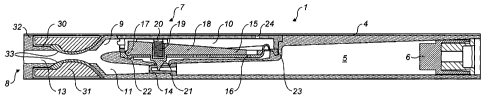
The device has a housing 1 made up of a main chassis 2
and a closure element 3 as shown in Fig. 2. This is held in
place by label 4. Within the housing, there is a reservoir
5 containing the inhalable composition. This is preferably
pressurised but could also work with a non-pressurised
reservoir in combination with a Venturi nozzle to generate
an enhanced suction force on the reservoir. It may be
refillable as described in WO 2009/001082 through the
filling valve 6, or the device may be a single use device,
or may be arranged so that the reservoir 5 is a replaceable
component.
The breath-activated valve 7 is positioned between an
outlet end 8 and the reservoir 5. The breath-activated
valve is arranged so that, when a user sucks on the outlet
end 8, the breath-activated valve 7 opens to allow the
inhalable composition from the reservoir 5 to be inhaled.
CA 02794091 2012-09-21
WO 2011/117580 PCT/GB2011/000416
-
The housing downstream at the valve 7 has two
passages. The first of these is the suction passage 9 which
communicates with a chamber 10 as will be described in
greater detail below and the second is a composition passage
5 11 from which the inhalable composition is dispensed. This
is also described in more detail below. The suction passage
and composition passage meet at outlet passage 13 which
leads to outlet end 8.
10 A deformable tubular nozzle 14 is provided between the
reservoir 5 and composition passage 11. The element is
selectively deformable between open and closed
configurations by a mechanism as described below.
This mechanism comprises a pivotally mounted vane 15
and a membrane 16. The pivotally mounted vane has a pivot
17 at the end closest to the outlet end 8 and a central
reinforcing rib 18 running along its length and tapering
away from the outlet end. At around the midpoint, the vane
15 is provided with a recess 19 for receiving a spring 20
which biases it into the closed position shown in Fig. 1.
Below the recess 19 is a jaw 21 having a triangular cross-
section which is configured to apply the force provided from
the vane 15 to the nozzle 14 over a narrow area (although
the nozzle is shown in Fig. 1 in its uncompressed, open
state, whereas in use, with the vane in this position it
would deform the nozzle to seal the reservoir). The vane 15
is supported by the diaphragm 16 which is sealed to the
housing at its ends 22, 23.
An inlet 24 is provided into the chamber 10, while the
underside of the membrane 16 is open to atmospheric pressure
CA 02794091 2012-09-21
WO 2011/117580 PCT/GB2011/000416
- 11 -
as a leakage path exists through the housing 1 which is not
shown in the drawings as it is not shown in the plane of
Figs. 1 and 2.
When a user sucks on the outlet end 8 air is sucked
through inlet 24 through chamber 10 and out of suction
passage 9 thereby lowering the pressure in the chamber 10.
This causes the vane 15 to be lifted against the action of
the spring 20 deforming the diaphragm and lifting the jaw 21
to allow the deformable nozzle 14 to open, thereby allowing
the inhalable composition from the reservoir 5 along
composition passage 11 into the outlet passage 13 where it
mixes with the suction air. The degree of suction applied
by the user will determine the extent to which the vane 15
moves and therefore the amount of composition that the user
receives. As soon as a user stops sucking, atmospheric
pressure will return to the chamber 10 and the spring 20
will push the vane down thereby pinching the nozzle 14
closed.
The simulated cigarette described to date is generally
as described in WO 2011/015825.
The housing 1 is provided at the outlet end with a
generally annular recess 30 surrounding the outlet passage
13. Within this annular recess is a deformable member 31
which, in situ, is flush with the surface of the housing 1
as shown in Fig. 1. The deformable member 31 may be an
elastomeric member, or may be a thin-walled capsule
containing a liquid or gel which is described in more detail
below. An annular lip 32 is present at the outlet end of
CA 02794091 2012-09-21
WO 2011/117580 PCT/GB2011/000416
- 12 -
the cigarette. This may be thinner than the illustrated
lip, or may not be present at all.
The deformable member 31 is generally positioned in the
area that would be occupied by the filter of a conventional
cigarette. Thus, the user is able to squeeze the end of the
cigarette in the manner that they would squeeze the filter
of a cigarette, and hold this end of the cigarette in their
mouth and, in both cases, obtain a tactile sensation
comparable to that of a real cigarette.
Further, the housing 1 in the vicinity of the outlet
passage 31 is provided with a pair of diametrically opposed
openings 33 and, as shown in Fig. 1, the deformable member
31 is arranged to bulge through these to project into the
outlet passage 13. As the user presses on the deformable
member, the degree to which the deformable member bulges
into the passage 13 is varied. If the user presses on the
top of the deformable member 31 (with reference to the
orientation shown in Fig. 1), they will restrict the flow
through the suction passage 9 with the effect that the user
will need to suck harder on the device to achieve the
desired inhalation profile. If they press on the lower part
of the deformable member 31, they will restrict the flow
through the composition passage 11 with the effect that if
the valve is fully open, the velocity of the flow will
increase and quicken the route of delivery. Pressing on the
top and bottom of the deformable member 31 simultaneously
will increase the resistance and necessatitate sucking
harder on the device but also by nature of construction of
the composition passage 11, quicken the flow and speed of
delivery. This is a useful feature for smokers who wish to
CA 02794091 2012-09-21
WO 2011/117580 PCT/GB2011/000416
- 13 -
quicken the rate of absorption when undergoing a spike in
craving. Thus a user is able to self-regulate the flow of
inhalable composition from the cigarette, much as they are
able to do with a conventional cigarette by squeezing on the
filter.
As well as providing tactile benefits, and the ability
to regulate the flow, the deformable member 31 may also be
designed as a heater.
As mentioned above, the deformable member 31 may
contain liquid or gel. This may be an acetate, and
preferably sodium acetate that is super saturated. This may
be encapsulated into microcapsules having a polymeric or
celluostic casing. If there are around 20 such
microcapsules, the device can be re-used a number of times,
each time breaking a small number of the capsules. Inside
the deformable member 31 and surrounding the inner wall is a
layer, disc or film of ferrous metal or other that have been
coursed to provide a greater reactive surface area. When
the user taps the outer wall of the deformable element 31,
such as a smoker is accustomed to do to release ash that has
built-up on the tip of the cigarette, crystals of sodium
acetate are released into the solution which then act as
nucleation sites. This causes the solution to crystallise
suddenly, releasing energy and thereby creating a heating
effect to the surrounding material, which the user can
perceive. This heat can be controlled to ensure that the
temperature is pleasant and warming and does not approach
higher temperatures that may impact on the integrity of the
device. In order to last over several refills of the
device, the deformable member 31 may be composed of multiple
CA 02794091 2012-09-21
WO 2011/117580 PCT/GB2011/000416
- 14 -
layers or compartments 34, each connected individually to
separate solutions and ferrous metals. It is possible that
the outer wall of the deformable member 31 may be a good
insulator which allows minimal heat to be conducted out of
the device so that the heat is, instead, directed inwardly
to heat the flow through the upper passage 13.
Alternative designs of deformable element 31 are shown
in Figs. 3A-3C and 4. In Figs. 3A and 4, a plurality of
frangible balls 35 containing acetate are each positioned on
.a ferrous disc 36 which provides the nucleation sites.
Pressure on the outer wall of the deformable member breaks
some of the frangible balls so that the acetate comes into
contact with the ferrous disc initiating nucleation and
causing an exothermic reaction.
In Fig. 3B, the compartments 34 are filled with calcium
powder and frangible balls 37 containing water are arranged
along the length of each compartment. Again, pressure on
the deformable member 31 breaks the balls 37 and the water
and calcium chloride react exothermically.
In Fig. 3C, each compartment 34 contains an elongate
ferrous disc 38, the compartment filled with acetate. In
this case, pressure on the deformable member 31 causes a
sudden "snap" deformation of a disc 38 to trigger
nucleation.
Other chemical heating sources for example can include,
but not limited to, utilising an in situ combination of
calcium chloride and reservoir containing pure distilled
water. The calcium chloride is separated from water by a the
CA 02794091 2012-09-21
WO 2011/117580 PCT/GB2011/000416
- 15 -
film or a diaphragm which when tapped or pushed, loses the
integrity of its casing and allows the water to dissipate
and therefore causing an exothermic reaction to take place.
For use in a multi-phase manner, the distilled water can be
manufactured into microcapsules, pellets or spheres
encompassed either a polymeric or cellulosic casing that are
no more than 2mm in diameter. These microcapsules can be
located within the chamber and distributed evenly around a
surrounding layer of finely milled calcium chloride powder.
When a user squeezes the deformable member 31, element of
the mouthpiece, pressure is applied to the microcapsules
such that they casing ruptures and releases its containment
of the distilled water. There can be arranged around 20
microspheres within the deformable chamber such that there
scope for multi-activation during the use of the cigarette
device.
As can be seen in Fig. 1, the jaw 21 which represents
the effective outlet from the reservoir 5 is positioned some
considerable distance from the outlet end 8. This distance
is preferably greater than 10mm. This means that the
composition has to flow a reasonable distance through the
device before it is inhaled by the smoker. Thus, it can be
warmed by the housing surrounding the composition passage 11
and outlet passage 13. It is diluted and warmed by the air
from the suction passage 9 and is also heated by the heat
generated in the deformable member 31 if this is designed as
the exothermic element described above. The smoker
therefore inhales composition which is warmed to a degree
ideally replicating the temperature of smoke from a real
cigarette, but at least warmed to a degree so as not to
cause discomfort.
CA 02794091 2012-09-21
WO 2011/117580 PCT/GB2011/000416
- 16 -
The label 4 is an overwrap that surrounds substantially
the entire curved surface of the simulated cigarette. As
shown in Fig. 2, it is divided into two sections 40 and 41
which are coloured and patterned to resemble a conventional
cigarette with a filter tip. In combination with the
deformable member 31, the outlet end of the cigarette both
looks and feels like the filter of a conventional cigarette.
The label has at least one hole laser drilled so as not to
obstruct inlet 24.
The coatings applied to the label 4 demonstrate
hydrophobic properties, but also create a lipophobic and
oleophobic surface to repel water, dirt on surfaces and any
formulation that may be spilled or accidentally emitted
during the refilling process. This makes sure that the
cigarette paper does not tear or blemish as the formulation
may contain propylene glycol, PEG or aromatic oils which
will lead to quick discolouration of the paper, and reduce
its structural integrity. As such coatings can be used such
as a phosphonate based application, and applied in a
monolayer. This can be provided by for example Aculon Inc.
This will also impart an additional wipe clean quality, so
that the dirt does not build up on the mouthpiece. Since the
device is intended to be disposable, a coating can be
applied solely to the mouthpiece and to the distal end where
the refill valve is, to reduce the likelihood of dirt
ingress and paper tear. This also provides an enhanced
consumer response so that users can clean the mouthpiece end
easily without fear or paper or fabric tear, for example if
lipstick is accidentally applied.
CA 02794091 2012-09-21
WO 2011/117580 PCT/GB2011/000416
- 17 -
Additionally fluropolymers can be used, either applied
directly to the paper or fabric coating as a powder or spray
and provide necessary oil-repellant/water-repellant
properties. These can include PTFE
(polytetrafluoroethylene), PFA (perfluoroalkoxy polymer
resin), FEP (fluorinated ethylene-propylene) and
ETFE polyethylenetetrafluoroethylene but not limited to
these types of fluoropolymers. Care is taken when choosing a
coating that they demonstrate suitable biomaterial
compatibility especially if in frequent contact with the
skin.
The wrap may be paper-like material such as a tightly
woven cotton, or other fabric and a coating of silica or
titania particles can be used to provide hydrophobic
properties on devices where the oleophobic property is not
needed due to a different composition of formulation.
Preferably a material is used that contains a
hydrophobic, lipophobic and oleophobic property but also has
a fire retardant capability. This is to protect the device
in case it unduly exposed to fire or naked flame. Such
coatings can include Aluminium Trihydride (ATH), Antimony
Trioxide (Sb203) and Zinc Borate. Zinc Oxides can also be
used at a pharmaceutical grade specifications for use in
this respect.
A specialty chemical, MP Protect, available at ISC Ltd,
can also be applied which incorporates a fire retardant
system for cellulose rich substrates, such as wood, paper
cotton and certain textile applications. This will allow it
to be capable of withstanding flames in accordance with the
CA 02794091 2012-09-21
WO 2011/117580 PCT/GB2011/000416
- 18 -
DIN 53438 standard burn test, but also has a property to
impart an anti-bacterial quality which can destroy micro-
organisms such as influenza, salmonella and Legionella. This
can be an important attribute to the device if shared
routinely in social situations.
An anti-bacterial coating on the mouthpiece may be
especially advantageous as part of one coating or in
addition to several coatings but locally applied on the
mouthpiece. Such coatings can include a thin layer of
silver, Ionizable silver incorporated into fabric, silver
alloy or oxide which will help in reducing the bacteria
spread and have been approved for use in respiratory devices
such as endotracheal breathing tubes by the FDA. This will
offer an improved hygienic aspect to the device if used
multiple times before it is eventually disposed of.