Note: Descriptions are shown in the official language in which they were submitted.
I
CA 02794119 2016-11-30
- 1 -
Thermographic test method and testing device for
carrying out the test method
BACKGROUND OF THE INVENTION
The invention relates to a thermographic test method
for the locally resolving detection and identification
of defects near the surface in a test object and to a
testing device suitable for carrying out the test
method.
Semifinished products of electrically conductive
material, for example billets, bars, rods, tubes or
wires of metallic materials, may serve as starting
materials for high-grade end products and often have to
meet extremely high quality requirements. The testing
for material defects, in particular for defects near
the surface such as cracks, voids or other
inhomogeneities in the material, forms an important
part of the quality control of these products. During
this testing, it is generally endeavored to test the
surface of the material as completely as possible with
high local resolution, which wherever possible is
carried out as early as possible in the production
chain in order to decide on the basis of the result of
the test, depending on the type of defects found,
whether the defects are uncritical for the further
processing, or at least can be repaired by reworking
such as grinding, or whether the material has to be
discarded.
Apart from the magnetic methods that are often used for
such tests, such as the eddy current technique or the
stray flux technique, nowadays thermographic test
methods are also used for the locally resolving
detection and identification of defects near the
surface in test objects.
h
CA 02794119 2016-11-30
- 2 -
In a known thermographic test method, an electrically
conducting test object, for example a steel billet,
after rolling runs through an induction coil that is
under high-frequency alternating current and induces a
current flow near the surface of the test object. On
account of the skin effect, which is dependent on the
excitation frequency, the current density in the
vicinity of the surface of the test piece is greater
here than inside the test object. Microstructural
disturbances, such as for example cracks, that lie in
the cross section of the induced electrical current
flow act as electrical resistances and deflect the
current flow, which tries to find the path of least
(electrical) resistance in the material of the test
piece. This results in higher current densities, and
consequently also greater power losses, at the
"constrictions" of the current flow in the region of
the defects. The power loss occurring in the region of
the microstructural disturbances is manifested by heat
being generated in such a way that the, locally
limited, affected region in the direct vicinity of a
microstructural disturbance assumes a higher
temperature in comparison with the undisturbed
surrounding area. With the aid of a heat-sensitive
camera or other suitable recording device that is
sensitive to thermal radiation, the presence of defects
near the surface can then be detected in a locally
resolving manner on the basis of the local temperature
values within a region of the surface that is recorded
by the recording device. A visual representation of the
surface regions recorded is generally also provided,
and thermographically determined anomalies can be
automatically assessed by a downstream evaluating
system.
1
I'
CA 02794119 2016-11-30
- 3 -
DE 10 2007 055 210 Al describes a thermographic test
method and a testing device set up for carrying out the
test method. The testing device has an induction coil
for heating up a surface area of a metallic test object
running through the induction coil, for example a steel
billet, and one or more infrared cameras, in order to
measure the temperature profile of the steel billet
running through. The results of the measurement are
used for activating a color marking system, in order to
mark defects that are found. For the evaluation of the
thermographic images (thermal images) recorded by the
infrared cameras, the description provides evaluation
software, which analyzes a thermal image or the thermal
images and identifies temperature differences above a
predetermined threshold value and reports them as a
defect. The size of the temperature difference above
the predetermined threshold value is regarded as an
indication of the depth of the defect. The evaluation
software can evaluate defects both with regard to their
length and with regard to the size of the temperature
difference above the threshold value. The evaluation
software can remove defects of a length below a minimum
defect length from a defect list, so that such defects
are no longer found to be defects. If, however, a
defect lies below a minimum defect length but the size
of the temperature difference lies above the threshold
value, which lies above a maximum size of the
temperature difference, such a defect is nevertheless
reported as a defect. In this way, a defect is
identified in dependence on the defect length and the
temperature difference with respect to the surrounding
area.
A rise in the temperature profile of more than 2 K with
respect to the surrounding area is generally regarded
as a defect, but the threshold temperature may also be
chosen to be lower. A temperature difference with
11
II
CA 02794119 2016-11-30
- 4 -
respect to the surrounding area of 5 I< or more is
clearly identified as a defect.
In practice, the temperature profile to be evaluated is
generally superposed by an interference signal of an
appreciable amplitude. Possible sources of interference
include local fluctuations in the degree of emission of
the surface of the test object, reflections from the
surrounding area and circumstances that are generally
unavoidable in actual test operation, such as foreign
bodies on the surface of the test piece. False
indications may also be caused by the geometry of the
test piece, since for example edges on square profiles
often have an increased temperature in comparison with
the surrounding area. Typically, the temperature
differences occurring at a crack-like defect in
comparison with the surrounding surface are of the
order of magnitude of 1 K to 10 K. It has been observed
that interference amplitudes may well also be of this
order of magnitude. Therefore, in spite of all possible
measures to reduce the interference amplitude, it
cannot be ruled out that interferences are falsely
classified as microstructural flaws or defects.
PROBLEM AND SOLUTION
A problem that is addressed by the invention is that of
providing a thermographic test method and a
thermographic testing device suitable for carrying out
the method that offer improved suppression of
interference in the evaluation of thermographic signals
in comparison with the prior art. In particular, it is
intended to improve the selectivity in distinguishing
between actual defects and pseudo-defects attributable
to other interferences. It is preferably intended to
provide testing of the complete surface of elongated
objects of electrically conductive material with
il
h
CA 02794119 2016-11-30
- 5 -
increased reliability in the detection and
identification of defects.
To solve this and other problems, the invention
provides a thermographic test method and a
thermographic testing device set up for carrying out
the method.
In the test method, a portion to be tested of the test
object is exposed to the effects of a heating device.
Hereafter, this is also referred to for short as
"heating up". The heating energy is in this case
introduced in such a way that a thermal disequilibrium
occurs between defective regions, affected by defects,
or flawed locations and the material of the test piece
that is free from defects. A flawed location or a
defective region in this case includes the actual flaw,
for example a crack, and the directly adjacent
surrounding area. The defect-free surrounding area may
possibly maintain its temperature under the effect of
the heating device, that is to say not be heated up, or
it may be heated up less intensely than the flawed
locations.
In the case of electrically conductive test objects,
such as for example metallic billets, bars, wires or
the like, an inductive method may be used for example
for the heating-up process. The input of thermal energy
into the defective regions of the test object may also
take place with the aid of ultrasound.
Within a heat propagation phase, a series of two or
more thermographic images is recorded, these being
recorded at time intervals from one another. The heat
propagation phase begins when the heat flow from the
locally heated-up defective region into the surrounding
area manifests itself. The heat propagation phase
11
CA 02794119 2016-11-30
- 6
extends into the cooling-down phase following the
heating-up process and in many cases corresponds to the
cooling-down phase. However, there is often no strict
limit between the heating-up phase and the cooling-down
phase. The beginning of the heat propagation phase may
still overlap in time with the phase of the local
heating up, since thermal energy can already propagate
during the heating-up process.
Each of the thermographic images in this case
represents a local temperature distribution in a
surface region of the test object recorded by the
thermographic image at different points in time during
the heat propagation. If the recording device provided
for recording the thermographic images, for example a
thermal-imaging camera, and the test object are at
rest, the surface regions of the test object recorded
at different points in time may be identical. If there
is a relative movement between the test object and the
recording device, the surface regions may be spatially
offset in relation to one another.
Positionally correctly assigned temperature profiles
are determined from the thermographic images of a
series, each of the temperature profiles that are
assigned to one another positionally correctly being
assigned to the same measuring region of the surface of
the test object. The term "measuring region" refers
here to a one-dimensionally or two-dimensionally
extended region that has a fixed position in the system
of coordinates of the test object. Many measuring
positions lie in the measuring region.
The term "temperature profile" refers to a locally
resolving profile in which different locations or
positions within the temperature profile are
respectively assigned values of a measured variable
u
CA 02794119 2016-11-30
- 7 -
that represent the temperature at the respective
location. The temperature profile may be understood as
a location function, which describes the dependence of
the temperature value on the location within the
temperature profile. A temperature profile may, in the
manner of a line profile, relate to a more or less
narrow, almost linear region. It may also concern a 2D
profile or area profile, the local distribution of
temperature values in a piece of area of a
predetermined shape and size then being described by
the temperature profile. The measured variable assigned
to the different locations of the temperature profile
may be referred to as the "temperature value". This
does not generally involve measuring the temperature
directly, but for example measuring the intensity or
amplitude of the thermal radiation emitted by the
respective location, which can be converted into a
local temperature of a profile location by the means
that are customary in thermography.
In this way, a number of temperature profiles (at least
two) are determined, representing the local variation
in temperature within the same measuring region at
different points in time during the cooling-down
process. The variations over time of temperature values
are then quantitatively determined from the temperature
profiles for a large number of measuring positions of
the measuring region that are recorded by the
temperature profiles, so that the development over time
of the local temperature values is obtained for a large
number of measuring positions of the measuring region.
The variations over time are then evaluated on the
basis of at least one evaluation criterion that is
suitable for characterizing the heat flow in the
measuring region.
11
h
CA 02794119 2016-11-30
- 8 -
In the method, not only are the temperature profiles
analyzed with regard to the local variation in
temperature represented by them, but also their change
over time. A sequence or a series of temperature
profiles is obtained for a defined measuring region at
the surface and a defined time range. An essential
aspect of the method is the inclusion of the heat flow,
that is to say the dynamic behavior of the development
over time of the temperature profile and the evaluation
or interpretation thereof.
Another formulation consequently proposes the use of a
variant of the locally resolving heat flow thermography
for the detection and identification of defects near
the surface in suitable test objects, the development
over time of the local distribution of the temperature
that can be found at the surface of the test piece
being determined and evaluated. This involves, inter
alia, quantitatively recording and evaluating the
lateral heat flow.
In comparison with the prior art, a much more reliable
classification of defects, for example as a crack or a
microstructural disturbance, is obtained, since the
method allows an improved capability of distinguishing
between temperature effects that are attributable to
defects and effects that are not caused by heat flow.
Furthermore, an improved capability of evaluating the
thermographic information is obtained, even in the case
of low signal amplitudes, since it is not just the
amplitude or the intensity of the temperature signals
in the profiles that is decisive but also how they
dynamically behave on the time axis. This also results
in considerably improved interference suppression even
when the interference amplitude (not attributable to
the defects sought) is higher than the useful signal
amplitude, the useful signal amplitude referring here
II
h
CA 02794119 2016-11-30
- 9 -
to the signal amplitude caused by microstructural
disturbances.
The test method particularly allows the spatial-
temporal heat propagation after a sudden, locally
limited influx of heat to be recorded and
quantitatively evaluated. In simple terms, the spatial-
temporal heat propagation takes place in such a way
that the heat concentrated in the region of a potential
defect flows away over time into neighboring, cooler
regions of the material of the test object. The flowing
away is manifested by a lateral surface temperature
distribution insofar as a temperature profile at the
point of excitation decreases in amplitude over time,
but there is a noticeable increase in temperature in
the direct vicinity of the excitation position. It
follows from this that, under these conditions, the
shape of the temperature profiles changes over time in
a characteristic manner. The most frequent interfering
influences, for example surface reflections, on the
other hand, do not undergo any change, or only a small
change, over time with respect to their local
properties and/or show a change over time that deviates
distinctly from the typical heat flow behavior (for
example brief flashing of a reflection). Such
interfering influences can therefore be clearly
distinguished from actual defects on the basis of their
typical spatial-temporal behavior. Some interfering
influences are indeed manifested in the temperature
profile by dynamic spatial-temporal behavior, but this
generally differs distinctly from the spatial-temporal
heat propagation that takes place in the surrounding
area of a defect within a heat-conductive material
undisturbed by interference. Therefore, an evaluation
which analyzes the spatial-temporal behavior of
temperature profiles from the aspects of the laws of
heat propagation or heat diffusion in a solid body
,,
h
CA 02794119 2016-11-30
- 10 -
offers much improved selectivity and interference
suppression in comparison with conventional methods.
The evaluation can therefore also be described as
comprising in the evaluation a comparison of the
recorded thermographic data with a signature, the
signature being a description of the spatial and
temporal heat propagation in a solid body that
endeavours, especially after a local concentration of
heat, to re-establish the thermal equilibrium.
In a preparatory evaluation step, the temperature
profiles are preferably automatically analyzed for
whether defect-like anomalies are evident in the
temperature profile, that is to say anomalies that
could be attributed to a defect, but not necessarily.
In the identification of defect-like anomalies,
preferably a local maximum of the temperature values
within the temperature profiles is sought. The local
maximum corresponds here to a location within a
temperature profile of which the temperature is
distinctly higher than the temperature at profile
locations in the directly surrounding area of the local
maximum. The identification step is intended, for
example in crack testing, to find substantially narrow
hot locations in an otherwise cooler surrounding area.
In this identification step, suitable image-processing
filter routines may be used, in order for example to
distinguish a local maximum from edge locations at
which the temperature increases or decreases abruptly
or in a step-like manner, as it were, over a short
distance from one side of the surrounding area to the
other side of the surrounding area. Generally, two or
more filter routines operating on the basis of
different criteria are used for this purpose, in order
to identify those image locations (pixels or pixel
11
h
CA 02794119 2016-11-30
- 11 -
groups) that are clearly attributable to a local
temperature maximum.
The evaluation can then concentrate on those regions in
which local temperature maxima have been found. In a
method variant, the variation over time of the
amplitude of a temperature value in the region of a
local maximum of the temperature values of a
temperature profile is evaluated as the evaluation
criterion. This can be used for example to determine
the cooling-down rates in the region of the local
maximum and in the vicinity thereof. It has been found
that cooling-down rates in the region of
microstructural disturbances, such as cracks, within an
otherwise undisturbed surrounding area can be well
described by laws of heat diffusion and, as a result,
can be used as a reliable assessment criterion. Cracks
and other defects can therefore often be distinguished
from disturbances not attributable to defects just on
the basis of the typical cooling-down rates.
Alternatively or in addition, in the evaluation a heat
volume concentration value in the region of a local
maximum of the temperature values within a temperature
profile may be determined and the variation over time
of the heat volume concentration value evaluated. The
heat volume concentration value is a measure of how the
volume of heat of the local maximum relates in
comparison with the directly surrounding area. If this
heat volume concentration falls over time, heat flows
away into the surrounding area, as is typical for
example in the surrounding area of cracks. If, on the
other hand, the local maximum is not attributable to a
microstructural disturbance or a crack, the heat
concentration value often shows significantly different
behavior, it even being possible for example for the
heat concentration to continue initially to increase
,,
h
CA 02794119 2016-11-30
- 12 -
after the heating-up process has been ended. This is
then an indication that the local temperature maximum
is not attributable to a crack or the like.
In order to be able to determine with sufficient
accuracy appropriate time functions for the evaluation
of the variations over time by way of calculated
characteristic variables, in preferred embodiments at
least three temperature profiles recorded one after the
other in time are evaluated together, in order to
obtain a suitable number of interpolation points.
Generally between four and ten temperature profiles are
evaluated together, so that there are an adequate
number of interpolation points in the time domain and a
reliable distinction can be made between defects and
artefacts.
Alternatively or in addition to the determination and
evaluation of characteristic variables from time
functions, it is also possible to perform the
variations over time of temperature values within the
temperature profiles on the basis of image elements
(pixels) or groups of image elements (pixel groups).
The results are then brought into relation to one
another in order to arrive at spatial-temporal
signatures. Generally, every variant of signal
evaluation that allows dimensional figures or data for
a comparison of the signal properties with the
theoretical principles of heat propagation in a solid
body can be applied. For example, spatial-temporal line
profiles, recording sequences, pieces of areas, any
desired pixel arrangements or pixel patterns may be
used. What is essential is joint consideration or
inclusion of the spatial and temporal aspects, without
which it would scarcely be possible to make a reliable
statement as to defect probabilities.
I
ii
CA 02794119 2016-11-30
_
- 13 -
It is possible to use the test method in testing
devices in which both the test object and the recording
device for recording thermographic images are at rest.
This simplifies the positionally correct assignment of
the temperature profiles to one another considerably,
since the same measuring region in thermographic images
recorded one after the other in time respectively
corresponds to the same image region (same image
coordinates) in the thermographic images.
In preferred applications, however, the test method is
used for testing elongated test objects, such as for
example bars, tubes, wire or the like. For testing
elongated test objects, a relative movement may be
produced between the test object and a recording device
for recording the thermographic images parallel to a
direction of movement, which expediently extends
parallel to the longitudinal direction of the elongated
test object. In this case, the recording device is
preferably at rest, while the test object is moved in
relation to the recording device. The relative movement
is produced in such a way that the surface regions that
have respectively been recorded by the thermographic
images recorded one after the other in time are
arranged offset by a specific distance parallel to the
direction of movement. The surface regions recorded
directly one after the other in time in this case
preferably overlap partially in such a way that each
location of the surface under test is recorded by two
or more thermographic images. As a result, testing of
the complete surface of elongated test objects moving
in the longitudinal direction is possible. Preferably,
each location of the surface of the test piece occurs
in three or more thermographic images, for example in
four to twenty or more thermographic images, the
location lying at a different point (image position) in
1
h
CA 02794119 2016-11-30
- 14 -
each of the thermographic images on account of the
relative movement.
The positionally correct assignment of temperature
profiles of different thermographic images represents a
particular challenge in the testing of moving test
objects. In a variant of the method, a first
thermographic image, recorded at a first point in time,
of a series of thermographic images is analyzed by
image processing, in order to identify at least a first
selected image detail that contains thermographic data
of a first surface detail with a defect-like anomaly.
The identical surface detail is then automatically
found in a second image detail corresponding to the
first image detail. The second image detail is located
in a second thermographic image, recorded at a time
interval from the first thermographic image at a later,
second point in time. Then a joint evaluation of the
thermographic data of the first and second image
details takes place, in order to achieve the
positionally correct assignment.
For automatic finding, an expected position of the
surface detail containing the defect-like anomaly in
the second thermographic image is preferably determined
on the basis of a measured, or in some other way known,
relative speed between the test object and the
recording device and the time interval that has passed
between the first point in time and the second point in
time, in order to determine that path that the surface
detail has covered in the direction of movement between
the first point in time and the second point in time.
This allows the evaluation of the second thermographic
image to concentrate from the beginning on that surface
detail in which a defect-like anomaly was found in the
analysis of the first thermographic image, recorded at
an earlier time.
ii
h
CA 02794119 2016-11-30
- 15 -
For finding the defect-like anomaly, preferably a local
maximum of the temperature values is sought within at
least one linear or areal temperature profile in the
first thermographic image. Suitable image-processing
filter routines may be used for this purpose.
The invention also relates to a thermographic testing
device set up for carrying out the method, for the
spatially resolving detection and identification of
defects near the surface in a test object. The testing
device comprises:
a heating device for heating up a portion of the test
object in such a way that a thermal disequilibrium
occurs between defective regions, affected by defects,
and material of the test piece that is free from
defects;
at least one recording device for recording a series of
at least two thermographic images one after the other
at a time interval; and
an evaluating device for evaluating thermographic data
of the thermographic images,
the evaluating device being configured for determining
positionally correctly assigned temperature profiles
from the thermographic images, for determining
variations over time of temperature values from the
temperature profiles for a large number of measuring
positions of the measuring region that are recorded by
the temperature profiles, and for evaluating the
variations over time on the basis of at least one
evaluation criterion characterizing the heat flow in
the measuring region.
The recording device is preferably an area-scan camera
sensitive to thermal radiation, with a large number of
image rows, the image information of which is evaluated
together.
ii
1
CA 02794119 2016-11-30
- 16 -
These and further features are described in detail in
the description below and in preferthe drawings, where
the individual features can be realized in each case by
themselves or as a plurality in the form of
subcombinations in an embodiment of the invention and
in other fields and constitute advantageous and
inherently protectable embodiments. Exemplary
embodiments are represented in the drawings and are
explained in more detail below.
BRIEF DESCRIPTION OF THE DRAWINGS
Figure 1 shows an embodiment of a testing device for
the thermographic testing of elongated test
objects of electrically conductive material
by the run-through method;
Figure 2 shows an example of a temperature profile
recorded perpendicularly to the direction of
movement of the test object;
Figure 3A is a schematic plan view of a heated-up
portion of the moving test object lying in
the recording region of a thermal-imaging
camera, with a selected image detail, which
is also shown enlarged and contains a defect.
Figure 3B provides an explanation of a method for the
positionally correct joint evaluation of
temperature profiles recorded at different
points in time on the same area of a surface;
Figures 4A and 4B show respectively the development
over time of parts of a temperature profile
in the region of a local temperature maximum
of the temperature, the positionally
1
1 i
CA 02794119 2016-11-30
- 17 -
correctly assigned details of temperature
profiles in the region of a disturbance not
attributable to a crack being shown in 4A and
corresponding temperature profiles in the
region of a crack near the surface being
shown in Figure 43;
Figures 5A and 53 show respectively the variations over
time of two characteristic variables
characterizing the heat flow in the region of
the local temperature maximum, the variations
over time of the characteristic variables for
a disturbance not attributable to a crack
being shown in Figure 5A and the
corresponding variations over time for a
crack near the surface being represented in
Figure 5E; and
Figure 6A shows a detail from a temperature profile
with a local temperature maximum attributable
to a reflection.
Figure 63 shows the development over time of the local
variation in temperature in the region of the
local temperature maximum shown in Figure 6A;
and
Figure 6C shows the development over time of two
characteristic variables characterizing the
heat flow in the region of the local maximum.
DETAILED DESCRIPTION OF THE PREFERRED EMBODIMENTS
Figure 1 shows a schematic representation of an
embodiment of a thermographic testing device 100 for
testing the complete surface of elongated test objects
of electrically conductive material by the run-through
1
h
CA 02794119 2016-11-30
- 18 -
method. In the case of the example, the test object 180
is a steel billet with a rectangular cross section,
which comes from a rolling device (not represented) and
is conveyed with the aid of a conveying device (not
represented), for example a roller conveyor, at a
largely constant running-through speed vp from the range
between about 0.1 m/s and 1.5 m/s in a direction of
movement 184 (arrow) extending parallel to its
longitudinal axis 182. After the hot rolling, the steel
billet does not have a bright surface but a so-called
"black" surface, the surface temperature of which
typically lies between 000 and 50 C. The thermographic
testing and the evaluation of the thermographic data
thereby recorded are explained on the basis of the
testing of the macroscopically level surface 185 of the
test piece. Corresponding tests are also carried out at
the same time for the other three surfaces of the test
object.
The testing device has an inductive heating device 110
for heating up a portion of the test object entering
the effective region of the heating device, in such a
way that a thermal disequilibrium occurs between
defective regions, affected by defects, and material of
the test object that is free from defects. The heating
device includes an induction coil 112, which is
designed as a flat run-through coil for the test
object, with a coil plane aligned perpendicularly to
the running-through direction. The induction coil is
electrically connected to an AC voltage generator 115,
which for activation is connected to a central control
device 130 of the testing device. When the induction
coil 112 is excited with AC voltage of a suitable
frequency, eddy currents are induced in regions near
the surface of the test object and can heat up the
regions near the surface to temperatures above ambient
temperature when said object runs through the induction
k
CA 02794119 2016-11-30
- 19 -
coil. The heating-up process is normally relatively
uniform in the defect-free regions of the surface. If,
however, microstructural disturbances such as cracks,
cuts, voids or the like occur in the cross section of
the induced current flow, these act as electrical
resistances and deflect the current flow. This leads to
higher current densities, and consequently to greater
power loss, at the constrictions of the current flow.
This power loss at the microstructural disturbances is
manifested by additional generation of heat, so that
the, locally limited, affected region of the defect in
the direct vicinity of the microstructural disturbance
has a higher temperature in comparison with the
undisturbed surrounding area. There is therefore a
local heating up with respect to the lower temperature
level of the surrounding area further away. Typical
temperature differences between the region of a crack
and the directly adjacent undisturbed surrounding area
of the material are often of the order of magnitude of
between about 1 K and 10 K. These local temperature
increases and their spatial-temporal development are
used in the test method for the locally resolving
detection and identification of defects near the
surface.
In the case of the example, the generator has an
electrical power output of up to 150 kW and AC voltage
frequencies from the range between 10 kHz and 350 kHz
are used. Heating devices with other specifications are
likewise possible. For example, the AC voltage
generator may be operated with power outputs of up to
several MW, which may be advantageous for example in
the case of test objects with greater dimensions (for
example a diameter of more than 800 mm). The frequency
range may be adapted to the measuring task. For
example, frequencies of up to 1 MHz may be useful in
order to find particularly small defects near the
I
CA 02794119 2016-11-30
- 20 -
surface, since the depth of penetration of the eddy
current becomes less with increasing frequency, and
consequently the measurement volume decreases. Higher
frequencies are also of advantage when testing
electrically conducting steels with high electrical
resistance and magnetic permeability close to 1, in
order to achieve rapid local heating up of defective
regions with respect to their surrounding area.
The heating device brings the overall system comprising
the test object/defect into a thermal disequilibrium.
With the aid of the test method and the testing device,
it is possible to observe both in the location domain
and in the time domain the way in which the system
resists the state of thermal equilibrium.
For this purpose, the testing device has a locally
resolving recording device 120 that is sensitive to
thermal radiation, for recording two-dimensional
thermographic images, which can be recorded at a high
image frequency of up to 100 images per second (frames
per second). The recording device, also referred to
hereafter as a "heat-sensitive camera", is connected to
the central control device 130 for controlling the
image recording and for taking over and evaluating the
thermographic data obtained in the thermographic
images. Integrated in this control device is a
computer-based image-processing system, which is set up
for the purpose of evaluating the thermographic data
determined from the thermographic images on the basis
of different criteria. Such a heat-sensitive camera may
provide a visual representation of the presence, and
some of the properties, of microstructural
disturbances, on the basis of local temperature values
or on the basis of locally determined thermal
radiation, and it can automatically assess these
11
CA 02794119 2016-11-30
- 21 -
anomalies with the aid of suitable image-processing
means in an associated evaluating system.
The heat-sensitive camera 120 is an area-scan camera
and has a rectangular recording region 122, which is
also referred to here as the image field 122 and in the
case of the example covers the entire width of the
surface 185 of the test piece facing it, beyond the
lateral edges. In the case of the example, the heat-
sensitive camera 120 covers an image field 122 of the
size 270 mm x 216 mm with a resolution of 640 x 512
pixels (image elements). An image element (pixel) in
this case corresponds to a relatively small rectangular
surface detail of 0.5 mm to 0.8 mm in diameter on the
surface 185 of the test piece. A thermographic image
recorded with the area-scan camera consists of a large
number of lines extending substantially perpendicularly
to the longitudinal direction of the test object (y
direction) and columns extending substantially parallel
to the longitudinal direction (i.e. in the y
direction). The thermographic images are evaluated row
by row, in order to reliably detect longitudinal flaws
in particular. A narrow measuring region 124 of a
linear nature associated with a row of the heat-
sensitive camera extends transversely in relation to a
defect 188. This measuring region is aptly also
referred to as a measuring line.
At the point in time t1 represented in Figure 1, the
defect 188 near the surface is in the form of a
longitudinal crack, extending more or less parallel to
the longitudinal direction of the test object, in the
vicinity of the entry side of the recording region
facing the induction coil 112. The positions of the
same longitudinal crack at later points in time t2>t1
and t3>t2 are represented by dashed lines in order to
illustrate that one and the same defect or one and the
li
h
CA 02794119 2016-11-30
- 22 -
same surface detail can be located in the recording
region 122 of the heat-sensitive camera at different
points in time, but the image positions within the
thermographic image are offset with respect to one
another respectively in the direction of movement 184
by a specific distance in the direction of movement 184
in dependence on the running-through speed vp and the
time interval between the recording times of the
thermographic images following one after the other at a
time interval.
The image recording frequency used for the heat-
sensitive camera is adapted to the running-through
speed of the test object in such a way that each
surface portion of the surface 185 of the test piece
occurs at different points in a number of thermographic
images, for example in at least 5 or at least 10 or at
least 15 thermographic images recorded at time
intervals from one another.
An indicating and operating unit 140 connected to the
control device has a screen, on which data and
relationships determined from the thermographic images
can be displayed. With the aid of a keyboard and/or
other input means, the testing device can be
conveniently set up for various testing tasks and
operated by an operator.
Also connected to the control device 130 is a speed-
measuring device 150 for determining the speed of
movement vp of the test object at a given time. In the
case of the example, this device, serving as a position
encoder, operates contactlessly with the aid of laser
radiation. In other embodiments, a tactile position
encoder may be provided, for example with a measuring
wheel rolling on the surface of a test piece.
11
CA 02794119 2016-11-30
- 23 -
The precision of the thermographic test method may be
greatly influenced by fluctuations in the degree of
emission of the thermographically recorded surface of
the test piece. In order to minimize as far as possible
resultant negative influences, an active homogenization
of the degree of emission of the measured surface of
the test piece is performed, in that the surface of the
test piece is wetted uniformly with a liquid, for
example water, with a wetting device 160 before passing
through the induction coil. This technique has proven
to be effective at surface temperatures of up to 50 C
for largely avoiding the occurrence of pseudo-
indications attributable to local fluctuations of the
degree of emission.
If an anomaly is clearly identified as a defect by the
testing device, it can be marked with the aid of an
automatic marking device 170 connected to the control
device 130, by spraying on dye or the like, so that a
possible reworking of the disturbed surface of the test
piece or a segregation of badly disturbed portions in a
purposeful manner is possible.
There follows a description of a preferred variant of a
test method that can be carried out with the aid of the
testing device for the locally resolving detection and
identification of defects near the surface in test
objects running through the testing device at a high
running-through speed. Regions of the test object that
are near the surface are inductively heated up by the
induction coil 112, local temperature maxima occurring
in the region of cracks and other microstructural
disturbances. After the corresponding portions of the
test object have passed through the induction coil,
these regions cool down again. The recording device 120
is provided directly after the induction coil in the
CA 02794119 2016-11-30
- 24 -
direction of movement and records the surface regions
in this cooling-down phase.
In a first method step, thermal anomalies in the part
of the surface of the test piece that is moved into the
recording region 122 are identified. For this purpose,
corresponding rows, assigned to the entry side, are
evaluated, in order for example to obtain a locally
resolving temperature profile (line profile)
perpendicularly to the running-through direction along
a measuring line 124. Figure 2 shows such a temperature
profile by way of example. The position POS of
measuring locations within a linear measuring region
extending perpendicularly to the direction of movement
(y direction) in the x direction is indicated on the x
axis by indicating numbers of the corresponding pixels
(image elements) of a row of the image field. The y
axis represents the amplitude AMP of the thermal
radiation assigned to the locations and in the case of
the example is represented as the absolute surface
temperature in degrees Celsius. It is evident that the
surface temperature between the lateral edges
(approximately at pixel numbers 90 and 540) lies in the
range between 55 C and 60 C and varies locally by a few
K. The temperature profile contains two anomalies,
namely a first local temperature maximum ST
approximately at pixel no. 150 and a second local
temperature maximum DEF approximately at pixel no. 495.
In the case of both local temperature maxima, the
difference in temperature AT with respect to the
directly surrounding area is approximately 6 to 7 K. An
evaluation, explained in more detail later, shows that
the first local temperature maximum ST is due to an
interference that is not attributable to a crack or
other microstructural disturbance, while the second
temperature maximum DEF was actually caused by a crack
near the surface. It is evident that the size of the
u
CA 02794119 2016-11-30
- 25 -
temperature difference AT alone is not a reliable
criterion for distinguishing between actual
microstructural disturbances and other anomalies that
are not attributable to microstructural disturbances.
Each thermographic image contains a large number of
such temperature profiles locally resolving in the x
direction. The occurrence of local temperature maxima
is automatically recorded by the image-processing
evaluation software, suitable filter routines being
used in order to compare the temperature values of
pixels or pixel groups within a temperature profile
with temperature values of neighboring pixels or pixel
groups and, on the basis of the comparison, clearly
identify local temperature maxima as such and
distinguish them from other artefacts, for example the
rapid drop in temperature at an edge. In the filtering,
the evaluation software operates row by row within
strips extending transversely to the direction of
movement, which respectively comprise a large number of
neighboring temperature profiles. Figure 3 shows such a
strip 125, which contains the defect 188. The
probability of the presence of a crack-like defect in
the longitudinal direction increases in this evaluation
if, with a large number of neighboring temperature
profiles within the strip, a local temperature maximum
of a noticeable height occurs at approximately the same
pixel position.
The test method is not only based on the evaluation of
spatial temperature profiles, that is to say such
temperature profiles that represent the local
temperature distribution, but also on the analysis of
their change over time. This combination is also
referred to here as a spatial-temporal analysis. For
this purpose, it is not sufficient to analyze a single
temperature profile, but instead a number of
11
h
CA 02794119 2016-11-30
- 26 -
temperature profiles recorded at a time interval from
one another are set positionally correctly in relation
to one another for the same measuring region of the
surface, in order to be able to analyze the dynamic
spatial-temporal behavior of the development of the
temperature distribution.
In the embodiment of the test method that is described
here, a special variant of pattern detection is used
in order to re-locate positionally correctly an anomaly
identified in a thermographic image from an earlier
time that could represent a defect in thermographic
images recorded later, and thereby create the
possibility of obtaining a time sequence of a large
number of temperature profiles from the same measuring
region in spite of movement of the test object in
relation to the heat-sensitive camera. For this
purpose, a strip 125, associated with a specific
surface detail, of a first thermographic image at an
early time is evaluated row by row and analyzed for the
presence of anomalies, in particular local temperature
maxima. On the basis of the temperature data of the
individual rows, a contiguous area is calculated,
enclosing the region of the local temperature maxima
constituting the anomaly. A selected rectangular image
detail 128, enclosing the defect 188, is shown on the
left in Figure 3 within the strip 125 and on the right
in an enlarged representation. The local coordinates of
the selected image detail 128, i.e. its position within
the thermographic image, represent the position of the
associated surface portion of the test object
containing the defect 188 at the recording time of the
first thermographic image. The image information
contained in the selected image detail comprising the
spatially contiguous pixels can be treated in the
image-processing software as a Binary Large Object
(BLOB) and represents a certain pattern of data that
i
CA 02794119 2016-11-30
- 27 -
can be re-located in thermographic images recorded
later.
On the basis of the "pattern", represented by the data
structure, of the region around the defect 188, the
same pattern is then sought in a number of later
thermographic images, recorded afterwards at time
intervals, in order to find those image details that
correspond as positionally accurately as possible to
that surface detail that was used in the analysis of
the first thermographic image for the calculation of
the pattern sought. Preferably, the image details
corresponding to a specific surface detail are sought
in at least 5 to 10 thermographic images recorded one
after the other and the image information thereof is
then evaluated together.
In order to limit spatially the region covered by the
search in thermographic images recorded later, and
thereby speed up the evaluation, an expected position
of the surface detail containing the defect-like
anomaly in the thermographic images recorded later is
determined on the basis of the speed of movement vp of
the test object, measured with the aid of the speed
measuring system 150, the direction of movement 184 and
the time interval that has passed between the
individual recording times of the thermographic images,
in order to calculate respectively from this in each
case the distance that the surface detail of interest
has covered between the time of the first analysis and
the recording time of the thermographic image
respectively obtained later. It has been found that,
even with a slightly fluctuating running-through speed,
the surface portion of interest, or the data associated
with this portion, is in this way re-found with an
accuracy in the range of the measuring accuracy of the
position encoder (here for example about 1 mm), which
ii
CA 02794119 2016-11-30
- 28 -
in the case of the example corresponds to a locational
accuracy of the order of magnitude of about 2 pixels
on the surface of the test piece. Final corrections for
positionally correct superposing are then performed
computationally, by means of software, by the tracking,
i.e. by the pattern recognition, whereby an effective
positional accuracy of about 1 pixel or 0.5 mm is
achieved on the surface of the test piece.
This procedure takes into account the fact that, in
practice, the test conditions are usually not ideal.
For example, as a result of slippage between the test
material and the conveying system, bending of the test
material and/or slowing of the test material when it is
being loaded onto a roll and subsequent speeding up may
bring about fluctuations in the speed and other causes
of positional inaccuracies. Resultant problems for
testing are avoided by the combination of speed
measurement, the finding of surface portions
potentially affected by defects on the basis of this
measurement and the subsequent search for surface
patterns (tracking).
In each of the image details recorded one after the
other in time, one or more temperature profiles
extending over the location of the potential defect can
then be determined and evaluated together. If, as shown
in Figure 33, the locations of the temperature profiles
are respectively located at the same point within the
selected image portion, each of the positionally
correctly assigned temperature profiles corresponds to
the same line-like measuring region of the surface of
the test object, this measuring region extending over
the position of the potential defect. To explain this,
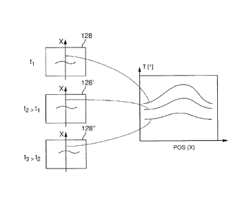
three image details 128, 128' and 128" associated with
the same surface detail and recorded at different
points in time tl, t2>t1 and t3>t2 are shown on the left
11
I
1
CA 02794119 2016-11-30
- 29 -
in Figure 3B, a temperature profile that extends over
the defect in the x direction being determined in each
of the image details. In the part of the figure on the
right, the temperature profiles recorded one after the
other in time are presented together, the x axis
indicating the position POS (x) in the x direction and
the y axis indicating the temperature T. In this way it
is possible to determine the spatial-temporal heat
propagation in the region of a potential defect highly
accurately on a moving test object.
Each of the temperature profiles represents a region
extending transversely in relation to the defect, in
which the defect lies approximately in the middle. Each
of the temperature profiles has a local temperature
maximum, the level of which with respect to the
surrounding area decreases as time passes (quantified
for example by the temperature difference AT), whereas
the width of the maximum, given for example by the full
width at half maximum, in the location domain increases
as time passes. These positionally correctly assigned
local temperature profiles, recorded one after the
other in time, then allow quantitative conclusions to
be drawn with respect to the spatial-temporal heat
propagation in the region of a potential defect and can
be evaluated as follows.
Figure 4 shows respectively in 4A and 4B
representations of a large number of positionally
correctly assigned temperature profiles together, the
temperature profiles that are respectively shown at the
top in the representations having been recorded at
earlier times than the temperature profiles
respectively shown below them. Figure 4A shows typical
temperature profiles for a disturbance ST, which though
it produces a local temperature maximum at
approximately pixel no. 7, is not attributable to a
1,
h
CA 02794119 2016-11-30
- 30 -
crack near the surface. Figure 4B shows for comparison
the positionally correctly assigned temperature
profiles from the region of a crack-like defect DEF,
here too the local temperature maximum respectively
lying in the region of pixel no. 7. The positionally
correctly assigned temperature profiles are then
analyzed on the basis of evaluation criteria, which on
account of the spatial-temporal development of the
temperature profiles allow relatively reliable
conclusions to be drawn as to whether the spatial-
temporal development of the temperature distribution
corresponds to the expected dynamic behavior, caused by
the heat flow, in the region of a crack or other
microstructural disturbance, or conforms to other laws.
One of the evaluation criteria or characteristic
variables is the amplitude AMPM of the temperature
value at the location of the local temperature maximum
within a temperature profile. Another characteristic
variable that has proven to be very reliable for
assessing the dynamic behavior of the heat propagation
is the heat concentration value KONZ in the region of a
local maximum of the temperature values within the
temperature profiles. Figure 5 shows in 5A the
variation over time of the amplitude AMPM and of the
concentration value KONZ at various time increments t
for a disturbance ST not attributable to a crack and in
Figure 5B the variation over time of the same
characteristic variables in the same time window for a
crack DEF near the surface. The temperature difference
AT of the temperature at the location of the local
maximum with respect to the surrounding area is
respectively indicated on the y axes.
It has been found in a large number of tests that, in
the region of cracks, both the cooling-down rate, or
the change over time in the temperature at the location
1
h
CA 02794119 2016-11-30
- 31 -
of the local temperature maximum, and the loss in
concentration are relatively great and differ
significantly from the corresponding values that can be
demonstrated in the region of disturbances that are not
attributable to cracks or other microstructural
disturbances. With the temperature maximum, which is
represented by the amplitude AMPM, the temperature at
the location of the local maximum, it has been found
that it decreases continuously after completion of the
heating-up phase, i.e. during the cooling-down process,
and does so with a relatively high cooling-down rate.
In the case of the example, a high probability of the
presence of a crack is assumed if the cooling-down rate
in the region of at least five thermographic images
recorded one after the other is greater than a
predetermined threshold value for the cooling-down
rate. The heat volume concentration value KONZ is a
measure of the ratio of the volume of heat directly at
the local temperature maximum in comparison with the
nearby surrounding area. If the heat concentration
value falls over time, this is an indication that heat
is, inter alia, flowing away laterally into the
surrounding area. This is the case for example with
cracks and is accordingly considered to be a sign that
the observed signal was caused by the heat propagation
in the solid body in the vicinity of a crack.
In the case of the example of a disturbance not
attributable to a crack that is explained on the basis
of Figure 5A, on the other hand, the heat volume
concentration KONZ is lower from the outset than in the
case of a crack; furthermore, the heat volume
concentration value initially increases at the
beginning of the observed time interval, before it
gradually falls. The maximum amplitude AMPM also
initially increases, before it falls with a relatively
low cooling-down rate, which is distinctly less than
11
h
CA 02794119 2016-11-30
- 32 -
the cooling-down rate expected in the region of a crack
(Figure 5B).
Other deviations of the spatial-temporal behavior of
the heat volume concentration from the typical behavior
caused by heat flow in the case of defects may also
occur and be used as an indication of a disturbance
that is not attributable to a crack or the like. For
example, the heat volume concentration value may remain
largely constant over a relatively long time or appear
to increase or decrease disproportionately.
These examples show that the analysis and quantitative
evaluation of spatial-temporal developments of
temperature profiles make it possible to distinguish
reliably between different causes of local temperature
maxima first found in a temperature profile. If, in the
case of an anomaly that is first found, the
characteristics described in conjunction with Figures
4B and 5B are in principle established, the cause is
classified as a crack and, if appropriate, the
corresponding surface portion is marked by the marking
device 170. If, on the other hand, the spatial-temporal
analysis shows a behavior that is untypical of cracks,
voids and other microstructural disturbances (cf., for
example, Figures 4A and 5A), a crack is not indicated.
In this way, pseudo-indications can be avoided with a
high degree of reliability. The inclusion of the
spatial-temporal heat propagation in the region of a
potential defect contributes decisively to the
interference suppression in the detection and
identification of defects with the aid of thermographic
signals.
On the basis of Figure 6, it is explained once again by
way of example in what way the analysis of the spatial-
temporal heat distribution can contribute to
1,
H
CA 02794119 2016-11-30
- 33 -
interference suppression. For this purpose, Figure 6A
shows the detail of a temperature profile which, for
instance in the region of pixel 455, contains a very
pronounced local temperature maximum with a temperature
difference AT of at least 10 K with respect to the
surrounding area. In the case of some conventional
testing systems, such indications would be
automatically considered to be a sure sign of the
presence of a deep crack and the test object would be
correspondingly marked and possibly discarded. The
spatial-temporal analysis of the heat propagation,
however, shows that a crack is not concerned. In Figure
6B, positionally correctly assigned temperature
profiles from the region of the local maximum for
different points in time are shown. A special feature
in comparison with the profiles from Figure 4 is that
the profile with the greatest amplitude was recorded at
a later time (t2 > t1) than the profile with a
distinctly smaller amplitude that was recorded at the
earlier point in time tl. The anomaly can also be seen
from the variations over time, shown in Figure 60, of
the characteristic variables of the amplitude of the
local maximum (AMPM) and the heat volume concentration
value (KONZ). Both values increase with time, which
cannot be explained by heat propagation in the region
of a locally heated-up crack. In the case of the
example, the strong local temperature maximum shown in
Figure 6A is attributable to a reflection at the
corresponding location of the surface of the test
piece. Since the development over time of the
temperature profiles does not show in any respect a
propagation behavior that is typical of cracks, such a
reflection would therefore not lead to a classification
as a crack. On the other hand, it is highly probable
that the reflection would be wrongly interpreted as a
crack by conventional systems.
I
'
I
I
CA 02794119 2016-11-30
- 34 -
,
Alternatively or in addition to the characteristic
variables explained here by way of example, other
characteristic variables may also be used as the
evaluation criterion. For example, derivatives of the
time functions described, for example the changing of
the cooling-down rate over time, may be used for this
purpose. Since the heat propagation can in essence be
described by solutions of the heat diffusion equation,
it is also possible to quantify the development over
time of the temperature profiles in the region of a
local maximum by fitting a Gaussian curve or an error
function, a good fit in these cases allowing the
assumption that there is a heat propagation dominated
by heat flow, while a poor fit suggests other causes.
It is also possible to fit polynomials as approximation
functions to the temperature profiles and to draw a
distinction between the defects sought (for example
cracks) and uncritical interferences (for example
reflections) by the analysis of polynomial
coefficients.
II