Note: Descriptions are shown in the official language in which they were submitted.
- CA 02794402 2014-01-22
74769-3471
= 1
METHODS AND APPARATUSES FOR RADIO RESOURCE MANAGEMENT
MEASUREMENTS OF A USER EQUIPMENT IN A HETEROGENEOUS.
.
. NETWORK =
CROSS-REFERENCE TO RELATED APPLICATIONS
[0001] This application claims benefit of U.S. Provisional
Patent Application Serial
No. 61/323,858, filed April 13, 2010 .
BACKGROUND
I. Field
[0002] The present disclosure relates generally to
communication, and more
= specifically to techniques for supporting communication in a wireless
communication
network.
II. Background
[0003] Wireless communication networks are widely deployed
to provide various
= communication services such as voice, video, packet data, messaging,
broadcast, etc.
These wireless networks may be multiple-access networks capable of supporting
multiple users by sharing the available network resources. Examples of such
multiple-
access networks include Code Division Multiple Access (CDMA) networks, Time
Division Multiple Access (TDMA) networks, Frequency Division Multiple Access
(FDMA) networks, Orthogonal FDMA (OFDMA) networks, and Single-Carrier FDMA
(SC-FDMA) networks.
[0004] A wireless communication network may include a number
of base stations
that can support communication for a number of user equipments (UEs). A HE may
communicate with a base station via the downlink and uplink. The downlink (or
forward link) refers to the communication link from the base station to the
UE, and the
= uplink (or reverse link) refers to the communication link from the UE to
the base station.
[0005] A base station may transmit data and control
information on the downlink to
a HE and/or may receive data and control information on the uplink from the
HE. On
the downlink, a transmission from the base station may observe interference
due to
transmissions from neighbor base stations. On the uplink, a transmission from
the HE
may cause interference to transmissions from other UEs communicating with the
= =
. -
CA 02794402 2014-08-28
74769-3471
2
neighbor base stations. The interface may degrade performance on both the
downlink and
uplink.
SUMMARY
[0006] Certain aspects of the present disclosure generally relate to
performing radio
resource management (RRM) measurements in a heterogeneous network (HetNet) in
an effort
to prevent failure of RRM measurement procedures with one cell in the presence
of severe
interference from another cell. Several alternatives are provided for
determining particular
resources (e.g., subframes) to use for performing the RRM measurements,
wherein the
particular resources are based on cooperative resource partitioning between
cells of the
HetNet, wherein the cells may be of different types (e.g., macro, pico, or
femto cells). These
alternatives include, for example: (1) intra-frequency or intra-RAT (radio
access technology)
alternatives, which may involve transmitting resource partitioning information
(RPI) or
deriving non-serving cell RPI based on the serving cell's RPI, as well as (2)
inter-frequency or
inter-RAT alternatives, where the RRM measurements may be performed during a
measurement gap. In this manner, the UE may make radio resource measurements
of signals
received from one cell during certain subframes with limited interference from
another cell.
[0007] Certain aspects of the present disclosure provide a method for
wireless
communications, comprising: receiving transmissions from a plurality of cells,
the
transmissions including a plurality of subframes; determining a set of
subframes, from the
plurality of subframes, to include in a radio resource measurement based on
resource
partitioning information (RPI); and performing the radio resource measurement
of the
determined set of subframes.
[0008] Certain aspects of the present disclosure provide an apparatus
for wireless
communications, comprising: means for receiving transmissions from a plurality
of cells, the
transmissions including a plurality of subframes; means for determining a set
of subframes,
from the plurality of subframes, to include in a radio resource measurement
based on resource
partitioning information (RPI); and means for performing the radio resource
measurement of
the determined set of subframes.
CA 02794402 2014-08-28
74769-3471
3
[0009] Certain aspects of the present disclosure provide an apparatus
for wireless
communications, comprising: a receiver configured to receive transmissions
from a plurality
of cells, the transmissions including a plurality of subframes; and at least
one processor
configured to: determine a set of subframes, from the plurality of subframes,
to include in a
radio resource measurement based on resource partitioning information (RPI);
and perform
the radio resource measurement of the determined set of subframes.
[0010] Certain aspects of the present disclosure provide a computer
program product
for wireless communications, comprising: a computer-readable medium having
computer
executable code stored thereon that when executed causes the computer to:
receive
transmissions from a plurality of cells, the transmissions including a
plurality of subframes;
determine a set of subframes, from the plurality of subframes, to include in a
radio resource
measurement based on resource partitioning information (RPI); and perform the
radio
resource measurement of the determined set of subframes.
[0011] Certain aspects of the present disclosure provide a method for
wireless
communications. The method generally includes determining, at a first base
station, a
measurement gap associated with a second base station for an inter-frequency
or an inter-RAT
(radio access technology) radio resource measurement; generating, at the first
base station,
resource partitioning information (RPI) with at least one subframe designated
for radio
resource measurements of the first base station; and transmitting subframes
from the first base
station according to the RPI, wherein the at least one subframe designated for
radio resource
measurements of the first base station falls within the measurement gap
associated with the
second base station.
[0012] Certain aspects of the present disclosure provide an apparatus
for wireless
communications. The apparatus generally includes means for determining a
measurement gap
associated with a base station for an inter-frequency or an inter-RAT (radio
access
technology) radio resource measurement; means for generating resource
partitioning
information (RPI) with at least one subframe designated for radio resource
measurements of
the apparatus; and means for transmitting subframes from the apparatus
according to the RPI,
CA 02794402 2014-08-28
74769-3471
3a
wherein the at least one subframe designated for radio resource measurements
of the
apparatus falls within the measurement gap associated with the base station.
[0013] Certain aspects of the present disclosure provide an apparatus
for wireless
communications. The apparatus generally includes at least one processor and a
transmitter.
The at least one processor is typically configured to determine a measurement
gap associated
with a base station for an inter-frequency or an inter-RAT (radio access
technology) radio
resource measurement and to generate, resource partitioning information (RPI)
with at least
one subframe designated for radio resource measurements of the first base
station. The
transmitter is generally configured to
CA 02794402 2012-09-24
WO 2011/130452 PCT/US2011/032375
4
transmit subframes from the apparatus according to the RPI, wherein the at
least one
subframe designated for radio resource measurements of the apparatus falls
within the
measurement gap associated with the base station.
[0014] Certain aspects of the present disclosure provide a computer-program
product for wireless communications. The computer-program product typically
includes a computer-readable medium having code for determining, at a first
base
station, a measurement gap associated with a second base station for an inter-
frequency
or an inter-RAT (radio access technology) radio resource measurement; for
generating,
at the first base station, resource partitioning information (RPI) with at
least one
subframe designated for radio resource measurements of the first base station;
and for
transmitting subframes from the first base station according to the RPI,
wherein the at
least one subframe designated for radio resource measurements of the first
base station
falls within the measurement gap associated with the second base station.
[0015] Various aspects and features of the disclosure are described in
further detail
below.
BRIEF DESCRIPTION OF THE DRAWINGS
[0016] FIG. 1 is a block diagram conceptually illustrating an example of a
wireless
communications network in accordance with certain aspects of the present
disclosure.
[0017] FIG. 2 is a block diagram conceptually illustrating an example of a
frame
structure in a wireless communications network in accordance with certain
aspects of
the present disclosure.
[0018] FIG. 2A shows an example format for the uplink in Long Term
Evolution
(LTE) in accordance with certain aspects of the present disclosure.
[0019] FIG. 3 is a block diagram conceptually illustrating an example of a
Node B
in communication with a user equipment (UE) in a wireless communications
network in
accordance with certain aspects of the present disclosure.
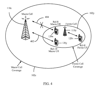
[0020] FIG. 4 illustrates an example heterogeneous network in accordance
with
certain aspects of the present disclosure.
[0021] FIG. 5 illustrates example resource partitioning in a heterogeneous
network
in accordance with certain aspects of the present disclosure.
[0022] FIG. 6 illustrates example cooperative partitioning of subframes in
a
heterogeneous network in accordance with certain aspects of the present
disclosure.
CA 02794402 2012-09-24
WO 2011/130452 PCT/US2011/032375
[0023] FIG. 7 illustrates example cooperative partitioning of subframes
with three
use (U) subframes and various measurement gaps for making inter-frequency or
inter-
RAT (radio access technology) measurements, in accordance with certain aspects
of the
present disclosure.
[0024] FIG. 8 is a functional block diagram conceptually illustrating
example
blocks executed to perform radio resource measurement for determined
subframes, in
accordance with certain aspects of the present disclosure.
[0025] FIG. 8A illustrates example components capable of performing the
operations
illustrated in FIG. 8.
[0026] FIG. 9 is a functional block diagram conceptually illustrating
example
blocks executed to generate resource partitioning information (RPI) at a first
base
station such that at least one subframe designated for radio resource
measurement falls
within a measurement gap associated with the second base station, in
accordance with
certain aspects of the present disclosure.
[0027] FIG. 9A illustrates example components capable of performing the
operations
illustrated in FIG. 9.
DETAILED DESCRIPTION
[0028] The techniques described herein may be used for various wireless
communication networks such as CDMA, TDMA, FDMA, OFDMA, SC-FDMA and
other networks. The terms "network" and "system" are often used
interchangeably. A
CDMA network may implement a radio technology such as Universal Terrestrial
Radio
Access (UTRA), cdma2000, etc. UTRA includes Wideband CDMA (WCDMA) and
other variants of CDMA. cdma2000 covers IS-2000, IS-95 and IS-856 standards. A
TDMA network may implement a radio technology such as Global System for Mobile
Communications (GSM). An OFDMA network may implement a radio technology
such as Evolved UTRA (E-UTRA), Ultra Mobile Broadband (UMB), IEEE 802.11 (Wi-
Fi), IEEE 802.16 (WiMAX), IEEE 802.20, Flash-OFDM , etc. UTRA and E-UTRA
are part of Universal Mobile Telecommunication System (UMTS). 3GPP Long Term
Evolution (LTE) and LTE-Advanced (LTE-A) are new releases of UMTS that use E-
UTRA. UTRA, E-UTRA, UMTS, LTE, LTE-A and GSM are described in documents
from an organization named "3rd Generation Partnership Project" (3GPP).
cdma2000
and UMB are described in documents from an organization named "3rd Generation
CA 02794402 2012-09-24
WO 2011/130452 PCT/US2011/032375
6
Partnership Project 2" (3GPP2). The techniques described herein may be used
for the
wireless networks and radio technologies mentioned above as well as other
wireless
networks and radio technologies. For clarity, certain aspects of the
techniques are
described below for LTE, and LTE terminology is used in much of the
description
below.
Example Wireless Network
[0029] FIG. 1 shows a wireless communication network 100, which may be an
LTE
network. The wireless network 100 may include a number of evolved Node Bs
(eNBs)
110 and other network entities. An eNB may be a station that communicates with
user
equipment devices (UEs) and may also be referred to as a base station, a Node
B, an
access point, etc. Each eNB 110 may provide communication coverage for a
particular
geographic area. In 3GPP, the term "cell" can refer to a coverage area of an
eNB and/or
an eNB subsystem serving this coverage area, depending on the context in which
the
term is used.
[0030] An eNB may provide communication coverage for a macro cell, a pico
cell,
a femto cell, and/or other types of cell. A macro cell may cover a relatively
large
geographic area (e.g., several kilometers in radius) and may allow
unrestricted access by
UEs with service subscription. A pico cell may cover a relatively small
geographic area
and may allow unrestricted access by UEs with service subscription. A femto
cell may
cover a relatively small geographic area (e.g., a home) and may allow
restricted access
by UEs having association with the femto cell (e.g., UEs in a Closed
Subscriber Group
(CSG), UEs for users in the home, etc.). An eNB for a macro cell may be
referred to as
a macro eNB. An eNB for a pico cell may be referred to as a pico eNB. An eNB
for a
femto cell may be referred to as a femto eNB or a home eNB. In the example
shown in
FIG. 1, eNBs 110a, 110b and 110c may be macro eNBs for macro cells 102a, 102b
and
102c, respectively. eNB 110x may be a pico eNB for a pico cell 102x. eNBs 110y
and
110z may be femto eNBs for femto cells 102y and 102z, respectively. An eNB may
support one or multiple (e.g., three) cells.
[0031] The wireless network 100 may also include relay stations. A relay
station is
a station that receives a transmission of data and/or other information from
an upstream
station (e.g., an eNB or a UE) and sends a transmission of the data and/or
other
information to a downstream station (e.g., a UE or an eNB). A relay station
may also be
a UE that relays transmissions for other UEs. In the example shown in FIG. 1,
a relay
station 110r may communicate with eNB 110a and a UE 120r in order to
facilitate
CA 02794402 2012-09-24
WO 2011/130452 PCT/US2011/032375
7
communication between eNB 110a and UE 120r. A relay station may also be
referred
to as a relay eNB, a relay, etc.
[0032] The wireless network 100 may be a heterogeneous network (HetNet)
that
includes eNBs of different types, e.g., macro eNBs, pico eNBs, femto eNBs,
relays, etc.
These different types of eNBs may have different transmit power levels,
different
coverage areas, and different impact on interference in the wireless network
100. For
example, macro eNBs may have a high transmit power level (e.g., 20 watts)
whereas
pico eNBs, femto eNBs and relays may have a lower transmit power level (e.g.,
1 watt).
[0033] The wireless network 100 may support synchronous or asynchronous
operation. For synchronous operation, the eNBs may have similar frame timing,
and
transmissions from different eNBs may be approximately aligned in time. For
asynchronous operation, the eNBs may have different frame timing, and
transmissions
from different eNBs may not be aligned in time. The techniques described
herein may
be used for both synchronous and asynchronous operation.
[0034] A network controller 130 may couple to a set of eNBs and provide
coordination and control for these eNBs. The network controller 130 may
communicate
with the eNBs 110 via a backhaul. The eNBs 110 may also communicate with one
another, e.g., directly or indirectly via wireless or wireline backhaul.
[0035] The UEs 120 may be dispersed throughout the wireless network 100,
and
each UE may be stationary or mobile. A UE may also be referred to as a
terminal, a
mobile station, a subscriber unit, a station, etc. A UE may be a cellular
phone, a
personal digital assistant (PDA), a wireless modem, a wireless communication
device, a
handheld device, a laptop computer, a cordless phone, a wireless local loop
(WLL)
station, a tablet, etc. A UE may be able to communicate with macro eNBs, pico
eNBs,
femto eNBs, relays, etc. In FIG. 1, a solid line with double arrows indicates
desired
transmissions between a UE and a serving eNB, which is an eNB designated to
serve
the UE on the downlink and/or uplink. A dashed line with double arrows
indicates
interfering transmissions between a UE and an eNB.
[0036] LTE utilizes orthogonal frequency division multiplexing (OFDM) on
the
downlink and single-carrier frequency division multiplexing (SC-FDM) on the
uplink.
OFDM and SC-FDM partition the system bandwidth into multiple (K) orthogonal
subcarriers, which are also commonly referred to as tones, bins, etc. Each
subcarrier
may be modulated with data. In general, modulation symbols are sent in the
frequency
domain with OFDM and in the time domain with SC-FDM. The spacing between
CA 02794402 2012-09-24
WO 2011/130452 PCT/US2011/032375
8
adjacent subcarriers may be fixed, and the total number of subcarriers (K) may
be
dependent on the system bandwidth. For example, K may be equal to 128, 256,
512,
1024 or 2048 for system bandwidth of 1.25, 2.5, 5, 10, or 20 megahertz (MHz),
respectively. The system bandwidth may also be partitioned into subbands. For
example, a subband may cover 1.08 MHz, and there may be 1, 2, 4, 8, or 16
subbands
for system bandwidth of 1.25, 2.5, 5, 10, or 20 MHz, respectively.
[0037] FIG. 2 shows a frame structure used in LTE. The transmission
timeline for
the downlink may be partitioned into units of radio frames. Each radio frame
may have
a predetermined duration (e.g., 10 milliseconds (ms)) and may be partitioned
into 10
subframes with indices of 0 through 9. Each subframe may include two slots.
Each
radio frame may thus include 20 slots with indices of 0 through 19. Each slot
may
include L symbol periods, e.g., L = 7 symbol periods for a normal cyclic
prefix (as
shown in FIG. 2) or L = 6 symbol periods for an extended cyclic prefix. The 2L
symbol periods in each subframe may be assigned indices of 0 through 2L-1. The
available time frequency resources may be partitioned into resource blocks.
Each
resource block may cover N subcarriers (e.g., 12 subcarriers) in one slot.
[0038] In LTE, an eNB may send a primary synchronization signal (PSS) and a
secondary synchronization signal (SSS) for each cell in the eNB. The primary
and
secondary synchronization signals may be sent in symbol periods 6 and 5,
respectively,
in each of subframes 0 and 5 of each radio frame with the normal cyclic
prefix, as
shown in FIG. 2. The synchronization signals may be used by UEs for cell
detection
and acquisition. The eNB may send a Physical Broadcast Channel (PBCH) in
symbol
periods 0 to 3 in slot 1 of subframe 0. The PBCH may carry certain system
information.
[0039] The eNB may send a Physical Control Format Indicator Channel
(PCFICH)
in the first symbol period of each subframe, as shown in FIG. 2. The PCFICH
may
convey the number of symbol periods (M) used for control channels, where M may
be
equal to 1, 2, or 3 and may change from subframe to subframe. M may also be
equal to
4 for a small system bandwidth, e.g., with less than 10 resource blocks. The
eNB may
send a Physical HARQ Indicator Channel (PHICH) and a Physical Downlink Control
Channel (PDCCH) in the first M symbol periods of each subframe (not shown in
FIG.
2). The PHICH may carry information to support hybrid automatic repeat request
(HARQ). The PDCCH may carry information on resource allocation for UEs and
control information for downlink channels. The eNB may send a Physical
Downlink
Shared Channel (PDSCH) in the remaining symbol periods of each subframe. The
CA 02794402 2012-09-24
WO 2011/130452 PCT/US2011/032375
9
PDSCH may carry data for UEs scheduled for data transmission on the downlink.
The
various signals and channels in LTE are described in 3GPP TS 36.211, entitled
"Evolved Universal Terrestrial Radio Access (E-UTRA); Physical Channels and
Modulation," which is publicly available.
[0040] The eNB may send the PSS, SSS, and PBCH in the center 1.08 MHz of
the
system bandwidth used by the eNB. The eNB may send the PCFICH and PHICH
across the entire system bandwidth in each symbol period in which these
channels are
sent. The eNB may send the PDCCH to groups of UEs in certain portions of the
system
bandwidth. The eNB may send the PDSCH to specific UEs in specific portions of
the
system bandwidth. The eNB may send the PSS, SSS, PBCH, PCFICH, and PHICH in a
broadcast manner to all UEs, may send the PDCCH in a unicast manner to
specific UEs,
and may also send the PDSCH in a unicast manner to specific UEs.
[0041] A number of resource elements may be available in each symbol
period.
Each resource element may cover one subcarrier in one symbol period and may be
used
to send one modulation symbol, which may be a real or complex value. Resource
elements not used for a reference signal in each symbol period may be arranged
into
resource element groups (REGs). Each REG may include four resource elements in
one
symbol period. The PCFICH may occupy four REGs, which may be spaced
approximately equally across frequency, in symbol period 0. The PHICH may
occupy
three REGs, which may be spread across frequency, in one or more configurable
symbol periods. For example, the three REGs for the PHICH may all belong in
symbol
period 0 or may be spread in symbol periods 0, 1, and 2. The PDCCH may occupy
9,
18, 32, or 64 REGs, which may be selected from the available REGs, in the
first M
symbol periods. Only certain combinations of REGs may be allowed for the
PDCCH.
[0042] A UE may know the specific REGs used for the PHICH and the PCFICH.
The UE may search different combinations of REGs for the PDCCH. The number of
combinations to search is typically less than the number of allowed
combinations for the
PDCCH. An eNB may send the PDCCH to the UE in any of the combinations that the
UE will search.
[0043] FIG. 2A shows an exemplary format 200A for the uplink in LTE. The
available resource blocks for the uplink may be partitioned into a data
section and a
control section. The control section may be formed at the two edges of the
system
bandwidth and may have a configurable size. The resource blocks in the control
section
may be assigned to UEs for transmission of control information. The data
section may
CA 02794402 2012-09-24
WO 2011/130452 PCT/US2011/032375
include all resource blocks not included in the control section. The design in
FIG. 2A
results in the data section including contiguous subcarriers, which may allow
a single
UE to be assigned all of the contiguous subcarriers in the data section.
[0044] A UE may be assigned resource blocks in the control section to
transmit
control information to an eNB. The UE may also be assigned resource blocks in
the
data section to transmit data to the eNB. The UE may transmit control
information in a
Physical Uplink Control Channel (PUCCH) 210 on the assigned resource blocks in
the
control section. The UE may transmit only data or both data and control
information in
a Physical Uplink Shared Channel (PUSCH) 220 on the assigned resource blocks
in the
data section. An uplink transmission may span both slots of a subframe and may
hop
across frequency as shown in FIG. 2A.
[0045] A UE may be within the coverage of multiple eNBs. One of these eNBs
may be selected to serve the UE. The serving eNB may be selected based on
various
criteria such as received power, pathloss, signal-to-noise ratio (SNR), etc.
[0046] A UE may operate in a dominant interference scenario in which the UE
may
observe high interference from one or more interfering eNBs. A dominant
interference
scenario may occur due to restricted association. For example, in FIG. 1, UE
120y may
be close to femto eNB 110y and may have high received power for eNB 110y.
However, UE 120y may not be able to access femto eNB 110y due to restricted
association and may then connect to macro eNB 110c with lower received power
(as
shown in FIG. 1) or to femto eNB 110z also with lower received power (not
shown in
FIG. 1). UE 120y may then observe high interference from femto eNB 110y on the
downlink and may also cause high interference to eNB 110y on the uplink.
[0047] A dominant interference scenario may also occur due to range
extension,
which is a scenario in which a UE connects to an eNB with lower pathloss and
lower
SNR among all eNBs detected by the UE. For example, in FIG. 1, UE 120x may
detect
macro eNB 110b and pico eNB 110x and may have lower received power for eNB
110x
than eNB 110b. Nevertheless, it may be desirable for UE 120x to connect to
pico eNB
110x if the pathloss for eNB 110x is lower than the pathloss for macro eNB
110b. This
may result in less interference to the wireless network for a given data rate
for UE 120x.
[0048] In an aspect, communication in a dominant interference scenario may
be
supported by having different eNBs operate on different frequency bands. A
frequency
band is a range of frequencies that may be used for communication and may be
given by
(i) a center frequency and a bandwidth or (ii) a lower frequency and an upper
frequency.
CA 02794402 2012-09-24
WO 2011/130452 PCT/US2011/032375
11
A frequency band may also be referred to as a band, a frequency channel, etc.
The
frequency bands for different eNBs may be selected such that a UE can
communicate
with a weaker eNB in a dominant interference scenario while allowing a strong
eNB to
communicate with its UEs. An eNB may be classified as a "weak" eNB or a
"strong"
eNB based on the received power of signals from the eNB received at a UE (and
not
based on the transmit power level of the eNB).
[0049] FIG. 3 is a block diagram of a design of a base station or an eNB
110 and a
UE 120, which may be one of the base stations/eNBs and one of the UEs in FIG.
1. For
a restricted association scenario, the eNB 110 may be macro eNB 110c in FIG.
1, and
the UE 120 may be UE 120y. The eNB 110 may also be a base station of some
other
type. The eNB 110 may be equipped with T antennas 334a through 334t, and the
UE
120 may be equipped with R antennas 352a through 352r, where in general T 1
and
R > 1 .
[0050] At the eNB 110, a transmit processor 320 may receive data from a
data
source 312 and control information from a controller/processor 340. The
control
information may be for the PBCH, PCFICH, PHICH, PDCCH, etc. The data may be
for
the PDSCH, etc. The transmit processor 320 may process (e.g., encode and
symbol
map) the data and control information to obtain data symbols and control
symbols,
respectively. The transmit processor 320 may also generate reference symbols,
e.g., for
the PSS, SSS, and cell-specific reference signal. A transmit (TX) multiple-
input
multiple-output (MIMO) processor 330 may perform spatial processing (e.g.,
precoding) on the data symbols, the control symbols, and/or the reference
symbols, if
applicable, and may provide T output symbol streams to T modulators (MODs)
332a
through 332t. Each modulator 332 may process a respective output symbol stream
(e.g.,
for OFDM, etc.) to obtain an output sample stream. Each modulator 332 may
further
process (e.g., convert to analog, amplify, filter, and upconvert) the output
sample stream
to obtain a downlink signal. T downlink signals from the modulators 332a
through 332t
may be transmitted via T antennas 334a through 334t, respectively.
[0051] At the UE 120, antennas 352a through 352r may receive the downlink
signals from the eNB 110 and may provide received signals to demodulators
(DEMODs) 354a through 354r, respectively. Each demodulator 354 may condition
(e.g., filter, amplify, downconvert, and digitize) a respective received
signal to obtain
input samples. Each demodulator 354 may further process the input samples
(e.g., for
OFDM, etc.) to obtain received symbols. A MIMO detector 356 may obtain
received
CA 02794402 2012-09-24
WO 2011/130452 PCT/US2011/032375
12
symbols from all R demodulators 354a through 354r, perform MIMO detection on
the
received symbols, if applicable, and provide detected symbols. A receive
processor 358
may process (e.g., demodulate, deinterleave, and decode) the detected symbols,
provide
decoded data for the UE 120 to a data sink 360, and provide decoded control
information to a controller/processor 380.
[0052] On the uplink, at the UE 120, a transmit processor 364 may receive
and
process data (e.g., for the PUSCH) from a data source 362 and control
information (e.g.,
for the PUCCH) from the controller/processor 380. The transmit processor 364
may
also generate reference symbols for a reference signal. The symbols from the
transmit
processor 364 may be precoded by a TX MIMO processor 366 if applicable,
further
processed by modulators 354a through 354r (e.g., for SC-FDM, etc.), and
transmitted to
the eNB 110. At the eNB 110, the uplink signals from the UE 120 may be
received by
the antennas 334, processed by demodulators 332, detected by a MIMO detector
336 if
applicable, and further processed by a receive processor 338 to obtain decoded
data and
control information sent by the UE 120. The receive processor 338 may provide
the
decoded data to a data sink 339 and the decoded control information to the
controller/processor 340.
[0053] The controllers/processors 340 and 380 may direct the operation at
the eNB
110 and the UE 120, respectively. The controller/processor 380 and/or other
processors
and modules at the UE 120 may perform or direct operations for blocks 800 in
FIG. 8
and/or other processes for the techniques described herein. The
controller/processor
340 and/or other processors and modules at the eNB 110 may perform or direct
operations for blocks 900 in FIG. 9 and/or other processes for the techniques
described
herein. The memories 342, 382 may store data and program codes for the eNB 110
and
the UE 120, respectively. A scheduler 344 may schedule UEs for data
transmission on
the downlink and/or uplink.
Example Resource Partitioning
[0054] According to certain aspects of the present disclosure, when a
network
supports enhanced inter-cell interference coordination (eICIC), the base
stations may
negotiate with each other to coordinate resources in order to reduce/eliminate
interference by the interfering cell giving up part of its resources. In
accordance with
this interference coordination, a UE may be able to access a serving cell even
with
severe interference by using resources yielded by the interfering cell.
CA 02794402 2012-09-24
WO 2011/130452 PCT/US2011/032375
13
[0055] For example, a femto cell with a closed access mode (i.e., in which
only a
member femto UE can access the cell) in the coverage area of an open macro
cell may
be able to create a "coverage hole" for the macro cell. By negotiating for the
femto cell
to yield some of its resources, effectively removing interference, the macro
UE under
the femto cell coverage area may still be able to access the UE's serving
macro cell
using these yielded resources.
[0056] In a radio access system using OFDM, such as Evolved Universal
Terrestrial
Radio Access Network (E-UTRAN), the yielded resources may be time based,
frequency based, or a combination of both. When the coordinated resource
partitioning
is time based, the interfering cell may simply not use some of the subframes
in the time
domain. When the yielded resources (i.e., the coordinated resource
partitioning) are
frequency based, the interfering cell may yield subcarriers in the frequency
domain.
When the coordinated resource partitioning is a combination of both frequency
and
time, the interfering cell may yield certain frequency and time resources.
[0057] FIG. 4 illustrates an example scenario where eICIC may allow a macro
UE
120y supporting eICIC (e.g., a Rel-10 macro UE as shown in FIG. 4) to access
the
macro cell 110c even when the macro UE 120y is experiencing severe
interference from
the femto cell 110y, as illustrated by the solid radio link 402. A legacy
macro UE 120u
(e.g., a Re1-8 macro UE as shown in FIG. 4) may not be able to access the
macro cell
110c under severe interference from the femto cell 110y, as illustrated by the
broken
radio link 404. A femto UE 120v (e.g., a Re1-8 femto UE as shown in FIG. 4)
may
access the femto cell 110y without any interference problems from the macro
cell 110c.
[0058] According to certain aspects, networks may support eICIC, where
there may
be different sets of partitioning information. A first of these sets may be
referred to as
Semi-Static Resource Partitioning information (SRPI). A second of these sets
may be
referred to as Adaptive Resource Partitioning Information (ARPI). As the name
implies, SRPI typically does not change frequently, and SRPI may be sent to a
UE so
that the UE can use the resource partitioning information for the UE's own
operations.
[0059] As an example, the resource partitioning may be implemented with 8
ms
periodicity (8 subframes) or 40 ms periodicity (40 subframes). According to
certain
aspects, it may be assumed that frequency division duplexing (FDD) may also be
applied such that frequency resources may also be partitioned. For
communications via
the downlink (e.g., from a cell node B to a UE), a partitioning pattern may be
mapped to
a known subframe (e.g., a first subframe of each radio frame that has a system
frame
CA 02794402 2012-09-24
WO 2011/130452 PCT/US2011/032375
14
number (SFN) value that is a multiple of an integer N, such as 4). Such a
mapping may
be applied in order to determine resource partitioning information (RPI) for a
specific
subframe. As an example, a subframe that is subject to coordinated resource
partitioning (e.g., yielded by an interfering cell) for the downlink may be
identified by
an index:
IndexsRpi DL = (SFN * 10 + subframe number) mod 8
[0060] For the uplink, the SRPI mapping may be shifted, for example, by 4
ms.
Thus, an example for the uplink may be:
Indexsm uL = (SFN * 10 + subframe number + 4) mod 8
[0061] SRPI may use the following three values for each entry:
= U (Use): this value indicates the subframe has been cleaned up from the
dominant interference to be used by this cell (i.e., the main interfering
cells
do not use this subframe);
= N (No Use): this value indicates the subframe shall not be used; and
= X (Unknown): this value indicates the subframe is not statically
partitioned.
Details of resource usage negotiation between base stations are not known to
the UE.
[0062] Another possible set of parameters for SRPI may be the following:
= U (Use): this value indicates the subframe has been cleaned up from the
dominant interference to be used by this cell (i.e., the main interfering
cells
do not use this subframe);
= N (No Use): this value indicates the subframe shall not be used;
= X (Unknown): this value indicates the subframe is not statically
partitioned
(and details of resource usage negotiation between base stations are not
known to the UE); and
= C (Common): this value may indicate all cells may use this subframe
without resource partitioning. This subframe may be subject to interference,
so that the base station may choose to use this subframe only for a UE that is
not experiencing severe interference.
[0063] The serving cell's SRPI may be broadcasted over the air. In E-UTRAN,
the
SRPI of the serving cell may be sent in a master information block (MIB), or
one of the
system information blocks (SIBs). A predefined SRPI may be defined based on
the
characteristics of cells, e.g., macro cell, pico cell (with open access), and
femto cell
CA 02794402 2012-09-24
WO 2011/130452 PCT/US2011/032375
(with closed access). In such a case, encoding of SRPI in the system overhead
message
may result in more efficient broadcasting over the air.
[0064] The base station may also broadcast the neighbor cell's SRPI in one
of the
SIBs. For this, SRPI may be sent with its corresponding range of physical cell
identities
(PCIs).
[0065] ARPI may represent further resource partitioning information with
the
detailed information for the 'X' subframes in SRPI. As noted above, detailed
information for the 'X' subframes is typically known only to the base
stations, and a UE
does not know it.
[0066] FIGs. 5 and 6 illustrate examples of SRPI assignment as described
above in
the scenario with macro and femto cells.
Example HetNet UE RRM Measurements
[0067] A U subframe is a subframe that may be clean of dominant
interference. U
subframe information may be delivered to a UE. Radio resource management (RRM)
measurements may be made over only U subframes due to removed data
interference.
RRM measurements may comprise a reference signal received power (RSRP) and a
reference signal received quality (RSRQ). The RSRP may indicate received power
on a
cell-dedicated reference signal (CRS), and the RSRQ may indicate received
quality on
the CRS. The RSRQ may be calculated as follows:
RSRQ = N*RSRP/RSSI
where RSSI is the received signal strength indicator. The RSSI may
dramatically
change on different subframes, due to resource partitioning. The CRS may be
transmitted in all non-multimedia broadcast over a single frequency network
(MBSFN)
subframes; therefore, there may be no need to know the interlace. Interference
coordination of a colliding CRS may further improve the performance. The RSRQ
may
be redefined for an LTE Release 10 (Rel-10) UE:
RSRQ = N*RSRP / (RSSIu subframes ¨ RSRPorthogonalized interfering cell)
This may indicate the true performance of a U subframe.
[0068] RRM measurements from a serving/camping cell may be made since
resource partitioning information (RPI) may be made available from the serving
cell.
Therefore, which subframes to measure (i.e., U subframes) may be determined
based on
the RPI. RPI may not be known for a non-serving/camping cell. Certain aspects
of the
present disclosure disclose methods for determining which subframes to include
in a
radio resource measurement based on an RPI for the cells. Certain aspects
discussed
CA 02794402 2012-09-24
WO 2011/130452 PCT/US2011/032375
16
herein may apply to connected mode or idle mode, inter-frequency designs or
intra-
frequency designs, and serving cells or neighbor cells.
[0069] For certain aspects, a neighbor list from a serving cell may carry
the non-
serving cell RPI in a system information block (SIB). This aspect may apply in
a
macro-pico case, where the number of pico cells may be limited (i.e., physical
cell
identity (PCI)-to-RPI mapping). CSG cells (e.g., femto cells) may be allocated
one or
two patterns, but there may be no explicit PCI-to-RPI mapping. For certain
aspects, the
RPI may be the same for the same types of cells (e.g., macro, pico, or femto).
[0070] For certain aspects, a UE may derive a non-serving cell's RPI based
on a
serving cell's RPI. For certain aspects, the RPI of a serving cell and a non-
serving cell
may be the same, so the UE may consider the RPI for the non-serving cell to be
the
same as the RPI for the serving cell as part of deriving the non-serving
cell's RPI. In
other words, a UE may use the U subframe of the serving cell for non-serving
cell
measurements. For certain aspects, the RPI of the non-serving cell may
compliment the
RPI of the serving cell. In other words, a UE may use the N subframe of the
serving
cell for non-serving cell measurements (e.g., the non-serving cell may be a
different
class from the serving cell). For certain aspects, the UE may combine multiple
measurements over U and N subframes for final reporting (e.g., reporting
multiple
RSRQ and RSRP¨one from a U subframe and another from an N subframe). The best
RSRQ from these multiple measurements may be selected.
[0071] For certain aspects, a UE may perform blind detection based on
performing
RRM measurements over all subframes. The UE may be able to detect patterns by
determining which subframes the UE may be able to make good and bad
measurements
from, wherein the partitioning patterns may further allow the UE to determine
the
subframes (e.g., U subframes) to include in an RRM measurement.
[0072] For certain aspects, a UE may determine which subframes to measure
by
reading a system information block type 1 (SIB1) from an aggressor (e.g., a
neighbor
cell). This aspect may apply in a femto cell scenario, where a UE may read a
SIB1 of a
CSG to determine whether the UE may subscribe. A UE camped on a macro cell may
power up under a CSG, wherein the UE may read from the CSG SIB1 to determine
the
N subframe (i.e., the macro cell RPI assuming complimentary RPI from the femto
cell).
[0073] For certain aspects, the RPI for a non-serving cell may be carried
in a master
information block (MIB), which may allow a faster measurement procedure. For
CA 02794402 2012-09-24
WO 2011/130452 PCT/US2011/032375
17
certain aspects, four configurations may use 2 bits in the MIB, wherein the
RPI pattern
may be based on the type of cell.
[0074] For certain aspects, additional PCI partitioning for pico cells may
be
introduced, wherein the additional partitioning may be hard coded to PCI-to-
RPI spaces.
The PCI space partitioning may be broadcasted using a synchronization channel.
[0075] For inter-frequency or inter-radio access technology (RAT) design,
if cross-
layer synchronization and RPI is available, a neighbor list from a serving
cell may carry
the non-serving cell RPI, as in certain aspects described above. Used for
measuring
cells for inter-frequency or inter-RAT handover, the current measurement gap
(6 ms in
LTE), however, may not be compatible with interlace-based semi-static
partitioning
(i.e., RPI). The 6 ms gap with a 40 ms periodicity may permanently miss the U
interlace. The 6 ms gap may not capture the physical broadcast channel (PBCH);
therefore, there may be no system frame number (SFN) information. Cross
frequency
RPI may not be available or possible for asynchronous networks.
[0076] For certain aspects, the measurement gap may be increased by a
factor of
two to about 11 ms (contiguous) plus the MIB payload. For certain aspects, the
measurement gap lasts at least 10 ms. This may be sufficient to capture the
MIB in each
measurement gap. Further, at least one U interlace may be captured during each
measurement gap. For certain aspects, the RPI may be carried in the MIB.
[0077] For certain aspects, the measurement gap may be shifted, and there
may be
autonomous system information (SI) reading. First, the UE may measure the PCI
and
report to the serving cell. The serving cell may request the UE to perform an
autonomous SI reading (i.e., MIB or SIB). The UE may read the strongest cell
first,
then "bootstrap" the process to measure other cells. More specifically, a UE
may read
the MIB or SIB of the strongest cell(s) to find out the RPI of weaker cells.
Then the UE
acquires and measures the weak cells based on information (including the RPI)
acquired
from the strongest cell(s). In this manner, the UE may bootstrap, i.e, derive
or
determine a likely schedule for measuring the weaker cells, using the
information from
the strongest cell(s). Without using the information from the strongest
cell(s), the UE
would likely not be able to measure the weak cells straightaway. A UE may also
directly read the SIB of weak cells if sufficient information is provided in
the MIB. The
base station (e.g., an eNB) may decide whether to perform SI reading or not
based on
deployment knowledge (e.g., neighbor, band, UE subscription, location, etc).
The UE
may use a longer measurement gap for SI reading and generate SFN and RPI
CA 02794402 2012-09-24
WO 2011/130452 PCT/US2011/032375
18
information for all cells of interest. The UE may report this information and
request the
measurement gap to be shifted to coincide with the U subframe of some cells.
The base
station may configure the UE on shifted 6 ms gaps. For certain aspects,
multiple gaps
may be utilized to capture all cells since U subframes may be disjoint.
[0078] For certain aspects, the U subframes may be restricted to at least
two
interlaces per 8 ms resource partitioning period (e.g., at least one U
subframe every 4
ms, or at least two U subframes every 8 ms). This may ensure at least one good
measurement (i.e., a measurement with reduced/eliminated interference) in each
6 ms
measurement gap. The UE may select the best RSRQ to report. However, there may
be
a loss of granularity in this case.
[0079] For example, FIG. 7 illustrates example resource partitioning with
three U
subframes (i.e., greater than 2 U subframes) in every 8 ms SRPI period. In
this manner,
no matter where the measurement gap 702 occurs for making inter-frequency or
inter-
RAT measurements, there will be at least one good measurement (i.e., a
measurement
made in a U subframe without severe interference) in the measurement gap.
During a
measurement gap 702, communication with the serving cell is temporarily
suspended as
shown, such that a UE may measure other, non-serving cells for inter-frequency
or
inter-RAT handover. . Furthermore, the serving cell does not communicate with
the UE
during the measurement gap 702.
[0080] For certain aspects, a UE may be configured to use an autonomous
measurement gap for measurements. As used herein, an autonomous measurement
gap
generally refers to a measurement gap requested by the UE and granted by the E-
UTRAN. An autonomous measurement gap may be allocated by an eNB only during
certain periods in an effort to avoid affecting the data transmission rate and
throughput
of the UE, such as a period in which the channel quality of the serving cell
is low or in a
period in which the UE is less likely to be scheduled for data transmission.
The UE
may be limited by the total latency and total number of subframe drops.
However, the
UE may use longer gaps to capture some U subframes.
[0081] FIG. 8 is a functional block diagram conceptually illustrating
example
blocks 800 executed to perform a radio resource measurement for subframes, in
accordance with certain aspects of the present disclosure. The blocks 800 may
be
performed, for example, by a UE 120. At block 802, the UE may receive
transmissions
in subframes from cells (e.g., a serving cell and/or one or more non-serving
cells).
CA 02794402 2012-09-24
WO 2011/130452 PCT/US2011/032375
19
[0082] At block 804, the UE may determine the subframes to include in a
radio
resource measurement. The determination is made based on resource partitioning
information (RPI) for the cells. For example, measurement may be limited to
only
protected subframes (i.e., clean subframes, such as U subframes). For certain
aspects,
the RPI may be determined based on RPI received from the serving cell for both
the
serving cell and one or more non-serving cells. For other aspects, the RPI for
the non-
serving cells may be derived from RPI received from the serving for only the
serving
cell. For still other aspects, the RPI may be determined based on RPI received
from one
or more non-serving cells for the non-serving cells themselves.
[0083] At block 806, the UE may perform the radio resource measurement for
the
determined subframes. The radio resource measurement may comprise an RRM
measurement. For certain aspects, the radio resource measurement may comprise
an
inter-frequency or an inter-RAT radio resource measurement. For such aspects,
the
inter-frequency/inter-RAT radio resource measurement may be performed during a
measurement gap having a duration longer than the conventional 6 ms, such as
at least
ms. Alternatively, the inter-frequency/inter-RAT radio resource measurement
may
be performed during multiple measurement gaps (e.g., where each measurement
gap has
a duration of about 6 ms).
[0084] At block 808, the UE may report the measurement for certain aspects.
This
reporting typically involves transmitting an indication of the radio resource
measurement result to the serving base station. The reporting may only be done
when
performing connected-mode RRM measurement. Idle-mode RRM measurement is used
for cell reselection (i.e., determining the best cell to associate with for
network service).
[0085] The operations described above may be performed by any suitable
components or other means capable of performing the corresponding functions of
FIG.
8. For example, blocks 800 illustrated in FIG. 8 correspond to components 800A
illustrated in FIG. 8A. In FIG. 8A, a transceiver 802A may receive
transmissions in
subframes from one or more cells, such as eNB 1 and eNB2. A subframe
determining
unit 804A may determine the subframes to include in a radio resource
measurement
based on RPI 805 for the cells. The RPI 805 may be determined from the
received
subframes. A radio resource measurement unit 806A may perform the radio
resource
measurement for the subframes as determined by the subframe determining unit
804A.
The radio resource measurement unit may then report the radio resource
measurement
via the transceiver 802A.
CA 02794402 2012-09-24
WO 2011/130452 PCT/US2011/032375
[0086] FIG. 9 is a functional block diagram conceptually illustrating
example
blocks 900 executed to generate RPI at a first base station such that at least
one
subframe designated for radio resource measurement falls within a measurement
gap
associated with the second base station. The blocks 900 may be performed, for
example, by an eNB 110 as the first base station, and the second base station
may also
be an eNB 110, typically operating with a different frequency or using a
different radio
access technology (RAT). The first and second base stations may also be
different
types.
[0087] At block 902, a first base station may determine a measurement gap
associated with a second base station for an inter-frequency or an inter-RAT
radio
resource measurement. For certain aspects, determining a measurement gap
comprises
receiving an indication of the measurement gap via a backhaul between the
first and
second base stations.
[0088] At block 904, the first base station may generate RPI with at least
one
subframe designated for radio resource measurements of the first base station.
The first
base station may generate the RPI by determining certain time and/or frequency
resources to use for communicating with one or more UEs served by the first
base
station. The RPI is generated such that at least one subframe designated for
radio
resource measurements associated with the first base station falls within the
measurement gap associated with the second base station, as described above.
For
certain aspects, the first base station may negotiate the RPI with one or more
other
stations via the backhaul, for example. For other aspects, the first base
station may
derive the RPI to use based on the RPI of another neighbor base station
received via the
backhaul, for example.
[0089] At block 906, the first base station may transmit subframes
according to the
generated RPI. These subframes include the at least one subframe designated
for radio
resource measurements associated with the first base station that falls within
the
measurement gap associated with the second base station.
[0090] For certain aspects, the first base station uses a different RAT
than the
second base station. For certain aspects, the first base station uses a
different frequency
than the second base station. For certain aspects, the at least one subframe
comprises
more than two subframes. For certain aspects, an indication of the measurement
gap
may be received by the first base station via a backhaul between the first and
second
base stations.
CA 02794402 2012-09-24
WO 2011/130452 PCT/US2011/032375
21
[0091] The operations described above may be performed by any suitable
components or other means capable of performing the corresponding functions of
FIG.
9. For example, blocks 900 illustrated in FIG. 9 correspond to components 900A
illustrated in FIG. 9A. In FIG. 9A, a measurement gap determining unit 902A in
a first
eNB 110 may determine a measurement gap associated with a second eNB 110. An
RPI generating unit 904A may generate RPI with subframes designated for radio
resource measurements such that the designated subframes fall within the
measurement
gap. A transceiver 906A may transmit subframes according to the RPI from the
RPI
generating unit 904A.
[0092] The various operations of methods described above may be performed by
any
suitable means capable of performing the corresponding functions. The means
may
include various hardware and/or software component(s) and/or module(s),
including,
but not limited to a circuit, an application specific integrated circuit
(ASIC), or
processor. For example, means for transmitting or means for sending may
comprise a
transmitter, a modulator 354, and/or an antenna 352 of the UE 120 depicted in
FIG. 3 or
a transmitter, a modulator 332, and/or an antenna 334 of the eNB 110 shown in
FIG. 3.
Means for receiving may comprise a receiver, a demodulator 354, and/or an
antenna
352 of the UE 120 depicted in FIG. 3 or a receiver, a demodulator 332, and/or
an
antenna 334 of the eNB 110 shown in FIG. 3. Means for processing, means for
determining, means for performing, means for reporting, and/or means for
generating
may comprise a processing system, which may include at least one processor,
such as
the transmit processor 320 or the controller/processor 340 of the eNB 110 or
the receive
processor 358 or the controller/processor 380 of the UE 120 illustrated in
FIG. 3.
[0093] Those of skill in the art would understand that information and
signals may
be represented using any of a variety of different technologies and
techniques. For
example, data, instructions, commands, information, signals, bits, symbols,
and chips
that may be referenced throughout the above description may be represented by
voltages, currents, electromagnetic waves, magnetic fields or particles,
optical fields or
particles, or any combination thereof.
[0094] Those of skill would further appreciate that the various
illustrative logical
blocks, modules, circuits, and algorithm steps described in connection with
the
disclosure herein may be implemented as electronic hardware, computer
software, or
combinations of both. To clearly illustrate this interchangeability of
hardware and
software, various illustrative components, blocks, modules, circuits, and
steps have been
CA 02794402 2012-09-24
WO 2011/130452 PCT/US2011/032375
22
described above generally in terms of their functionality. Whether such
functionality is
implemented as hardware or software depends upon the particular application
and
design constraints imposed on the overall system. Skilled artisans may
implement the
described functionality in varying ways for each particular application, but
such
implementation decisions should not be interpreted as causing a departure from
the
scope of the present disclosure.
[0095] The various illustrative logical blocks, modules, and circuits
described in
connection with the disclosure herein may be implemented or performed with a
general-
purpose processor, a digital signal processor (DSP), an application specific
integrated
circuit (ASIC), a field programmable gate array (FPGA) or other programmable
logic
device, discrete gate or transistor logic, discrete hardware components, or
any
combination thereof designed to perform the functions described herein. A
general-
purpose processor may be a microprocessor, but in the alternative, the
processor may be
any conventional processor, controller, microcontroller, or state machine. A
processor
may also be implemented as a combination of computing devices, e.g., a
combination of
a DSP and a microprocessor, a plurality of microprocessors, one or more
microprocessors in conjunction with a DSP core, or any other such
configuration.
[0096] The steps of a method or algorithm described in connection with the
disclosure herein may be embodied directly in hardware, in a software module
executed
by a processor, or in a combination of the two. A software module may reside
in RAM
memory, flash memory, ROM memory, EPROM memory, EEPROM memory,
registers, hard disk, a removable disk, a CD-ROM, or any other form of storage
medium
known in the art. An exemplary storage medium is coupled to the processor such
that
the processor can read information from, and write information to, the storage
medium.
In the alternative, the storage medium may be integral to the processor. The
processor
and the storage medium may reside in an ASIC. The ASIC may reside in a user
terminal. In the alternative, the processor and the storage medium may reside
as
discrete components in a user terminal.
[0097] In one or more exemplary designs, the functions described may be
implemented in hardware, software, firmware, or any combination thereof. If
implemented in software, the functions may be stored on or transmitted over as
one or
more instructions or code on a computer-readable medium. Computer-readable
media
includes both computer storage media and communication media including any
medium
that facilitates transfer of a computer program from one place to another. A
storage
- . CA 02794402 2014-01-22 -
74769-3471 =
23
media may be any available media that can be accessed by a general purpose or
special
purpose computer. By way of example, and not limitation, such computer-
readable
media can comprise RAM, ROM, EEPROM, CD-ROM or other optical disk storage,
magnetic disk storage or other magnetic storage devices, or any other medium
that can
be used to carry or store desired program code means in the form of
instructions or data
structures and that can be accessed by a general-purpose or special-purpose
computer,
or a general-purpose or special-purpose processor. Also, any connection is
properly
termed a computer-readable medium. For example, if the software is transmitted
from a
website, server, or other remote source using a coaxial cable, fiber optic
cable, twisted
pair, digital subscriber line (DSL), or wireless technologies such as
infrared, radio, and
microwave, then the coaxial cable, fiber optic cable, twisted pair, DSL, or
wireless
technologies such as infrared, radio, and microwave are included in the
definition of
medium. Disk and disc, as used herein, includes compact disc (CD), laser disc,
optical
disc, digital versatile disc (DVD), floppy disk and blu-ray disc where disks
usually
reproduce data magnetically, while discs reproduce data optically with lasers.
Combinations of the above should also be included within the scope of computer-
readable media.
[0098] The
previous description of the disclosure is provided to enable any person
skilled in the art to make or use the disclosure. Various modifications to the
disclosure
will be readily apparent to those skilled in the art, and the generic
principles defined
herein may be applied to other variations without departing from the scope of
the disclosure. Thus, the disclosure is not intended to be limited to the
examples and
- designs described herein but is to be accorded the widest scope consistent
with the
principles and novel features disclosed herein.
WHAT IS CLAIMED IS:
=
=