Note: Descriptions are shown in the official language in which they were submitted.
CA 02794452 2012-09-25
WO 2011/119874 PCT/US2011/029852
SUBTERRANEAN AND MARINE-SUBMERSIBLE ELECTRICAL
TRANSMISSION SYSTEM FOR OIL AND GAS WELLS
CROSS-REFERENCE TO RELATED APPLICATIONS
[0001] This application claims priority to U.S. provisional patent application
serial
no. 61 //318,182, filed on March 26, 2010.
TECHNICAL FIELD
[0002] The present invention is directed to a method and apparatus for a
marine-
submersible and subterranean electrical transmission systems for oil and gas
wells and
marine applications. More specifically, this invention overcomes previous
shortcomings
of submersible logging cables by teaching methods and apparatus to construct
submersible electrical transmission systems using novel methods of
manufacturing, and
well logging. The invention includes methods and apparatus for well logging
lines that
have synergistic electrical, hydraulic, and structural functionality vastly
superior to the
current oil and gas industry wire line methods. The invention provides a new
way to
achieve superior line durability, reparability, safety, hydraulic
functionality, and optical
functionality as opposed to current methods known today. This invention also
teaches
towards constructing electrical submersible transmission line systems having
buoyancy
control features for the industrial purpose of transferring electrical power
from surface to
submersible environments.
BACKGROUND OF THE INVENTION
[0003] When a wellbore is constructed in the earth it is convenient thereafter
to
deploy electrical logging devices from surface into the well bore to record
subterranean
data. These logging devices, can be deployed as single devices, like pressure
and
temperature gauges, or as a long assembly of different devices often referred
to in the oil
and gas industry as a suite of logging tools attached together in a
submersible assembly
to the distal end of a submersible electric transmission system commonly
referred to as
electrical wire line or logging cable.
[0004] These logging tools are often deployed in wells in conjunction with
explosive submersible perforating guns wherein the logging tools report to
surface in
1
un CIkATIR -Pool lWO CA 02794452 2012-09-25
WO 2011/119874 PCT/US2011/029852
real-time via data transmitted up a communication line (typically, an electric
wire line),
the depth of the perforating logging system in the well thereby enabling the
logging
operator at surface to trigger devices at a particular required depth by
transmitting a
signal through the communication line to which they are attached and
subsequently fire
the subterranean shaped charged guns at the required position in the well.
[0005] The vast majority of these subterranean logging tools and perforating
systems are electrically powered from surface, a few are powered electrically
from
subterranean batteries, and still fewer are powered hydraulically.
Additionally, it is
typical and convenient for the data recorded by the subterranean logging tools
to transmit
the data in real time from the subterranean environment to the surface via the
communication line for recording, and human observation of the data. This data
is
typically transmitted to surface through electrical communication wires
embedded in a
wire rope configuration.
[0006] The advent of optical fiber construction methods and technology, has
resulted in vast increases in data transmission bandwidth. The pioneering of
optical
lower methods from the surface telecommunications industry has presented the
potential
to transmit vast new amounts of data using light launched through optical wave
guides
from submersible environments using submersible logging instruments and
optical
fibers. However, the current logging cables used in the oil and gas industry
are not
ideally suited to the deployment of optical fiber. This is because the optical
fiber, being
made out of glass, has different thermal coefficients of expansion and stretch
characteristics compared to the wire line logging cable largely constituted
from steel
wires and tubes. Moreover, when an optical fiber deployed in current logging
cable
breaks or darkens, the current wire line logging cables are not easily
amenable to repair
or replacement of the optical fiber. What is needed is a method and cable
system that is
amenable to both protecting, repairing, and replacing optical fiber in logging
cables.
[0007] Likewise, in submersible environments offshore in the oil and gas
industry,
it is often of interest to run submersible electrical transmission lines from
the surface to
the seafloor. As water depths from which hydrocarbons are extracted continue
to get
deeper, sometimes over 10,000 feet of water depth, the weight of submersible
electrical
cables becomes a limiting factor. These systems are often deployed from large
coiled
reels from barges, and are connected to sub-sea well heads on the distal end
of the
2
un cMT11? p0011WO CA 02794452 2012-09-25
WO 2011/119874 PCT/US2011/029852
submersible electrical cable, and return back to the host platforms at the
proximal end.
The current art teaches towards the use of steel wire and tubes to add
strength to these
electrical submersible transmission system. The current art also teaches
towards the use
of bouncy buoys attached to electrical submersible transmission systems, as a
means to
reduce the weight hanging from surface and said load being transferred to the
electrical
copper cables. As the oil and gas industry goes into deeper water depths, the
density
control of the submersible electrical transmission line becomes of interest.
What is
needed is a means to control the weight and cost of operating and repairing
submersible
electric transmission cables.
[00081 There are fundamental design problems with current industry teaching
towards electric wire line logging cable. One such problem is related to the
steel wires
used as structural members and the combination of these wires and subsequent
bundle or
wire wrap geometry with the electrical wires and optical fibers disposed in
said current
well logging cable systems. This class of logging cable is often known as
"wire-line" or
"electric wire-line" and the method of construction is known to those familiar
with the
art of wire-rope. Firstly, the initial capital cost of the steel wires used as
structural
members in the logging wire line of the current state of the art reduces the
number of
wells that can afford the logging technology. These cables are expensive and
difficult to
repair. The weight of the additional steel for strength and impact protection
of the
electrical conductor cable requires expensive surface deployment and retrieval
systems
sufficient to deploy and extract the heavy electric wire line cables. For
example, in ultra-
deep wells a dual drum capstan surface logging system must be deployed as the
collapse
forces and loads on the inner most electrical wire line logging cable wraps on
the capstan
drum of a simple single capstan system become too great and fail the material
of the
electrical cable and insulation braided inside the steel wire rope of today's
logging
systems. This dual drum system is very expensive and its large foot print
poses
challenges on offshore platforms, rigs, and vessels. Moreover, the inability
to repair
current electrical wire line logging cables containing multiple braided steel
wire rope and
steel tube as strength members for the logging cables power and signal
transmission
members made from copper and silicon dioxide is largely prohibitive. These
wire rope
(also known as braided wire line) strength members are wound with many layers
of
wires and then have the electrical transmission members embedded within these
wires
and in tubes. These arrangements make repair difficult, as splicing and other
repair
3
140 SMfR POOI I WO CA 02794452 2012-09-25
WO 2011/119874 PCT/US2011/029852
operations involving copious numbers of braided strength wires, tubes and
transmission
members in a section of electric wire line logging cable becomes difficult,
time
consuming, and as a result, costly. Hence large amounts of logging line per
year are
disposed as waste due to the difficulties and costliness of repairing it.
[0009] The vast majority of wells are logged with braided electric wire
containing
multiple opposing layers of braided steel wire. The operators of such cable
systems
typically remove and discard, from the distal end of the electric wire line
logging cable
hundreds of feet or more after each operation, which is continually
compromised during
use. Wire logging line becomes compromised by the auto-gyro affect caused from
well
logging and the resulting cold working and fatigue stressing induced on the
cables. The
necessity of the continual removal of the bottom or distal portions of
electrical wire line
logging cables is due to the mechanical cold working and unwinding of the
electric wire
of the logging cable as it is run in and out of the well due to the auto-gyro
phenomena
introduced by well logging. This phenomena is such that the logging tool suite
on the
distal end of the logging cable are continually experiencing torque as the
logging suite
continually twists, and auto-gyros while the tools are translated in and out
of the well
bores. The current manufacturing of electrical logging line involves the use
of multiple
wraps of opposed direct windings of the braided wire or wire rope to counter
act this
auto-gyro affect. The current art therefore forces prudent operators to remove
and
dispose of the lower portion of the logging line continually, to avoid wire
line cable
failure and the potential loss of logging tools in the wells. Therefore due to
the
configuration of the currently used logging wire line cables, the cable is
inherently
damaged in normal operations and there are no quick and inexpensive ways to
repair the
wire line. It should be noted that while distal portion of current arts
logging wire line
cable are most often compromised, all portions are subject to fatigue, and
wear damage
to well gases and liquids having deleterious effects on electrical cable and
steel braided
wires of the cable.
[00010] This auto-gyro twisting phenomena presented by well bores and
current logging line systems is a further detriment to the disposal and use of
optical fiber
within the current wire line configurations for well logging cables. The
stretch and twist
resistance of optical fibers of the current state of the art logging cables
causes severe
damage to the optical fibers resulting in large quantities of optical fibers
in such logging
4
H(1SMT)RP0011WO CA 02794452 2012-09-25
WO 2011/119874 PCT/US2011/029852
lines to be broken. Steel wire has vastly different thermal coefficients of
thermal
expansion and elastic stretch before deformation as opposed to optical fiber,
hence
current methods of disposing optical fiber in wire lines made of steel is
limiting the use
of optical fibers. The optical fibers currently used quickly break in the wire
rope wire
line configurations. Once this occurs the current state of the art does not
teach towards
repairing or replacement of the logging line nor the optical fiber therein and
damaged
optical fiber in braided wire line logging cables is discarded as waste.
Therefore, the
current state of the art offers no commercial means to repair the optical
fiber in a broken
electrical wire line cable system, nor does it present a logging line system
amenable to
the differences between optical fiber and steel wire to enhance the life of
the optical
fibers.
[00011] Optical fibers in the current art logging lines fail for many reasons
including hydrogen darkening, neutron bombardment, different thermal
coefficients of
expansion between the optical fiber and the current arts steel wire rope
systems, and
impacts loads that can shatter the optical fiber like those that occur during
perforating.
[00012] The invention described herein includes novel combinations of
methods of construction, material selection, geometrical dispositions, and
repair for the
industrial purpose of building a more robust commercial submersible electrical
transmission system by incorporating attributes that allow for thermal
expansion
differences between the electrical conductive members and the optical fiber,
ways to
replace and repair both the optical fibers in logging line systems, and repair
of the
logging cable structural members for the enhancement of transmitting
electrical, optical,
and hydraulic power and signals in my inventions systems. This results in an
unexpected
low cost commercial improvement over the current art of cutting and disposing
of
logging line and further has lead to the discovery that the logging cable of
the present
invention leads to a longer life more durable submersible system, herein
referred to as a
submersible electrical transmission system.
[00013] The present invention includes a coaxial disposition of optical fibers
inside tubes of beryllium alloys heretofore not used in submersible
transmission lines as
electrical conductors. This invention has the industrial purpose of building a
more robust
and repairable submersible electric transmission system with which to log
wells.
Moreover, it has been unexpectedly discovered that beryllium alloys impede
hydrogen
un c1ar'n 1)r)01 1w0 CA 02794452 2012-09-25
WO 2011/119874 PCT/US2011/029852
ingression into the optical fibers thereby reducing hydrogen ingress in the
coaxial optical
fiber disposed in the beryllium alloy tubes of the invention.
[00014] A further benefit of the present invention is a geometrical
arrangement
of the submersible electrical transmission systems constituents such that the
beryllium
used in the alloys of the present invention reflects a larger portion of
neutrons than any
current submersible electrical transmission system used for well logging, and
thus the
invention serves the industrial purpose of shielding the optical system from
neutron
bombardment triggered by certain submersible logging tools known to those
familiar in
the art of well logging.
[00015] The current state of the art users of highly electrically conductive
solid
copper wires to reduce the electrical resistance loses. Most submersible
environments,
sea and ocean, as well as land-based oil and gas wells encounter brine waters
where
corrosion and chloride stress cracking occurs in many well known materials
like copper,
stainless steel, and aluminum. Copper, while having a very low electrical
resistance is
dense and therefore heavy, having a density of approximately 8.94 g/cm3.
Copper, has
nearly 100% International Annealed Copper Standard (IACS) electrical
conductivity,
(indeed copper is the basis of the IACS scale for electrical conductivity),
has a low
material (mechanical) strength comprising a minimum yield strength at 0.2%
offset of
approximately 70 MPa. Hence copper electrical cable is not sufficiently strong
to hang
or deploy in a well or in deep offshore cable systems from platforms to the
sea floor, as it
cannot sustain its own weight to depths much beyond approximately 3,000 feet.
Moreover, in well logging operations cannot support the weight of hanging a
suite of
subterranean logging tools, nor tensile or torque loads induced on logging
cables in
wells, or marine water depths where currents can cause continual movement of
submersible cables.
BRIEF SUMMARY OF THE INVENTION
[00016] The present invention is directed to methods and apparatus to
construct electrically powered submersible transmission systems comprising
novel
combinations of geometry, methods and apparatus of construction, new materials
of
construction, and new functionality for well logging systems. This serves the
industrial
6
un QA,rnu p()O11W0 CA 02794452 2012-09-25
WO 2011/119874 PCT/US2011/029852
purpose of creating more durable, repairable, safer, smaller, submersible
electrical
transmission lines for the oil and gas and as marine industry.
[00017] In one aspect of the present invention there is a structural member
comprising: a conductive electrical conduit for transmission of electrical
power or data,
the conduit comprising: a core conductive member comprising a first conductive
material, the first conductive material comprising beryllium alloy, the
beryllium alloy
having an electrical conductivity value greater than 25% International
Annealed Copper
Standard (IACS) and having a 0.2% offset yield strength greater than 30,000
psi; a first
layer encapsulating the core conductive member, the first layer comprising a
dielectric
material; and, a second layer encapsulation the first layer; the structural
member having a
length of greater than or equal to 1000 feet (304.8 meters) and having a
tensile strength
greater than or equal to a tensile strength sufficient to resist yield under a
load of its own
weight.
[00018] In one embodiment, the second layer comprises a second conductive
material. In one embodiment, the second conductive material comprises
beryllium alloy.
In one embodiment, the second conductive material comprises a doped polymer.
In one
embodiment, the first layer comprises amorphous polyimide. In one embodiment,
the
core conductive member comprises a beryllium alloy tube, wherein said
beryllium alloy
comprises a tubular shape with a central cavity.
[00019] In a preferred embodiment, the said beryllium alloy is copper
beryllium
alloy.
[00020] In some embodiments, the core conductive member comprises a
beryllium alloy tube, wherein the beryllium alloy further comprises a tubular
shape
encapsulating a third electrically conductive material. In some embodiment,
the third
electrically conductive material is copper. In one embodiment, the core
conductive
member comprising beryllium alloy comprises a tubular shape, the tubular-
shaped
beryllium alloy encapsulating a fourth material. In some embodiments, the
fourth
material comprises an optical fiber encapsulated in a polymeric material. In
one
embodiment, the structural member is substantially free of an additional
component
providing mechanical strength to the conduit greater than or equal to the
combined
mechanical strength provided by said core conductive member, said first layer
and said
second layer. In some embodiments, the structural member consists essentially
of said
7
un c-kanu pI)Oiiwo CA 02794452 2012-09-25
WO 2011/119874 PCT/US2011/029852
conductive electrical conduit; in such cases the structural member may consist
of some
additional components that do not significantly affect the overall mechanical
strength of
the member. In some embodiments, the structural member consists of said
conductive
electrical conduit; in such cases the structural member and the conductive
electrical
conduit are one and the same and there are no additional components.
[000211 In another aspect of the present invention, there is a method of
transmitting electrical power or data to or from a subterranean or submarine
environment
to or from a second location, the method comprising: coupling, through a
structural
member, one or more components in the subterranean or submarine environment to
one
or more components at the second location, the structural member comprising: a
conductive electrical conduit for transmission of electrical power or data,
the conduit
comprising: a core conductive member comprising a first conductive material,
the first
conductive material comprising beryllium alloy having an electrical
conductivity value
greater than 25% International Annealed Copper Standard (IACS) and having a
0.2%
offset yield strength greater than 30,000 psi; a first layer encapsulating the
core
conductive member, the first layer comprising a dielectric material; a second
layer
encapsulation the first layer; the structural member having a length of
greater than or
equal to 1000 feet and having a tensile strength greater than or equal to a
tensile strength
sufficient to resist yield under a load of its own weight; and, transmitting
the electrical
power or data through the conductive electrical conduit between the one or
more
components at the second location and the one or more components in the
subterranean
or submarine environment.
[000221 In one embodiment, the second layer comprises a second electrically
conductive material. In one embodiment, the electrical power is provided to a
submarine
environment in the exploration or production of hydrocarbon resources, and the
second
location is at or above the marine surface. In one embodiment, the electrical
power is
provided to a subterranean environment in the exploration or production of
hydrocarbon
resources, and the second location is at or above the surface of the earth. In
one
embodiment, the second conductive material comprises beryllium alloy. In one
embodiment, the second layer encapsulation comprises a doped polymer. In one
embodiment, the first layer comprises amorphous polyimide. In one embodiment,
the
8
un cr,1rlD D001IWO CA 02794452 2012-09-25
WO 2011/119874 PCT/US2011/029852
core conductive member comprises a beryllium alloy tube, wherein the beryllium
alloy
comprises a tubular shape with a central cavity.
[00023] In one embodiment, the beryllium alloy is copper beryllium alloy. In
one
embodiment, the core conductive member comprises a beryllium alloy tube,
wherein the
beryllium alloy further comprises a tubular shape encapsulating a third
electrically
conductive material. In one embodiment, the third electrically conductive
material is
copper. In one embodiment, the core conductive member comprising beryllium
alloy
comprises a tubular shape, the tubular-shaped beryllium alloy encapsulating a
fourth
material. In one embodiment, the fourth material comprises an optical fiber
encapsulated
in a polymeric material.
[00024] In one embodiment, the conduit is substantially free of an additional
component providing mechanical strength to the conduit greater than or equal
to the
combined mechanical strength provided by the core conductive member, the first
layer
and the second layer. In one embodiment, the structural member consists
essentially of
said conductive electrical conduit. In one embodiment, the structural member
consists of
said conductive electrical conduit. In preferred embodiments, the method
further
comprises the step of powering submersible electrical devices.
[00025] The invention differs from the current art of steel wire and steel
tubing
strength, by combining novel construction methods, novel electrically
conductive alloys,
novel encapsulation materials, having strengths significantly better than
copper and
heretofore never used for submersible electrical power transmission systems,
deploying
them in coaxial orientations, and use of the same provides novel and superior
methods of
repair of my electrical submersible transmission line. The invention comprises
electrically conductive alloys as strength members, shields for wave guides
and
conductance, as well as performing the function of transmitting electricity in
the
electrical submersible transmission system.
[00026] One aspect of this invention includes methods of attaching
submersible logging devices to the electrical submersible transmission system
and
transferring electrical, hydraulic, and optical power and signals through the
submersible
electrical transmission system for the purpose of logging, perforating, and
functioning
wire line deployed devices like packers, perforating guns, and plugs.
9
un crar-11D p('OllWO CA 02794452 2012-09-25
WO 2011/119874 PCT/US2011/029852
[00027] A further aspect of this invention includes the use of methods of
deploying electrically conductive alloy tubes and wires as strength members
and
electrical conductors of power and signal transmission systems, wherein the
electrical
cables electrical transmission members poses sufficient mechanical strength to
support
its hanging weight in submersible environments, sustain the weight of other
transmission
cables, and additional weight from submersible logging devices deployed on the
distal
end of the cable. This allows resistance to impact and collapse loads during
submersible
deployments, retrievals, and permanent installations, adds buoyancy, in the
submersible
environment, while transmitting sufficient optical and electrical power and
signals to
operate submersible electrical logging devices attached to the electrical
submersible
transmission system.
[00028] A further aspect is the use of electrically conductive alloys in
submersible
transmission lines in novel tube and coaxial deposition of electrical,
optical, and
hydraulic system configurations allowing transmission systems using my
invention to be
used for buoyancy control and facilitating this inventions method of repairing
the
submersible transmission lines conductors and wave guides.
[00029] A further aspect of the present invention is the use of electrically
conductive coaxial alloy tubes in electrical submersible transmission line
power
members wherein the electrically conductive tubular member is used to transmit
fluids,
electromagnetic waves, and wave guides through the electrical submersible
transmission
system, including dielectric fluids, magnetic fluids, cryogenic fluids, well
chemical
treatment fluids, and optical fibers while also transmitting electrical power
and electrical
signals on the electrically conductive tube.
[00030] In one aspect of the present invention, there is a method of
constructing of
a well logging device within a well bore comprising: constructing a
submersible
electrical transmission line from a copper beryllium alloy; inserting into a
well bore
through an elastomeric sealing element at the surface said submersible
electrical copper
beryllium transmission line with a proximal end of said transmission line at
or near
surface and a connection means to at least one electrical submersible logging
device at a
distal end of said transmission line; connecting said transmission line at its
proximal end
to at least an electrical source; energizing said transmission line;
positioning said at
least one electrical submersible logging device from surface at a point along
said
un Q1ITiu nr101IWO CA 02794452 2012-09-25
WO 2011/119874 PCT/US2011/029852
transmission line through said well bore and, retrieving said electrical
submersible
logging device from the well bore with the electrical conductive beryllium
alloy cable
system.
[00031] In other embodiments, this invention further comprises the step of
converting at least one beryllium alloy strip into a continuous tube of
electrical
conductive alloys wherein the alloy is enhanced for strength and electrical
conductivity
by thermally and mechanically means.
[00032] In a further embodiments, this invention teaches the process of
encapsulating the electrically conductive beryllium alloy with dielectric and
conductive
materials.
[00033] In some variations of the method, at least one of the electrical
conductors
of the electrical cable system are beryllium alloy tubes that are fluid-
filled.
[00034] In a still further embodiment, the method further comprises converting
an
electrical conductor strip of a copper beryllium alloy and disposing coaxially
inside the
construction at least one additional electrical conductive member.
[00035] In a still further embodiment, the method further comprises converting
an
electrical conductor strip of a copper beryllium alloy into a tubular
construction and
disposing coaxially inside the tube construction at least one optical fiber.
[00036] In some cases, the electrical conductive cable system comprises
electrically conductive beryllium alloys having tube geometry comprising a
coaxial
cavity proceeding from the surface location to a submersible location. In some
cases, the
electrically conductive cable system has dielectric fluid inside. In some
cases the
electrically conductive beryllium alloy tube has a magnetic fluid inside.
[00037] In one embodiment, the submersible electrical transmission system
comprises at least one electrically conductive beryllium alloy tube
transmitting a fluid to
an expandable elastomeric sealing device commonly known as a packer thusly
forming a
seal in a submersible tubular above and below the expandable device.
[00038] In some cases, the electrical submersible transmission system is
coupled
to and interrogated with optical devices known to those familiar to the art of
optics as
Optical Time Domain Reflectometry system, wherein the electrical submersible
transmission systems optical fiber is used as a distributive sensor in a well
bore. In some
11
TJC rTdr1D D"011WO CA 02794452 2012-09-25
WO 2011/119874 PCT/US2011/029852
embodiments the copper beryllium submersible electrical cable is filled with a
dielectric
fluid such as 3M Industries Fluorinert family of electronic fluids.
[00039] In some cases, the beryllium alloy is at least partially coated with
an
electrically insulating material. Preferred electrically insulating material
comprises
polyiinides, and polytetrafluoroethylene.
[00040] In some embodiments the beryllium alloy preferably comprises copper.
[00041] In some cases, the beryllium alloy is at least partially encapsulated
with
an electrically insulating material. In some cases, multiple coatings of
electrically
insulating materials encapsulate the beryllium alloy.
[00042] In another embodiment the novel submersible electrical transmission
system of my invention is attached to a perforating gun assembly and deployed
into a
well for the perforating of a well with logging devices.
[00043] The foregoing has outlined rather broadly the features and technical
advantages of the present invention in order that the detailed description of
the invention
that follows may be better understood. Additional features and advantages of
the
invention will be described hereinafter which form the subject of the claims
of the
invention. It should be appreciated by those skilled in the art that the
conception and
specific embodiment disclosed may be readily utilized as a basis for modifying
or
designing other structures for carrying out the same purposes of the present
invention. It
should also be realized by those skilled in the art that such equivalent
constructions do
not depart from the spirit and scope of the invention as set forth in the
appended claims.
The novel features which are believed to be characteristic of the invention,
both as to its
organization and method of operation, together with further objects and
advantages will
be better understood from the following description when considered in
connection with
the accompanying figures. It is to be expressly understood, however, that each
of the
figures is provided for the purpose of illustration and description only and
is not intended
as a definition of the limits of the present invention.
12
TJn Q1t4TID D(O11WO CA 02794452 2012-09-25
WO 2011/119874 PCT/US2011/029852
BRIEF DESCRIPTION OF THE DRAWINGS
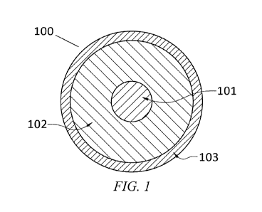
[00044] FIG. 1 illustrates a general cross sections of embodiments of the
present inventions depicting combination of materials, geometric shape,
electrical, and
dielectric members used to construct a submersible electrical transmission
system.
[00045] FIG. 2 illustrates a the preferred embodiment of this invention,
constructing an electrically conductive insulated and shield copper beryllium
alloy tube
having a coaxial cavity along the length of a electrical transmission to form
a
submersible electrical transmission system.
[00046] FIG. 3 illustrates the preferred embodiment of this invention methods
of logging wells with a submersible electrical transmission system comprising
a tube in a
submersible environment of a well bore wherein an electrically conductive,
insulated,
and shielded beryllium copper alloy tube is used to transmit hydraulic fluid
to an
elastomeric subterranean device whilst transmitting electrical power down the
same
logging tube to electrical devices.
[00047] FIG. 4 illustrates the cross-sectional view of the preferred
embodiment of a submersible electrical transmission system having an optical
fiber
loosely disposed in the coaxial cavity of an electrically conductive shielded
beryllium
copper alloy insulated tube.
[00048] FIG. 5 illustrates the preferred embodiment of a process for
constructing and combining materials to form a submersible electrical
transmission
system having an electrically conductive shielded beryllium copper alloy
insulated tube.
DETAILED DESCRIPTION OF THE INVENTION
[00049] As used herein, "a" or "an" means one or more. Unless otherwise
indicated, the singular contains the plural and the plural contains the
singular. For
example, as used herein, the term "logging tool" includes both a single
logging tool and
more than one logging tools arranged in any way, such as a suite of logging
tools.
Where an apparatus is said to comprise a logging tool, that apparatus should
be
understood include a single logging tools or a suite of logging tools. As used
herein,
unless otherwise indicated or otherwise clear from the context, the word "or"
includes
both the conjunctive and the disjunctive and means "and and or", sometimes
written as
13
un cM1lP p0011W0 CA 02794452 2012-09-25
WO 2011/119874 PCT/US2011/029852
"and/or". Thus, the phrase "transmission of electrical power or data", should
be
understood to mean "transmission of electrical power and/or data". Thus, the
present
invention therefore encompasses all three of the following: 1) conduits for
transmission
of both electrical power and data, 2) conduits for transmission of electrical
power alone,
and 3) conduits for the transmission of data alone. Similarly, the invention
encompasses
methods of transmitting all three of the following: 1) electrical power and
data, 2)
electrical power alone, and 3) data alone.
[00050] As used herein, "line", when used in terms of a transmission line,
encompasses single wire, a bundle of wires, a rod, or a tube which may contain
wires,
optical fibers, electrical devices and combinations thereof.
[00051] As used herein "submersible" means capable of being deployed below
a surface. The surface can be a land surface or the marine surface. Thus,
"submersible"
means both marine-submersible and subterranean submersible. The term "marine-
submersible" means both of 1) below the water surface but above the seafloor,
and 2 )
below both the water surface and the seafloor.
[00052] As used herein, "surface" means locations at or above the surface of
the earth. The term surface includes both 1) a water/air surface such as those
in marine
and non-marine bodies of water, and 2) an earth/air surface on land (i.e., the
ground).
[00053] As used herein, "electrically conductive" is electrical conductivity
greater than 1% of the International Annealed Copper Standard, (IACS), wherein
this
standard is based on an annealed copper wire having a density of 8.89 g/cm3, 1
meter in
length, weighing 1 gram, with a resistance of 0.15328 ohms. This standard is
assigned
the value 100 at 20 C (68 F).
[00054] As used herein, yield strength or yield point, of a material is
defined
as the point on a stress versus strain curve wherein a material begins to
deform
plastically, hence any load that increases the stress beyond this point will
permanently
and irreversibly deform the material. Some materials do not have well defined
yield
points or a yield strength, it is therefore convenient in engineering science
to define the
yield strengths by the "offset yield method, wherein a line is drawn parallel
to the linear
elastic portion of a material's stress strain curve intersecting the abscissa
at a value of
0.2% of strain and the stress strain curve for the material. The intersection
of this line
14
un -,T%ATlP poO11WO CA 02794452 2012-09-25
WO 2011/119874 PCT/US2011/029852
and the stress-strain curve of the given material is defined as the 0.2%
offset yield
strength.
[00055] As used herein, the term, "alloy which may obtain" refers to the art
of
modifying the properties of alloys by thermal, mechanical, electromagnetic
methods,
including but not limited to, tempering, quenching, annealing, aging, drawing,
peening,
electromagnetic pulsing, aging means and methods well know to those in the
field of
metallurgy wherein the alloys of this inventions electrical and mechanical
properties can
be enhanced by the methods and means including but not limited to, series of
process
steps of heating, annealing, drawing, cooling, quenching, peening, aging, and
otherwise
aging, mechanically and thermally working the alloys to impart desired
properties into
the grain structure of the alloy. The term "alloy which may obtain", is then
understood
by those familiar to the art of metallurgy to include means to impart various
properties to
an alloy, including the alloys described herein. This includes any number of
process
steps and combinations thereof imposed upon the alloy during processing of the
alloy
and/or processing of the alloy into a finished product or thereafter in the
shaping of the
alloy, including but not limited to, melting, casting, hot rolling, cold
rolling, solution
annealing, age hardening, precipitation-hardening, mechanical deformation,
solution
annealing, temperature controlled curing, and aging, from the original wrought
melt of
an alloy to the finial shaping of the alloy into a geometrical shape or
device.
[00056] The present invention is directed toward a electrical power/data
transmission line for use in the oil and gas industry, said electrical
power/data
transmission line also being a structural member having enough tensile
strength to
withstand the hanging load of its own weight over at least 1000 feet (304.8
meters).
[00057] Attention is first directed to FIG. 1 wherein one embodiment of the
present invention is shown. Briefly, FIG. 1 illustrates a cross-section of an
embodiment
of the electrical power or data transmission device. The device 100 is an
electrical power
or data transmission conduit and signal system conduit having an inner
electrically
conductive beryllium alloy member 101, comprising, in the preferred
embodiment, a
beryllium copper alloy member, which is encapsulated in a dielectric material
102. A
preferred dielectric material is amorphous polyimide. One non-limiting example
of such
an amorphous polyimide is commercially available from Richard Blaine
International,
Inc of Reading Pennsylvania; although others should be suitable as well. In
the
un -,rani nrro11WO CA 02794452 2012-09-25
WO 2011/119874 PCT/US2011/029852
embodiment of FIG. 1, encapsulating the dielectric material 102 is layer 103
which
forms the final layer and thus the outermost surface of the system of the
embodiment of
FIG. 1. In preferred embodiments, outer material 103 is a conductive material
which
forms a mechanical shielding encapsulation around the dielectric material 102.
One
embodiment of fabrication of the device utilizes the placement of multiple
layers of a
polyimide dielectric material 102 to be cured onto a beryllium alloy member
101, which
may be accomplished by passing the beryllium alloy member 101 through a series
of
curing stations after the dielectric encapsulation material 102 is applied to
the surface of
the beryllium alloy member 101. Preferably, encapsulation layer 103 serves as
the
outermost encapsulation of the submersible electrical transmission conduit
100, and in
preferred embodiments uses a polymer doped with elements which enhance the
electrical
conductivity properties of encapsulation 103. The elements incorporated as
dopant are
well known to those engaged in the production and use of submersible and
include zinc,
tin, copper, iron, and other electrically conductive materials. Alternatively,
encapsulation 103 may be a more conventional conductive material, such as a
metal or
metal alloy such as zinc or tin.
[00058] In another aspect of the present invention there are methods of
sputtering electrical conductive elements onto the outer encapsulation surface
of
dielectric encapsulation 102 forming an outer encapsulation 103 with enhanced
electrical
conductivity and shielding properties. Use of polymeric solutions in both
encapsulation
layer 103 and encapsulation layer 102, that when cured are in an amorphous
state, allows
the submersible electrical system to be flexible for storage on reels, for
well logging
intervention methods, powering submersible devices like logging tools,
submersible
electrical motors attached to submersible well pumps, submersible electrical
motors for
drilling allowing for the encapsulation to be receptive to sputtering methods.
However,
it should be understood that other, preferably flexible, claddings, may be
used. It can
now be seen that this embodiment teaches the combination of novel new
materials of
construction, methods of construction thereof, and component arrangements to
form an
easily deployable, repairable, and extendable electrical power transmission,
data signal
transmission, and data collection lines which may be used for well logging,
and
powering permanently deployed measuring devices. Such devices include
pressure,
temperature, and acoustic devices, submersible umbilical cables for powering
submarine
devices, subterranean power transmission to power fluid lifting devices, and
marine and
16
un QAAnR p0011WO CA 02794452 2012-09-25
WO 2011/119874 PCT/US2011/029852
aeronautical antennas for the collection of data using methods known to those
in the field
of aerospace as Synthetic Aperture RADAR Systems (SARS), and Synthetic
Aperature
Sonar Systems, (SAS) and other marine and aeronautical data gathering methods
wherein a long hollow embodiment of my invention is used as an antenna and or
receiver
capable of transmitting electrical power whilst receiving echo captures at
multiple
antenna positions with receiving devices disposed on or in said antenna. For
example,
layer 103 can also be a zinc, tin, or other material wrapped, sputtered, or
doped onto
layer 103 to form the outer shield as opposed to polymeric coatings.
[00059] A further aspect of this invention is shown in FIG 1, namely, that the
outer encapsulation 103 need not comprise an electrically conductive member.
This
invention includes embodiments wherein electrical grounding of a submersible
system is
largely conducted through electrical submersible device connected to the
submersible
electrical transmission system of the invention. Non-limiting examples of such
electrical
devices are submersible electrical three phase motors, and three-phase
electrical cables
including those made commercially available by Baker Centrilift of Claremore
Oklahoma, Schlumberger Reda of Bartlesville Oklahoma, and Electrical
Submersible
Pump Incorporated of Midwest City Oklahoma wherein the three electrical
conductors of
the submersible cable are connected at a "Y" in the electrical motor and the
ground is
then largely achieved through the motor and pump assembly to the well casing.
The
submersible structural electrical motor cables of the present invention
incorporates three
each of the cables of the invention shown as an apparatus 100 in FIG. 1, or
200 in FIG. 2
wherein the three said cables of the invention are packaged into a cable
bundle for the
supplying of three-phase electrical power to a submersible electrical motor.
Currently,
the electrical submersible cables for the electrical submersible motors used
to power
submersible pumps are made of copper and thus do not have sufficient yield
strength to
support their own weight and thusly must be attached or encapsulated in
another strength
member. The most common way that this problem is overcome in the current art
is to
attach electrical cable to the outer diameter of a production tubing string
that is also
deployed. Another means currently used by the oil and gas industry to support
electrical
power cables for electrical submersible motors involves disposing the
electrical cables
inside a continuous steel coiled tubing. In either case, the current industry
electrical
submersible pump systems are directed toward the use of non-electrically
conductive
member means to support the electrically conductive members of the submersible
pump
17
un cr4r)u p1)011WO CA 02794452 2012-09-25
WO 2011/119874 PCT/US2011/029852
cables. The present invention encompasses a novel submersible electrical pump
cable
system that uses an electrically conductive beryllium alloy as a strength
member and an
electrically conductive member of a submersible electrical motor cable. The
present
invention also includes the use of the apparatus 200 of FIG. 2 wherein at
least one
portion of an electrical submersible cable comprises an electrically
conductive beryllium
tube 201. This tube is then used for the transmission of electrical power, and
for the
transmission of fluids to the submersible environment. The use of cavity 204
shown in
FIG. 2 inside an electrically conductive beryllium alloy tube has advantages
not realized
by the electrical wire cables now used by the industry. These advantages of
the
electrically conductive strength member tube of the present invention include
the
injection and circulation from surface of dielectric fluids into submersible
electrical
motors, the injection of treatment chemicals for oil and gas wells (including,
but not
limited to, scale and corrosion inhibitors) through 204 of the apparatus 200
of FIG. 2,
and the inflation of elastomeric sealing elements and devices in subterranean
environments by pumping fluids from surface through the electrically
conductive
member 201 of apparatus 200 of FIG. 2, whilst simultaneously having the
ability to
transmit electrical power (and/or data) from surface to the down hole
electrical pump
through the electrical conductive beryllium alloy 201 in FIG. 2. The use of
non-
electrically conductive outer encapsulation of the beryllium alloy electrical
conductive
system of the present invention for electrical submersible motors is discussed
herein by
the way of an example and is not meant to be limiting. Clearly, the novel use
of the
methods of the present invention can be used to power many down hole
electrical
devices including pressure gauges, temperature gauges, solenoids, heaters,
transmitters,
receivers, and other well known electrical submersible devices.
[00060] Attention is now drawn to FIG. 2, which illustrates an alternative
embodiment which comprises a submersible electrical power or data transmission
conduit 200, wherein a beryllium alloy tube 201 is encapsulated in a amorphous
dielectric material 202, which is itself encapsulated by an outer electrically
conductive
shielding encapsulation 203. FIG. 2 further illustrates an embodiment where a
submersible electrical transmission system is arranged in a configuration that
constitutes
an electrically conductive hydraulic tube having a coaxial cavity 204. The
coaxial cavity
204 maybe filled with inert gases, dielectric fluids, magnetic fluids, high
magnetic
18
un QAifTID DrtO11WO CA 02794452 2012-09-25
WO 2011/119874 PCT/US2011/029852
permeability materials, wave guides, electrical conductors, magnets,
electromagnetic
transmitters or receivers, or a vacuum.
[00061] FIG. 3 illustrates an exemplary sketch of the preferred embodiment of
the present invention in a land-based operation. In FIG. 3, a method of well
logging with
a submersible electrical beryllium copper alloy transmission logging tube
system is
depicted. A logging tube comprising a submersible electrical transmission
conduit 10 is
deployed into a subterranean well 4, the submersible electrical transmission
conduit of
this specific embodiment comprises a beryllium copper alloy tube having a
coaxial
cavity tube forming a portion of a submersible electrical transmission conduit
10 and the
cross section if which is illustrated in FIG. 2. The submersible electrical
power or data
transmission conduit has a proximal end 5 at a surface location and a distal
end 6 in a
subterranean location wherein the submersible environment is separated from
the surface
environment around the submersible electrical transmission system 10 by an
elastomeric
seal 18 located on top of a wellhead 23 wherein the seal 18 is expanded around
the
submersible electrical transmission line 10 with hydraulic fluid from a
hydraulic pump
system through hydraulic line 20.
[00062] FIG. 3 further illustrates the beryllium copper alloy tube submersible
electrical transmission system reeled onto a coil tubing reel 7 and attached
at surface to a
pump 8 pumping a fluid from a surface reservoir 9 into the submersible
electrical
transmission line 10 to inflate a subterranean elastomeric packer device 11
while
transmitting electrical power or data signals (which can be analog or digital
signals) to
and from a suite of logging tools 12. FIG. 3 further illustrates a crane 22
suspending
over well head 23, a coiled tubing injector head 13 engaging the electrical
transmission
line 10 to inject, hold, and retrieve the transmission line from the
submersible
environment of the well 4. FIG. 3 further illustrates the transmission of
electrical power
or data signals into and through the transmission line 10 at a slip ring 14
where electrical
current is conducted from a logging truck 15 whist pumping fluid with pump 8
during
both dynamic deployment of the logging tube or in static positions in the
well. The slip
ring enables the simultaneous transmission and collection of electrical power,
data,
optical power and signals, and transferring the same to surface data
collection equipment,
and computerization equipment attached to the data and power transmission
system 10 of
this invention. In the preferred embodiment, data is collected through a data
line 16
19
it c14r\D DoO11WO CA 02794452 2012-09-25
WO 2011/119874 PCT/US2011/029852
disposed inside the logging tube, connected to computer 17 and/or other
devices 17
known to those of skill in the art, and transmitted inside the logging truck
15 to computer
and data storage devices. The data line 16 can be an electrical wire, and
optical fiber as
illuminated in FIG. 4.
[00063] FIG. 4 depicts another embodiment of a transmission conduit 300
comprising at least one additional member 304 disposed inside the beryllium
alloy tube
301. The preferred embodiment comprises at least one optical fiber 304
encapsulated in
a polymeric material 305 wherein the optical fiber cable is loosely disposed
inside the
beryllium alloy tube 301 which is encapsulated in an amorphous dielectric
material 302
which is further encapsulated on the outer surface with an amorphous polymeric
electrically conductive material 303. This additional member 304 in the
preferred
embodiment extends from surface at the proximal end (not visible in FIG. 4) of
conduit
300. Member 304 is connected to a computer (not shown) and the distal end is
in the
well (not shown). As would be recognized by those of skill in the art of
optical fiber data
transmission, if the optical fiber 304 breaks, darkens or otherwise needs to
be replaced
by another optical fiber cable, the arrangement of a logging tube shown in
FIG. 3 allows
for the previously loosely-disposed optical fiber to be removed from the
conduit space
204 of FIG. 2 and readily replaced with a different optical fiber cable. It is
also
understood by those familiar with the construction of continuous tube that the
optical
fiber 304 of FIG. 4 can be replaced or combined with electrical wires, or a
combination
of electrical wires, optical fibers, and electrical devices.
[00064] Again referring to FIG. 4, the beryllium copper electrically
conductive
logging tube 301 is depicted having an optical fiber 304 disposed therein.
Optical fiber
304 could also comprise at least one electrical wire without departing from
the scope of
this invention. In either case of an optical fiber or an electrical wire, both
can be
depicted as encapsulated in a dielectric material 305 disposed inside the
coaxial cavity of
the beryllium copper alloy tube 301 where the beryllium copper alloy tube is
encapsulated in at least one dielectric material 302 which is further
encapsulated in a
electrically conductive material 303. This outer electrical conductive
material acts as a
shield for both mechanical and electromagnetic effects on the system by the
conductance
of the submarine or subterranean environment. This outer material layer 303
aides to
un QAITfP p()011WO CA 02794452 2012-09-25
WO 2011/119874 PCT/US2011/029852
increase bandwidth on the submersible electrical system by increasing the
inductance
loads on the system like a Faraday cage.
[00065] In a preferred embodiment, a conduit comprising an optical fiber is
used in conjunction with an Optical Time Domain Reflectometry (OTDR) device as
a
logging tool, either alone or as part of a suite of logging tools. However, it
is important
to note that any and all analytical logging methodologies, devices, and
attachments
suitable for or amenable to use in a well environment can be used as logging
devices
attached to the submersible electrical beryllium copper alloy tube
transmission system
described herein without departing the scope of this invention. This includes
all
spectroscopic and non-spectroscopic analytical methods, any and all
temperature,
pressure, acoustic, pulsed neutron, resistivity, and combination flow
measurement and
interpretation methods, of which are familiar to those of skill in the art of
well logging.
It should be understood that inserting a logging tool into a well bore
comprises inserting
some or all of the logging tools currently known in the art of oil and gas
logging as well
as well completion methods, wherein recording and injection devices are
disposed
permanently in submersible environments using beryllium copper alloy
electrically
conductive members. These and other variations should be considered within the
scope
of this invention as the use of any such permanent deployed systems and
devices does
not depart from the teachings of this invention.
[00066] In the case of the use of an OTDR device, the optical fiber is at
least
one of the component of the beryllium copper alloy tube system. The optical
fiber is
inserted into the well and extends to the surface, while preferably, the
computer
hardware, data recording, backscattered light monitoring, and LASER source
that launch
the light into the optical fiber preferably remain above the surface or other
remote
location. Gamma ray detection recording devices, electro-magnetic collar,
density
neutron, resistivity, electrical acoustical, pulsed neutron tools, detection
recording
devices, cameras, video recorders and perforating guns, explosive tool setting
devices,
are additional, non-limiting examples of logging and perforating tools that
can be used in
the present invention.
[00067] Those familiar with the art of metallurgy refer to peening or shot
peeing as a means to impinge particles at a high velocity onto a surface. In
the present
21
un QTITTII? pOOIIWO CA 02794452 2012-09-25
WO 2011/119874 PCT/US2011/029852
invention, peening may be used in the construction process to modify the
surface of a
beryllium copper material.
[00068] Those of ordinary skill in the art of well logging refer to a
plurality of
tools and devices used to log wells as a suite of logging tools. A suite is
formed by
connecting one or more logging devices together into a train of tools lowered
simultaneously into the well. A suite of tool can therefore comprise many
combination
of devices, instruments, and data transmission systems that a well engineer
can select to
gather the required well data. For example, a typical production logging suite
of tools
would include a flow meter device known as a spinner, a pressure measurement
device
often a strain gauge, a gamma ray device that monitors the radio-activity of
the
subterranean lithologies versus depth for depth correlation, a magnetic
monitoring device
often referred to as a casing collar locator that correlates the number of
casing collars
with the depth of the logging suite, an optical fiber inserted with the
logging tube, that
measures temperature and acoustics along its length to yield well profiles of
temperature
and sound, and many other combinations of logging tools that can be included
in a
logging tool suite. All such devices can be coupled to the transmission
conduit of the
present invention to realize performance advantages as well as increased
durability.
[00069] As discussed above, the term "logging tool" includes both a single
logging tool device or more than one logging tool device arranged in various
combinations common to those familiar with the art of well logging, such that
a suite or
combination of logging tools are deployed simultaneously, and articulated in
and out of
the well with the submersible electrical transmission system and coiled tubing
methods
herein taught. While the preferred embodiments involve methods which use the
conduit
of the present invention as a beryllium alloy logging tube, it should be
understood that
the conduit may take the form of beryllium alloy rod, beryllium alloy wire,
and
combinations of the beryllium alloy wire, rod, and tube. For example, it will
be
understood by those familiar with the art of well completions that in certain
wells, like
horizontal wells, it becomes advantageous to push this inventions beryllium
alloy rod as
opposed to tube members, or wire members. The choice of form is dictated by
the
logistical and other considerations that are extant in the project at hand.
[00070] It will be clear to those familiar with the art of oil and gas
production
that certain wells and certain well conditions will require this inventions
beryllium alloy
22
un QT'Ann "()O11Wo CA 02794452 2012-09-25
WO 2011/119874 PCT/US2011/029852
rod, while others will require beryllium alloy wire, while still others will
require
beryllium alloy tubes. However, the preferred embodiment of the present
invention is
the use of the beryllium alloy tube member wherein the tube alloy has multiple
synergistic attributes. These attributes comprise an electrical conductor
member, a
hydraulic transmission member, an electrical wire encapsulation member, an
optical
wave guide encapsulation member, and afford a novel an improved repairable
submersible electrical logging system. Moreover, those familiar with the art
of data
collection will recognize that the beryllium tube can contain transmission
devices and
receiving devices allowing the beryllium tube to be disposed in environments
as single or
distributed arrays. These attributes have the useful industrial purpose of
reducing the
overall size, weight, and cost for many applications including, but not
limited to, well
logging while overcoming the shortcomings of prior art related to repairing
the wire line
logging cables, leaking grease injectors, and the lack of hydraulic power
means. The
improvements of this invention eliminate the well logging current industry
problems of,
leaking lubricators, grease injector, and crushing of electrical cable on
logging drums. In
the preferred embodiment, the beryllium alloy is a copper beryllium alloy tube
which has
a beryllium content of 0.2% to 2.5% by weight and can thusly support its own
weight, be
used with coiled tubing injector devices thereby reeling this inventions
electrically
conductive logging tube without wrapping loads as are common on current
technology
wire line logging methods. In the most preferred embodiment, the beryllium
alloy has
0.2% to 0.6% beryllium, 1.4% to 2.2% nickel, with the remainder being copper.
[000711 FIG. 3 illustrates one exemplary use of the electrical power or data
transmission conduit of the present invention, involving a well logging method
with a
beryllium alloy logging tube. It shows the step of well logging with the
transmission
conduit performed with a coiled tubing injector head 13, by inserting the
submersible
electrical transmission system into the submersible wellbore 4 below a fluid
level 21.
Nevertheless, other alternatives may be used. For example, the submersible
electrical
transmission system can be configured as a wire line cable and may be placed
in a
pressure lubricator on top of a wellhead, wherein weight bars and or a logging
tool suite
are connected and hung from the distal end of the submersible transmission
system, the
top of the system is sealed with a grease injector device familiar to those in
the wire line
logging industry, and the weighted logging tool suite is lowered into the well
by a
surface capstan device commonly known as a wire line drum, typically located
on a well
23
un ox,1T D Dr)OIIWO CA 02794452 2012-09-25
WO 2011/119874 PCT/US2011/029852
logging truck and well known to those familiar with the art of well logging.
In an
alternative embodiment, the submersible transmission system can be inserted
into a well
bore by pumping means (such means include, but are not limited to, triple
pumps,
centrifugal pumps, progressive cavity pumps, etc.) wherein the drag and fluid
is used to
transport the beryllium alloy electrical conductor member into a well.
Further, the
submersible transmission system can be retracted from the surface with capstan
devices
well known to those familiar with the art of well logging.
[00072] This invention includes the use a submersible electrical transmission
system which comprises a submersible fluid sampling device on the distal end
of the
system. In this way, fluids from a submersible location of interest can be
sampled.
[00073] In some instances the submersible electrical transmission is connected
to a submersible logging tool suite which may also comprise at least a fluid
pressure
monitoring device, a fluid sampling chamber, a gamma ray logging tool, and
density
logging tool, a electromagnetic logging tool, and other subterranean devices
known to
those familiar with the art of well logging.
[00074] Attention is now drawn to FIG. 5 demonstrating a preferred method of
constructing a beryllium copper alloy tube apparatus by converting a soft heat-
treatable
beryllium copper alloy strip into a long tube of shielded, insulated, and
enhanced
beryllium copper alloy for optimal mechanical and electrical properties.
Although this
example focuses on beryllium copper, it should be understood that other
beryllium alloys
are also applicable. FIG. 5 depicts a reel, item 401, of soft heat treatable
copper
beryllium strip 402 presented at the beginning of the process. The
construction process
is started by attaching one end of a length of a "pulling dummy tube" to the
strip 402 by
an attachment means (such attachment means include, but are not limited to,
weldments,
ferrule fitting connectors, etc.) and running the "pulling dummy tube" through
the mill
and around the capstan 403 and terminating on collection reel 404 for tube at
the distal
end of the mill. The process is further depicted in FIG. 5 by showing the
pulling of
beryllium copper strip 402 from the reel 401 with the capstan 403 powered by
an
electrical motor 405. The strip is formed into a tube shape over a series of
roller stations
depicted as 406 and 407 in FIG. 5 as strip is pulled and formed into a tube
shape through
the mill with the capstan 403 and collected on the reel 404 at the end of the
tube mill
process. It is clear to those familiar with the art of tubing mills that the
quantity of roller
24
un erArly "r)011WO CA 02794452 2012-09-25
WO 2011/119874 PCT/US2011/029852
stations can be changed as required by the material and the diameters of tube
outer
diameter one wishes to form without avoiding the spirit of this invention.
Once the strip
402 is converted and transformed into a tube geometrical shape the tube is
welded at
station 408 with a TIG welding system as the strip is continually pulled
through the
process by the capstan. It is important to note that at station 408 that the
welding gases
and dust are captured and circulated to a dust collector and water bath
separator 410 to
where they are collected. It is clear to those familiar to the art of
continuous tubing
manufacturing that the welding device 408 can be comprise other welding means
including LASER welding means using for example LASER devices and/or any other
devices known to those of skill in the art. After welding, the tube is pulled
through a
high temperature annealing station 411 to relieve stresses in the tube from
welding and
homogenizing the matrix grain structure of the beryllium copper alloy. It is
clear to those
familiar with the art of tubing mills and alloy metallurgy that the residence
time in the
annealing station 411 can be controlled by increasing the length of the
annealing station
411 or slowing the speed of the mill process by means of slowing the capstan
pulling
speed. Likewise, it is clear to those familiar with the art of metallurgy that
different
alloys require different annealing temperatures and residence times which can
be
adjusted by controlling the annealing stations temperature and mill speed.
Very long
annealing stations can be formed using stationary furnace designs and the
designs can
anneal the tube in inert and noble gas environments all of which do not depart
from the
scope of this invention. The tube is pulled forward by the capstan 403 and
passes next
through a quenching station 412 where it is cooled then onto a mechanical
drawing
station 413 where the diameter is reduced mechanically thereby changing the
mechanical
and electrical properties of the tube. The tube is then collected on the
collection reel
404. The tube now collected on reel 404 is then moved to a batch furnace 414
where the
tube is optimally heated and aged at controlled heat up rates, held at
temperature, and
then cooled down as required to reach the optimal electrical and mechanical
properties of
the alloy. It is clear to those familiar with beryllium alloy metallurgy that
many
schedules of heating, time aging, and cooling can be performed to optimize the
properties required of the tube and such schedules depend on the exact
constituents of
the beryllium copper alloys. Once the tube on reel 404 has obtained the
require
mechanical and electrical properties in the furnace 414 it is removed from the
batch
furnace 414 and presented to the beginning position 415 of an encapsulation
mill. The
un crams r OIIWO CA 02794452 2012-09-25
WO 2011/119874 PCT/US2011/029852
mechanically and thermally enhanced tube 416 is connected to a dummy pull tube
with
an attachment means such as a weld or feruled connector device (although other
equivalent means may be used) and run through a encapsulation mill depicted in
FIG. 5
by pulling the tube through the encapsulation mill stations with the capstan
417 and
collecting the encapsulated tube on the collection reel 418. The first station
that tube 416
passes through in the encapsulation mill is a cleaning bath 419 progressing
thereafter to
the encapsulation bath 420 where a polyimide fluid 421 (other dielectric
materials may
be used) is applied to the tube outer diameter and heated and cured in a
vertical furnace
422 and then the tube is pulled continuously through to a sputtering station
423 where
materials are added to coat the encapsulating and subsequently the tube is
further pulled
and progressed to a cooling station 424 and on through to the capstan 417
which is
driven by the electrical motor 425 and then collected on reel 418. This
encapsulation
process can be repeated multiple times, thereby placing multiple coatings and
sputtering
materials on the continuous tube assembly. Also a given continuous tube can
pass
through several encapsulation mills which may be used each to coat and
encapsulate
using different materials, different curing temperatures, and transient times.
[00075] In almost all applications in the oil and gas industry, the structural
member/conduit will have a length of greater than 1000 feet (304.8 meters). In
typical
applications, it will have a length of greater than 3000 feet (914.4 meters).
In other
applications, it will have a length of greater than 5000 feet (1524 meters).
In some
applications, such as deep-sea oil and gas operations, it will have a length
of greater than
7000 feet (2133.6 meters), and in some cases, greater than 10,000 feet (3048
meters).
[00076] The beryllium alloy conductive conduit preferably has an electrical
conductivity value greater than 25% of the International Annealed Copper
Standard
(IACS). However, in some applications, it may have an electrical conductivity
value
greater than 1% of IACS. In other applications, it may have an electrical
conductivity
value greater than 10% of IACS. In other applications, it may have an
electrical
conductivity value greater than 30% of IACS. In other in some applications, it
may have
an electrical conductivity value greater than 40% of IACS. In other
applications, it may
have an electrical conductivity value greater than 50% of IACS. In yet other
applications, it may have an electrical conductivity value greater than 60% of
IACS. In
other applications, it may have an electrical conductivity value greater than
70% of
26
un CI~~TT1R pn0iiWO CA 02794452 2012-09-25
WO 2011/119874 PCT/US2011/029852
IACS. In other applications, it may have an electrical conductivity value
greater than
80% of IACS. The choice is variable depending upon the particular application
and the
combination of conductivity and strength needed.
[00077] In the preferred embodiment, the structural member comprises the
electrical conduit. In all cases, a significant portion of the overall
mechanical strength
(and in most cases, substantially all of the overall mechanical strength of
the structural
member) is provided by the electrical conduit. Because a primary advantage of
the
present invention is an electrical conduit also acting as a strength member,
in some cases,
the structural member and the electrical conduit are one and the same and no
other
components are present. In other words, in such cases the structural member
consists of
the electrical conduit. However, in some cases, the structural member may
consist of
some additional components that do not significantly affect overall strength
of the
member; in such cases the structural member consists essentially of the
electrical
conduit.
[00078] It should be understood that variations, changes, and substitutions
recognized by those of ordinary skill in the art upon a reading of this
disclosure are
within the scope of the invention. For example, the continuous beryllium
copper alloy
tube collected at the end of the mill on reel 404 maybe connected to another
reel of
tubing with a butt weld, and the two adjoined continuous tubing lengths now
form a
substantially longer continuous tubing length and thereafter can be run
through a similar
milling process further drawing down the size of outer diameter of the
substantially
longer continuous connected tube lengths. These butt welded tube lengths can
also be
drawn over a mandrel in a mill process. It is further understood that this
weld connection
of two or more continuous lengths can be made with welding TIG means or
electromagnetic pulse welding means to avoid a heat affected zone at the butt
welds.
[00079] Although the present invention and its advantages have been
described in detail, it should be understood that various changes,
substitutions, and
alterations can be made to the process discussed herein without departing from
the spirit
and scope of the invention as defined by the appended claims. Moreover, the
scope of
the present application is not intended to be limited to the particular
embodiments of the
process, machine, manufacture, composition of matter, means, methods and steps
described in the specification. As one of ordinary skill in the art will
readily appreciate
27
un cXanu pf)ol lWO CA 02794452 2012-09-25
WO 2011/119874 PCT/US2011/029852
from the disclosure of the present invention, processes, machines,
manufacture,
compositions of matter, means, methods, or steps, presently existing or later
to be
developed that perform substantially the same function or achieve
substantially the same
result as the corresponding embodiments described herein may be utilized
according to
the present invention. Accordingly, the appended claims are intended to
include within
their scope such processes, machines, manufacture, compositions of matter,
means,
methods, or steps.
28