Note: Descriptions are shown in the official language in which they were submitted.
WO 2011/128670 PCT/GB2011/050707
1
Description
A CASK
Technical Field
[0001] The present invention relates to a cask for storing and "maturing"
distilled spirits,
particularly whisky (alt. whiskey).
Background Art
[0002] A traditional whisky cask is a bilge-barrel shape, formed by a
plurality of curved
staves that result in an overall bulge when it is assembled and bound
together. Such a
bulge (bilge) is useful for manually rolling and controlling the direction of
the cask,
which may weigh 500kg or more, on its side.
[0003] Casks for spirits can be made of any suitable material; however, whisky
casks are
required to be made from oak which is important for the maturation process. It
is
typically found that after several uses (e.g. at intervals of ten years when a
new batch
of spirit is introduced to the cask for maturation) the interior wood of the
cask must be
"rejuvenated" by flailing the surface (e.g. by wire brush) in contact with the
spirit. As
such an average barrel normally has a lifespan of 50 years.
[0004] The general design of whisky casks in common use, made from oak, has
not changed
significantly in many hundreds of years, although some attempt has been made
to
introduce new designs over the years. For example,
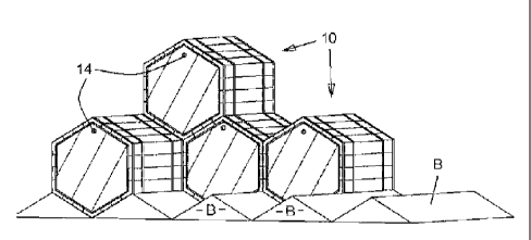
Patent Citation 0001: GB 1136469 A (GEORGE RICHARD MORRIS ; ALVA
DONALD MESSENHEIMER). 1968-12-11.
describes a square ended barrel with the intent to save space in a warehouse;
since
square shapes can pack together more efficiently than a circular/cylindrical
shape that
must necessarily have empty gaps therebetween.
[0005] However, GB 1136469 in fact describes a "cabinet" construction and not
a cask in the
traditional sense. The staves of the cabinet must have a jointing mechanism
and rely on
an elastomeric bonding agent for sealing and cohesion.
[0006] A particular problem experienced with traditional cask designs, i.e.
casks that do not
utilise bonding and/or sealing agents, is that when warehoused (e.g.
palletised upright
or high racked on their bilge; in both cases up to six levels high) the staves
can be
forced apart by sheer weight, causing slow loss of spirit. Loss is also
observed at the
area of the bung where whisky is introduced/removed from the barrel.
Disclosure of Invention
[0007] The present invention therefore seeks to address problems observed with
traditional
whisky casks and provide an alternative.
WO 2011/128670 PCT/GB2011/050707
2
[0008] In one broad aspect there is provided a method of warehousing casks for
whisky,
utilising a plurality of straight walled casks and stacking same such that the
walls are
compressible by the weight of an adjacent cask. Preferably, the casks are
oriented on
their sides and with a corner edge of the cask in a 12 o'clock and/or 6
o'clock position
to obtain the optimum weight distribution possible for acting on all sides of
the cask.
[0009] The casks are preferably comprised of a plurality of staves bound
together to form
hexagonal, triangular or square/diamond prism shapes. Preferably the
ends/sides are of
equal length (i.e. regular hexagon, equilateral triangle, square not rectangle
etc).
[0010] The method may require use of a base with a support surface to fill the
gaps of the
lowermost row of casks.
[0011] The advantage of these shapes is that downward force applied by the
weight of
stacked casks creates a compressed wall structure that will reduce spirit loss
between
the staves that comprise the cask walls.
[0012] Furthermore, the use of a straight stave length makes the cask easier
to construct and
simplifies the rejuvenation process where it is intended to remove timber that
has been
in contact with spirit stored in the cask.
[0013] An associated advantage found in the present invention is the space
economy of
stacking compared to a traditional barrel. It will be appreciated that bilge-
barrel shapes,
even when tightly packed and stacked together, result in significant empty and
un-
fillable space in a warehouse. In the present invention, multiple casks can be
stacked or
nestle to form a bank of like shaped casks with no gaps therebetween.
[0014] As described above, to obtain optimum compression laterally between the
staves in
contact with each other the casks are oriented on their sides with a corner
edge of the
cask wall in a downward (and/or opposing upward, 6 and/or 12 o'clock)
position. For
example, in the case of hexagonal casks, this results in a honeycomb end
appearance
when stacked, requiring a base with a support surface of a jagged shape to
fill the gaps
between the lowermost row of casks and the floor. In the case of a square-
ended cask,
stacking is performed such that there is a diamond appearance. Likewise,
preferably a
jagged (triangular support surface) base is provided that supports the
lowermost row of
casks.
[0015] In a second broad aspect there is provided a cask for whisky
constructed from a
plurality of straight staves bound together to form a prism-shape such that,
when
stacked with other like casks, it is able to result in a self compressing wall
structure.
[0016] The term "bound" implies use of a high-tension strap or equivalent and,
specifically,
the absence of bonding or sealing agents between the staves. The avoidance of
chemical agents ensures that no adverse taste can be imparted to the spirit
housed by
the cask during the maturation process.
[0017] Preferably the prism-shape is a hexagonal prism. The shape may also be
triangular.
WO 2011/128670 PCT/GB2011/050707
3
In another form the shape may be square/diamond ended. These most preferable
shapes are such that no gaps form between adjacent casks when stacked in a
warehouse.
[0018] It will be apparent that a plurality of casks according to the second
aspect of the
invention can be utilised in a warehousing system that follows the method of
the first
aspect of the invention. Specifically, according to a third aspect there is
provided a
system of warehousing casks for whisky, utilising a plurality of casks
constructed from
a plurality of straight staves bound together to form a prism-shape wherein
the casks
are oriented on their sides and with a corner edge of the cask in a 12 o'clock
and/or 6
o'clock position.
[0019] Preferably the system includes a support surface with ridges upon which
a lowermost
row of casks is in contact.
Brief Description of Drawings
[0020] Figure 1 illustrates an underneath view of a cask according to a first
embodiment,
[0021] Figure 2 illustrates a frontal isometric view,
[0022] Figure 3 illustrates a side view,
[0023] Figure 4 illustrates a view of a plurality of casks according to the
first embodiment of
the invention stacked for storage,
[0024] Figure 5 shows a side wall for a cask of the invention,
[0025] Figure 6 shows a partially assembled cask according to the invention;
[0026] Figure 7 shows a frontal view of a cask according to a second
embodiment of the
invention,
[0027] Figure 8 shows a view of a plurality of stacked casks according to the
second em-
bodiment,
[0028] Figure 9 shows a second view of a plurality of stacked casks according
to the second
embodiment, and
[0029] Figure 10 shows a plurality of stacked casks according to a third
embodiment of the
invention.
Mode(s) for Carrying Out the Invention
[0030] Figures 1 to 3 show general views of a whisky cask according to a first
embodiment
of the invention. A cask 10 is assembled from a plurality of staves 11
arranged around
a hexagonal end 12 which itself is formed from several lengths of oak. The
staves are
bound together by several straps 13 that are tensioned and joined in a
conventional
manner. Ideally a strap 13 is placed at each end of the cask to compress the
staves
against the hexagonal ends 12 such that they are sealed therewith.
[0031] Stave edges may be constructed with tongue-in-groove joints to assist
assembly. This
is distinguished from other construction methods that require adhesives or
other
WO 2011/128670 PCT/GB2011/050707
4
mechanical fasteners (e.g. bolts or screws) that may affect the taste of the
stored spirit.
An alternative to a tongue-in-groove joint is a convex radius mating with a
matching
concave radius, however, any suitable joining method could be employed.
[0032] Figures 2 and 3 each show an access/bung hole 14 located at a corner of
the
hexagonal cask shape. It is intended that, when stacked, the hole will always
be in the
uppermost corner (12 o'clock position) to minimise leaking. Preferably, spirit
is filled
to just below the level of the hole which, it will be appreciated, results in
less volume
wastage than a conventional cask that has a round end and bulged shape, i.e.
because in
such a conventional cask there will be a greater empty volume above the fill
line in a
cask that is otherwise the same capacity as the cask of the invention.
[0033] When first filled the casks can be in a horizontal (Figure 2) or
vertical orientation.
They are then moved (e.g. by forklift or other mechanised means) into a
stacked
position which may also be a vertical configuration, but preferably according
to the
method of the invention, horizontal (i.e. hexagonal ends 12 showing) as
illustrated by
Figure 4.
[0034] In the configuration illustrated by Figure 4 casks 10 are stacked on a
base B
providing a series of shallow triangular supporting surfaces that fill the gap
that would
otherwise form between the lowermost point of the hexagon (the 6 o'clock
position)
and the floor. The support surface could be cast in concrete or be of frame
con-
struction.
[0035] The stack may take an overall "honeycomb" formation having one fewer
cask on
each successive level. In the illustrated example, there is provision to
support four
casks 10 on the base B, followed by three on a second level, then two, then
one
(although it will be noted not all ten casks in the proposed stack are
illustrated).
[0036] Alternatively, a pair of side brackets could be formed on a warehouse
wall or support
structure to receive and stabilise a block of stacked casks 10 to maximise
storage ef-
ficiency in a warehouse in the vertical direction. Referring to Figure 4, base
B supports
four casks 10. On top of these could stack five further casks, followed by a
third row of
four casks, then alternating between four and five casks per level up to any
practical
height. Stacking in this manner most completely takes advantage of the
"self-compressing" nature of the casks according to the invention.
[0037] It is envisaged that, once stacked, the casks may not be moved again
until reju-
venation is required. Liquid can be introduced/removed from the casks via bung
hole
14 in situ with the use of a tanker. Furthermore, casks can be stacked in
rows, back-
to-back (or, more correctly, base-to-base) with an aisle wide enough to allow
access to
each bung 14, e.g. by a cherry-picker.
[0038] The geometry of a system of hexagonal prisms allows a uniform
distribution of
forces and utilises the weight of the full casks to compress the stave joints
and improve
WO 2011/128670 PCT/GB2011/050707
sealing. Furthermore, particularly for a cask located centrally in a back-to-
back stacked
cluster, the only exposed surface is one hexagonal end, minimising air flow
around the
cask as a whole which is associated with spirit loss.
[0039] Figures 5 and 6 illustrate one form of construction for a hexagonal
cask according to
the invention where corner pieces 15 provide the internal angle (120 ) for the
hexagonal configuration while staves 11 make up side walls. It will be
appreciated that
different volumes of cask can be constructed merely by varying the number of
staves
per side. No additional tooling is required (because corners 15 are the same)
except a
new hexagonal end 12 (smaller or larger area) must be supplied.
[0040] As discussed, rejuvenation is a relatively simple (but time consuming)
process where
casks are dismantled, inspected and reconditioned for further use. It will be
appreciated
that a straight stave 17 can be flailed more easily than the curved stave of a
con-
ventional cask. Flailing normally removes wood from the substantive length,
but
leaves the joint channel 16 where end 12 is located. Likewise, end 12 can be
flailed
over its substantive surface, but not in the area where it forms a seal with
the staves.
Alternatively, it can simply be reversed, i.e. the once outer end surface of
the cask can
be turned inward when the cask is reassembled so that "fresh" wood is in
contact with
the maturing spirit.
[0041] Figures 7 and 8 illustrate a second embodiment that is analogous to the
cask of
Figures 1 to 6. In this embodiment the cask 17 has a triangular prism
configuration
such that it can be stacked, once again, to provide a distribution of forces
that tightly
packs the units together thereby minimising spirit loss. The cask 17 also has
a bung 14
located at an uppermost portion (top corner or 12 o'clock position) where it
can result
in even less empty space in the cask than a hexagonal configuration, if filled
to below
the hole.
[0042] Figure 8 shows that the generally equilateral triangle ended casks fit
together in an
alternating flat and upturned position to form a stack. In this case the bungs
14 should
be formed at two different positions, i.e. at a corner and top edge, depending
on what
orientation the cask takes. Such holes can be drilled after stacking prior to
filling.
[0043] As in the case of stacking hexagonal casks, the triangular shape will
naturally lead to
a pyramid type construction (i.e. a first layer of n casks, second layer of n-
1, third of n -
2 etc) if left to be self supporting. It will be appreciated that a side
supporting bracket,
including surfaces to engage with the exposed sidewalls of the stack can be
provided to
enable more space efficient packing in a vertical direction.
[0044] It should be noted that equilateral triangle-faced casks could be
stacked with a flat
side in a vertical orientation (with use of suitable support brackets etc at
the side/base
of the stack) such that bung holes 14 can all be located at an uppermost
corner and,
therefore, a single form of cask can be used.
WO 2011/128670 PCT/GB2011/050707
6
[0045] Figure 9 illustrates an example where all available space is utilised
by employing an
equilateral triangle cask 17 as described, complemented by a smaller right-
angle
triangle cask 18 at the ends of each row.
[0046] It will be appreciated that other triangle variations are possible,
particularly isosceles
configurations, however, an equilateral triangle has a more efficient material-
to-volume ratio.
[0047] It will be clear from the foregoing that the invention is embodied by a
method of
stacking straight-walled casks, to utilise the natural compression between
units that
will minimise spirit loss when packed in a warehouse for an extended time
period. In
this regard, a third embodiment, illustrated by Figure 10, utilises a square-
ended cask
19 that is stacked to result in a diamond nestled configuration, taking
advantage of
similarly natural compression of the staves in the cask as other embodiments.
[0048] Square/diamond-ended casks as stacked according to the method of the
invention,
require a base B comparable to Figure 4, which will support the downwardly
pointed
(6 o'clock) corner of the cask 19. It is also possible, as with hexagonal and
triangular
configurations, to use a side supporting structure to enable more space
efficient
stacking in a vertical direction, rather than the self supporting n-1
successive row con-
figuration as shown in Figure 10.
[0049] Square/diamond casks 19 can each have a bung hole 14 in the uppermost
corner (12
o'clock) when stacked as illustrated, providing similar benefits for filling
as described
in connection with the previous embodiments.
Industrial Applicability
[0050] In general it is intended that all embodiments are able to be
manufactured from
available techniques and materials (i.e. oak).
[0051] The invention has the combined advantages of providing improvements to
minimise
loss of spirit, increase warehouse economy and improve the ease/efficiency of
reju-
venation compared to more traditional barrel designs.