Note: Descriptions are shown in the official language in which they were submitted.
WO 2011/135363 PCT/GB2011/050837
-1-
Vacuum Anchor System
The present invention relates to a vacuum anchor system and particularly to
such a system
suitable for use in a fall protection system.
Fall protection systems, which include fall arrest or fall restraint systems,
are used in order
to provide safety to personnel working at height. For certain applications,
such systems are
known to employ vacuum anchor devices, particularly where required for
temporary
attachment to elevated metallic structures. Such systems can be used in fall
arrest or
restraint systems for use by personnel working on, for example, aircraft wings
and
fuselage; storage tanks; ships and the like. The vacuum anchor system is ideal
for use in
such circumstances because it does not require any permanent fixing structure
(i.e. can be
temporarily attached) and does not therefore damage the surface to which it is
attached.
A remote vacuum source is typically utilised to supply a vacuum to the vacuum
anchor.
The vacuum source commonly utilises a pressurised gas supply connected to a
venturi,
which creates a suction force to draw the base against the surface to which it
is mounted.
The pressurised gas supply may be remote to the anchor, and may supply more
than one
anchor simultaneously. It is also known to provide the gas supply in the form
of a
pressurised gas bottle mounted on the anchor, which obviates the requirement
for pipes
connecting to a remote supply, which can provide a trip hazard when trailing
along the
work surface.
It is necessary for the worker connected to the anchor to be able to move
freely on the
elevated structure, and it is known to rotationally connect the lanyard to the
anchor to
enable this freedom of movement. However, as the worker moves about the
anchor, it is
possible that the lanyard may become tangled with the pressurised gas bottle,
providing an
inconvenience or worse still causing the bottle to disconnect from the anchor,
potentially
releasing the vacuum.
It is therefore desirable to provide an improved vacuum anchor which addresses
the above
described problems and/or which offers improvements generally.
WO 2011/135363 PCT/GB2011/050837
-2-
According to the present invention there is provided a vacuum anchor as
described in the
accompanying claims.
In an embodiment of the invention there is provided a vacuum anchor for
securing a fall
protection system to a surface. The anchor comprises an anchor body having a
gas inlet
configured to receive pressurised gas from a gas container, and means for
utilising the
pressurised gas to generate a vacuum to secure the body to a surface; and
attachment
means for connecting a fall protection system to the anchor body, the
attachment means
being rotatably mounted to the anchor body. The vacuum anchor further
comprises
container mounting means for mounting a gas container to the anchor body in
connection
with the gas inlet, the container mounting means being arranged to be
rotatable with the
rotatable attachment means; and/or the gas inlet is coaxial with the axis of
rotation of the
attachment means.
By rotatably mounting the gas container to the anchor body in connection with
the gas inlet
such that it is rotatable with the attachment means, interference between the
attachment
means and the gas container during rotation is prevented. In addition, as the
attachment
means is rotated by the lanyard, the gas container rotates away from contact
with the
lanyard to prevent undesirable contact with the lanyard which may lead to
accidental
disconnection of the gas container.
Furthermore, by arranging the inlet such that it is coaxial with the
rotational axis of the
attachment means, a fixed gas inlet is able to be maintained while allowing
the attachment
means to rotate on the anchor body. The location of the gas inlet also ensures
that a gas
container mounted on the attachment means is always a constant distance from
the gas
inlet during rotation thereby preventing any stretching or pulling of
interconnecting
pipework. Alternatively, an external gas supply pipe may be vertically
connected to the gas
inlet. In this arrangement the attachment plate and the lanyard rotate about
the inlet
connection and hence the supply pipe thereby avoiding tangling.
The container mounting means may be directly connected to the attachment means
such
that rotation of the attachment means causes rotation of the container
mounting means.
WO 2011/135363 PCT/GB2011/050837
-3-
The container mounting means may be provided on the attachment means.
The base of the anchor body may define a horizontal anchoring plane, and the
rotational
axis of the attachment means may be oriented substantially vertically relative
to the
anchoring plane.
The container mounting means may be configured to releasably mount the gas
container to
the anchor body.
The container mounting means may comprise a first mounting element configured
for
connection to a gas container, and a second mounting element connected to the
attachment
means, the first and second mounting elements being configured for releasable
connection
with each other.
The attachment means includes a lanyard connection point for connection to a
lanyard of a
fall protection system, and the container mounting means is connected to the
attachment
means on an opposing side of the rotational axis to the lanyard connection
point.
The attachment means may include a lanyard connection point for connection to
a lanyard
of a fall protection system, and the container mounting means may be connected
to the
attachment means on the same side of the rotational axis as the lanyard
connection point.
The container mounting means may comprise a locking projection element
extending from
one of the gas container and the attachment means, and a locking recess on the
other of the
gas container and the attachment means configured to lockingly receive the
locking
projection.
The gas inlet may be fixed to the anchor body, and the attachment means and
container
mounting may be arranged to rotate about the gas inlet relative to the gas
inlet and the
anchor body.
WO 2011/135363 PCT/GB2011/050837
-4-
The gas inlet is configured to rotationally connect to an outlet of port of
the gas container
such that the outlet port is able to rotate relative to the gas inlet.
In another embodiment of the invention there is provided a vacuum anchor for
securing a
fall protection system to a surface. The anchor comprises an anchor body
having a gas
inlet configured to receive pressurised gas, and means for utilising the
pressurised gas to
generate a vacuum to secure the body to a surface; attachment means for
connecting a fall
protection system to the anchor body; container mounting means for mounting a
pressurised gas container having a container outlet port to the anchor body.
The gas inlet is
configured for connection to the container outlet port, and the gas inlet and
container
mounting means are arranged such that the outlet port connects to the inlet
when the
container is connected to mounting means.
In this way, the gas container is able to be quickly and easily attached to
and removed from
the anchor body in a single attachment step. Attachment of further pipework or
connections is not required. Furthermore, this arrangement ensures that a gas
supply is
initiated as soon as the gas container is connected to the anchor body.
The gas inlet may be directly connectable to the outlet port, thereby
obviating the
requirement for additional pipework.
The container outlet port may comprise an inlet connection portion for
connection to the
gas inlet of the anchor body, and an outlet connection portion for connection
to the outlet
of the gas container, the inlet connection portion being arranged such that
when the outlet
port is connected to the gas container, the inlet connection portion extends
from the
container in a direction substantially perpendicular to the longitudinal axis
of the container.
The outlet port may comprise container attachment means for securing the
outlet port to
the gas container.
The outlet port may be integral with gas container.
WO 2011/135363 PCT/GB2011/050837
-5-
The present invention will now be described by way of example only with
reference to the
following illustrative figures in which:
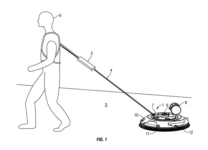
Figure 1 is a diagrammatic representation of a vacuum anchor
according to an embodiment of the invention connected to a worker
via a fall protection system;
Figure 2a shows the vacuum anchor of Figure 1 with the gas
container connected to the anchor body;
Figure 2b shows the vacuum anchor of figure 1 with the gas
container disconnected from the anchor body; and
Figure 3 shows a vacuum anchor according to an alternative
embodiment invention.
Referring to Figure 1, a vacuum anchor 1 secures to a surface 3, which may for
example be
an aircraft wing, to provide a fixed anchor point to which a safety lanyard 4
of a fall
protection system is connected. The lanyard 4 and associated shock pack 5 are
connected
to the anchor 1 and configured to arrest the fall of a person 6 to which they
are connected.
The lanyard 4 connects to a lanyard attachment point 7 on the anchor 1 by
means of a
karabina or similar lockable connection.
The anchor 1 includes a pressured gas container 8 which is connected by a gas
supply pipe
(not shown) to a gas inlet 9 provided on the substantially cylindrical anchor
body 10. The
pressurised gas from the gas container 8 is directed via the inlet 9 to a
venturi housed
within the anchor body 10. The venturi is in fluid connection with the base 11
of the
anchor body 10, which is circumferentially surrounded at its periphery by a
seal 12.
Pressurised gas moving at high velocity through the venturi causes a pressure
drop creating
a vacuum at the base 11. The seal 12 surrounding the base 11 maintains the
vacuum within
the base 11, with the resulting suction drawing the base 11 against the
surface 3 to anchor
the body 10 against the surface 3.
WO 2011/135363 PCT/GB2011/050837
-6-
A check valve may be provided within the anchor body 10, arranged to maintain
the
vacuum once it is created. A further release valve may also be provided to
release the
vacuum on demand. The venturi, gas pressure and anchor body size are selected
to ensure
that the vacuum suction generated is sufficient to withstand the impulse force
generated by
the arrest of a falling person by the fall protection system.
As shown in figure 2a, the lanyard attachment point 7 comprises an aperture
formed within
an attachment plate 14 configured to receive a lanyard connector. The
attachment plate 14
is rotationally mounted to the anchor body 10 about a rotational axis 15.
The gas container 8 is releasably held within a container clamp 16, and may be
removed
therefrom to allow the canister to be replaced, or for the pressurised gas
supply to be
replenished. The container clamp 16 is connected to a mounting bracket 17
which mounts
the gas container 8 to the attachment plate 14 on the opposing side of the
rotational axis to
the lanyard connection point 7. When connected to the attachment plate 14, as
shown in
figure 2a, the gas container 8 is rotatable with the attachment plate 14,
about the axis of
rotation 15.
The attachment plate 14 includes a connection lug 18 which extends
horizontally away
from the rotational axis 15 of the opposing side of the rotational axis 15
from the lanyard
connection 7. The container mounting bracket 17 includes a connection recess
19
configured to lockingly receive the connection lug 18. The connection recess
19 includes
wing connectors 20 which pivot on insertion of the lug 18, and engage with
corresponding
recesses inside of the lug 18, and which may be compressed to release the gas
container 8.
A connection pipe (not shown) is connected to the outlet 21 of the gas
container 8, and
extends and connects to the gas inlet 9 of the anchor body 10. The gas inlet 9
is rigidly
connected to the anchor body 10 such that the two are rotationally fixed
relative to each
other. A bearing is provided about the gas inlet 9 on which the attachment
plate 14 is
rotationally mounted.
WO 2011/135363 PCT/GB2011/050837
-7-
The gas connector pipe and gas inlet 9 are configured for relative rotation,
while
maintaining a gas tight seal therebetween. In use, as the worker 6 connected
to the anchor
body manoeuvres about the surface 3, the lanyard 4 pulls on the attachment
plate 14 at the
inlet connection point 7 causing rotation of the attachment plate 14 and the
gas container 8
about the rotational axis 15. As the gas connector and the gas inlet 9 are
configured for
relative rotation, when the gas container 8 rotates about the gas inlet 9 the
gas connector
rotates relative to the gas inlet 9 to enable continued free rotation of the
gas container 8 and
which prevents tangling or pulling of the gas connector.
In a further embodiment of the invention as shown in Figure 3, the gas
container 108 is
provided with an outlet port arrangement 130. The outlet port arrangement 130
includes a
clamp section 131 which secures to the outer surface of the gas container 108.
An outlet
valve connector 132 connects to the outlet 121 of the gas container 108 and
directs gas via
the supply tube 133 to the outlet port 134. The distal end of the outlet port
134 is
configured for connection with the gas inlet 109 of the anchor body 110. The
distal
connection 135 between the outlet port 134 and the gas inlet 109 is configured
as a push-fit
arrangement, such that when pushed onto the gas inlet 109 the outlet port 134
forms a gas
tight and rotatable connection with the gas inlet 109.
The gas container 108 further includes a connection lug 140 which projects
downwards
from the clamp member 131. A mounting plate 141 is fixed to the upper surface
of the
attachment plate 114, which is rotationally mounted about the gas inlet 109 as
described in
the previous embodiment. The mounting plate 141 includes a locking aperture
142
configured to receive the connection lug 140 to removably lock the gas
container to the
anchor body 110. The lateral spacing between the distal end of the outlet port
134 and the
connection lug 140 is equal to the lateral distance between the gas inlet 109
and the locking
aperture 142. In addition, the length of the outlet port 134 and the
connection lug 140 are
selected such that when the connection lug 140 is inserted into the connection
aperture
142, the distal connector 135 of the outlet port 134 simultaneously connects
with the gas
inlet 109.
WO 2011/135363 PCT/GB2011/050837
-8-
Furthermore, when the connection lug 140 is removed from the locking aperture
142 by
depression of a release button or similar, and the gas container 108 is pulled
upwardly, the
lug 140 and outlet port 134 are simultaneously disconnected from the locking
aperture 142
and gas inlet 109 respectively. As such, the gas container 108 may be quickly
and easily
rotatably connected to the anchor body 110, and similarly may be quickly and
easily
removed.
The gas outlet 134 is preferably a rigid cylindrical member arranged to extend
downwardly
from the gas container 108 in a direction perpendicular to the longitudinal
axis of the gas
container 108. As such, the rigid nature of the outlet port 134 enables the
gas container
108 to be at least partially supported on the anchor body 110 by the outlet
port 134.
Furthermore, as the outlet port 134 extends perpendicularly to the
longitudinal axis of the
gas container 108, the gas container 108 may be arranged horizontally relative
to the upper
surface of the anchor body 110 to limit its vertical profile, as opposed for
example to
extending vertically upwards, which increases the risk of the container 108
being knocked
or accidentally disconnected from the anchor body 110.
The mounting plate 142 is preferably connected to the attachment plate 114 on
the same
side of the rotational axis 115 as the lanyard connection point 107. As such,
the weight of
the container is distributed close to the lanyard connection point 107, to
enable smoother
rotation of the attachment plate about the rotational axis point 115.
It will be appreciated that in further embodiments various modifications to
the specific
arrangements described above and shown in the drawings may be made. For
example,
while the vacuum system is described as being provided by a venturi
arrangement, such is
not essential, and any means for creating a vacuum using a pressurised gas
supply may be
utilised. Furthermore, while the invention is described for use with an
aircraft wing, this is
not essential and the invention may be applied to any suitable surface with
which a vacuum
seal may be created.