Note: Descriptions are shown in the official language in which they were submitted.
CA 02794777 2012-09-27
WO 2011/134610 PCT/EP2011/001949
DESCRIPTION
A PROGRAMMABLE CYLINDER LOCK HAVING
A DEVICE FOR PROTECTION OF THE CODIFICATION,
AND THE KEYS FOR THE OPERATION THEREOF
BACKGROUND OF THE INVENTION
The subject of this invention is a programmable cylinder lock, namely
a lock comprising devices intended to allow the initial codification of the
lock
or, through a change operation, to modify the former lock codification in
order
to adjust the lock for being operated by a key different from the key to which
the lock was formerly adapted.
This invention also concerns the use keys and the change keys having
special characteristics in order to operating this lock. More particularly,
the
invention concerns improvements in a kind of programmable cylinder lock
which is known from the EP 0.226.252 and EP 0.900.310. Also the documents
US 2009/277239 and US 2005/217330 are of interest.
In a usual cylinder lock, which comprises a stator and a cylindrical ro-
tor mounted inside the stator, rotatable around its own axis and having a key-
hole extending along the direction of the axis for insertion of a key, a
number
of locking pins is mounted in the rotor, movable perpendicularly to the axis
on
the extension of the keyhole plane, and each locking pin is intended to coop-
erate with a section of the key, whose codification is represented by the
level
of a tooth or recess of the key which is situated in the considered key
section.
The length of each locking pin is such that, when it cooperates with the corre-
sponding section of the correct key-, its distal end portion corresponds to
the
cylindrical rotor surface and does not hinder its rotation, whereby, when all
the
locking pins are displaced in their respective correct positions by the
correct
key, the rotor can be rotated for operating the lock. When, on the contrary,
one or more locking pins are not in their correct positions, they (or
counterpins
which may be provided in the stator) extend through the cylindrical rotor sur-
face and hinder the rotation thereof and therefore the operation of the lock.
Because the lock codification is represented by the lengths of the locking
pins,
CA 02794777 2012 09 27
WO 2011/134610 PCT/EP2011/001949
2
and is established during the manufacture, the lock can be operated by only
one correct key, and it cannot be programmed.
The programmable locks of the kind to which applies the present in-
vention and which are described in the cited documents comprise, within a
rotor rotatably mounted inside the stator, instead of locking pins having
preestablished lengths, a number of key followers movable along their longitu-
dinal and transversal directions, intended to cooperate with the codification
conformations of a key inserted into the rotor keyhole, and locking pins
having
longitudinal movability which are the blocking members of the lock. The key
followers and the locking pins form pairs each comprising a locking pin and a
key follower, and the locking pins and key followers are provided with tooth-
ings intended to mutually cooperate, in different relative positions, for
deter-
mining the lock codification. A transversally displaceable stop bar, cooperat-
ing with a longitudinal stator groove and having projections suitable for coop-
erating with recesses of the locking pins, is intended to immobilize the
locking
pins when the rotor is rotated within the stator and, as a consequence, the
stop bar comes out of said groove and engages the locking pins. A transver-
sally displaceable change bar is slidably engaged with the key followers and
normally retains the same engaged with the locking pins, but this change bar,
when it enters said stator groove, transversally displaces the key followers
by
disengaging the same from the locking pins, thus allowing the modification of
the lock codification by replacing the former key by a new different key.
In a lock of this kind, during the rotation of the rotor for operating the
lock, the rotor passes through the change position, and then the key followers
are momentarily disengaged from the locking pins. If, though not being de-
sired a change, in this position the key is extracted or displaced, the lock
codification is lost or modified. For this reason there are known different
pro-
tection systems intended to hinder the extraction or the displacement of the
key when a change is not required. However, in the change position of the
rotor the engagement between the key followers and the locking pins is miss-
ing and therefore, even in the presence of such protection systems, the lock
codification might be modified or adulterated by rendering the same less pre-
cise, by accidental causes, such as clearances, a key wear or other grounds.
Therefore, the known protection systems are not entirely effective.
CA 02794777 2015-07-03
3
SUMMARY OF THE INVENTION
The main object of this invention is to improve a lock of the considered kind
in order to make up for the stated drawback, by preventing in a certain manner
any
modification of the lock codification when the rotor is situated in the change
position, in the case that the change operation is not deliberately required
by the
user.
The idea on which is based the invention is to prevent the disengagement
between key followers and locking pins in the change position, when the lock
is
operated by a normal use key and not by a special change key.
According to the present invention, there is provided a system including a
programmable cylinder lock and keys therefor, the programmable cylinder lock
comprising:
a stator;
a cylindrical rotor mounted inside the stator for rotation about an axis, said
rotor having a keyhole extending along the axis for insertion of a key;
a plurality of key followers inside said rotor, movable along longitudinal and
transverse directions, configured to cooperate with codification
conformations of a key inserted into the keyhole of said rotor; and
a plurality of locking pins inside said rotor, movable along a longitudinal
direction of the locking pins, which form lock blocking members;
wherein said key followers and said locking pins have teeth and form
together a plurality of pairs each including a locking pin and a key
follower that are configured to mutually cooperate, in different relative
positions, in order to define a lock codification,
the rotor further comprising:
a transversely displaceable stop bar configured to cooperate with a
longitudinal groove of said stator and configured to, when said rotor
rotates within said stator, come out of said groove and engage and
immobilize said locking pins; and
CA 02794777 2015-07-03
3a
a change bar that is transversely displaceable and is slidingly coupled with
said key followers to keep the key followers engaged with the locking
pins when said change bar is not in said groove of the stator, and to
disengage the key followers from the locking pins when said change bar
takes a lock programming position by entering said groove of the stator;
wherein at least one of the key followers comprises a projection opposite
the change bar, configured to engage a side surface of a key and, upon
contact of a normal use key with a side surface situated in a determined
position, to prevent transverse displacement of the key follower and the
change bar, and thereby to prevent disengagement of the key followers
from the locking pins, and
wherein said projection, upon contact of a special change key with a
corresponding side surface situated in a different position, is configured
to allow transverse displacement of the key follower and the change bar,
and thereby to allow disengagement of all key followers from the locking
pins of the lock.
Preferably, this object is attained, according to the invention, in a lock of
the stated kind, in that at least one of the key followers is provided, on the
side
opposed to the change bar, with a projection which engages a side surface of
the
key, and which prevents the transversal displacement of the key follower and
of the
change bar when the projection contacts a normal use key having its side
surface
situated in a determined position, whereas said projection, when contacting a
special change key having its side surface situated in a position different,
allows
the transversal displacement of the key follower and of the change bar, and
therefore the disengagement between all the key followers and locking pins of
the
lock.
Preferably, in this way, the protection against the displacement or
extraction of the use key in the change position is obtained as in the known
systems, but in addition there is also prevented any accidental modification
or
alteration of the lock codification when the rotor, operated by a use key,
passes
through the change position.
CA 02794777 2015-07-03
3b
Preferably, for reasons of resistance and of constructive unification, said
projection is provided on a number of key followers or, more preferably, on
all the
key followers of the lock.
Preferably, the use keys and the change keys intended to operate the lock
according to the invention are characterized in that they have a side surface
located in different positions for the use keys and for the change keys.
In a preferred embodiment, said different positions of a side surface of the
use keys and the change keys is obtained by giving to a key portion a
thickness
which differs between the use keys and the change keys.
CA 02794777 2012 09 27
WO 2011/134610 PCT/EP2011/001949
4
BRIEF DESCRIPTION OF THE DRAWINGS
These and other features, objects and advantages of the subject of
the present invention will more clearly appear from the following descrip-
tion of a preferred embodiment, being a not limiting example, with refer-
ence to the accompanying drawings, wherein:
Figure 1 represents, for the purpose of reference, a cross section of a
programmable cylinder lock known from the European Patent No. 0.900.310,
shown in a condition of normal operation.
Figure 2 shows a cross section corresponding to that of Figure 1, but
the lock being in a change condition.
Figure 3 shows a cross section of a lock according to the invention, in
a condition corresponding to that of Figure 2.
Figure 4 shows a cross section corresponding to that of Figure 3, but
in a special lock condition obtained thanks to the application of the
invention.
Figure 5 shows a use key suitable for being used with the lock ac-
cording to the invention.
Figure 6 shows on a larger scale a cross section of the use key, taken
along line VI-VI of Figure 5.
Figure 7 shows a change key suitable for being used with the lock ac-
cording to the invention.
Figure 8 shows on a larger scale a cross section of the change key,
taken along line VIII-VIII of Figure 7.
DESCRIPTION OF THE PREFERRED EMBODIMENTS
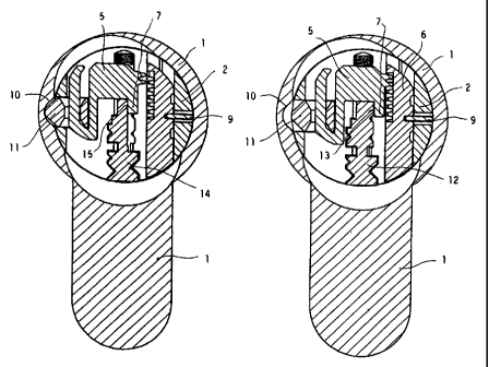
At first, reference to Figures 1 and 2 will be made in order to recall the
general structure and the operation of a lock of the considered kind, for
whose
particulars reference is made to the cited documents.
Number 1 designates a stator inside which there is rotatably mounted a
cylindrical rotor 2 having an axial keyhole susceptible of receiving a key 3.
In
the following, it will be considered as longitudinal the direction parallel to
the
axis of rotor 2 and the plane of the keyhole, and will be considered as
transver-
sal the direction perpendicular to the plane of the key and of the keyhole.
CA 02794777 2012 09 27
WO 2011/134610 PCT/EP2011/001949
In rotor 2 there are mounted key followers 4, which lie in a plane per-
pendicular to the axis of the cylindrical rotor 2 and are movable along the
lon-
gitudinal and transversal directions. The key followers 4 are provided for co-
operating with the codification conformations of key 3. Moreover, in rotor 2
5 there are mounted locking pins 6, and each of them is coplanar with a key
fol-
lower 4 and is movable along its own longitudinal direction. In the
represented
case the locking pins 6 cooperate with counterpins 8, and along with them they
form the blocking members of the lock.
The key followers 4 and the locking pins 6 have toothings intended to
mutually cooperate, and this cooperation may take place in different relative
positions in order to define the lock codification. A stop bar 9, displaceable
in
the transversal direction within rotor 2 and susceptible of cooperating with a
groove 10 of stator 1, serves for immobilizing the locking pins 6 when rotor 2
is made to rotate within stator 1 and, as a consequence, the stop bar 9 comes
out of said groove 10 and engages the locking pins 6.
A change bar 11 which is transversally displaceable in rotor .2 is slid-
ingly coupled with the key followers 4, and normally the change bar 11 keeps
the key followers 4 engaged with the locking pins 6 as shown by Figure 1 but,
when said change bar 11, due to a rotation of rotor 2, comes to correspond to
said groove 10 of stator 1 and enters therein, it transversally displaces the
key
followers 4 and disengages the same from the locking pins 6, as shown by
Figure 2. Then, by means of the replacement of the former key 3 by a differ-
ent key, it is possible to modify the lock codification.
The condition represented in Figure 2 takes place, in the known locks,
not only when a codification change is required, but every time the rotor 2,
during its rotation, passes through the position in which the change bar 11
cor-
responds to the groove 10 of stator 1 and penetrates therein. As a conse-
quence of this fact there are encountered the above cited drawbacks.
In Figures 3 and 4, which refer to the lock according to the invention,
the component parts corresponding to those of Figures 1 and 2 are designated
by the same references, and they will not be further described. In what con-
cerns the normal operation, out of the change position, the lock according to
the invention does in no way differ from the known locks.
The main difference of the lock according to Figures 3 and 4 with re-
spect to the known lock according to Figures 1 and 2 is that the key
followers,
CA 02794777 2012 09 27
WO 2011/134610 PCT/EP2011/001949
6
here designated by the reference 5, are provided on the side opposite the
change bar 11 with a projection 7. This projection 7 engages the side of key
12 or 14 inserted into the lock.
The use key 12 represented in Figures 5 and 6, when it is inserted in
the lock, has the outer surface 13 of one of its sections contacting the
projec-
tion 7 of the key follower 5, and this outer surface 13 of the use key 12 has
such a position that, due to the rest of projection 7 against the surface 13
of
key 12, the key follower 5 cannot displace in the transversal direction and,
therefore, it also retains the change bar 11. Therefore this latter, even when
it
is placed in correspondence of groove 10, cannot enter therein.
As shown by Figure 4, the key follower 5 remains engaged with the
locking pin 6, and in the same manner all the key followers 5 of the lock
remain
engaged with the corresponding locking pins 6. The codification of the lock
cannot be in any way altered. At the same time, the engagement of the key fol-
lowers 5 with the locking pins 6 prevents the key followers 5 from displacing
in
the longitudinal direction, so that the use key 12 cannot be extracted nor dis-
placed. Therefore, the change protection is obtained in a complete manner.
On the contrary the change key 14, represented in Figures 7 and 8,
has an outer surface 15 (corresponding to the outer surface 13 of the use key
12) located in a retracted position with respect to the position of the outer
surface 13 of the use key. For example, as in the embodiment shown, this is
due to a portion of the change key 14 having a thickness lower than the thick-
ness of the corresponding portion of the use key 12. Therefore the key fol-
lower 5 is free to displace in the transversal direction and does not ,retain
the
change bar 11. This latter, therefore, when it is located in correspondence
with groove 10, enters therein. As shown by Figure 3, the key follower 6 dis-
engages from the locking pin 6 and, in the same manner, all the key followers
5 of the lock disengage from the corresponding locking pins 6. The former
codification of the lock is thus deleted. At the same time, the disengagement
of the key followers 5 from the locking pins 6 allows the key followers 5 to
dis-
place in the longitudinal direction, whereby the change key may be extracted
and replaced by a different change key in order to codify the lock in a manner
different from the former one.
Thanks to the application of the invention there is obtained by simple
and sure means a complete safety of the precise retainment of the codification
CA 02794777 2015-07-03
7
as long as the lock is operated by use keys only, and this also in the case of
a
wrong maneuver of the user or in the presence of any accidental action,
whereas
the modification of the codification is very easy by using change keys.
It is easily understood that, in order to attain the behavior foreseen by the
invention, it is sufficient that a single key follower of the lock has the
described
features.
However it is preferred that a number of key followers, or more
preferably all the key followers of the lock, are provided with the described
features.
The characteristics of the invention may be applied to the locks of the
stated kind, irrespective of the fact that they foresee or not the presence of
master
keys.
It is to be understood that this invention is not limited to the embodiment
described and shown as an example. Several possible modifications have been
pointed out in the course of the description, and others are within the
ability of
those skilled in the art. These modification and others, and any replacement
by
technically equivalent means, can be made to what has been described and
shown.