Note: Descriptions are shown in the official language in which they were submitted.
CA 02794791 2012-11-06
. .
INTEGRATIVE ATRIAL FIBRILLATION ABLATION
BACKGROUND OF THE INVENTION
1. Field of the Invention.
[0001] This invention relates to relates generally to
minimally invasive treatment of organs inside the body. More
particularly, this invention relates to determination of abla-
tion sites for ablation treatments applied to cardiac tissue.
2. Description of the Related Art.
[0002] The meanings of certain acronyms and
abbreviations used herein are given in Table 1.
Table 1 - Acronyms and Abbreviations
AF Atrial Fibrillation
CFAE Complex Fractionated Atrial Electrogram
DF Dominant Frequency
GP Ganglionated Plexi
LA Left Atrium
MIBG 1231 -metaiodobenzylguanidine
MRI Magnetic Resonance Imaging
SPECT Single Photon Emission Computed Tomography
[0003] Cardiac arrhythmias, such as atrial fibrilla-
tion, occur when regions of cardiac tissue abnormally conduct
electric signals to adjacent tissue, thereby disrupting the
normal cardiac cycle and causing asynchronous rhythm.
[0004] Procedures for treating arrhythmia include sur-
gically disrupting the origin of the signals causing the ar-
rhythmia, as well as disrupting the conducting pathway for such
signals. By selectively ablating cardiac tissue by application
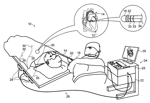
of energy via a catheter, it is sometimes possible to cease or
modify the propagation of unwanted electrical signals from one
portion of the heart to another. The ablation process destroys
the unwanted electrical pathways by formation of non-conducting
lesions.
1 of 22
CA 02794791 2012-11-06
[0005] Successful catheter-based ablation for atrial
fibrillation (AF) often entails accurate execution of a rela-
tively complex therapeutic plan comprising many ablation
points. The procedure is challenging and time consuming. For
example, in the document A New Approach for Catheter Ablation
of Atrial Fibrillation: Mapping of the Electrophysiologic
Substrate, Nademanee et a/., J. Am. Coll. Cardiol., 2004;
43(11): 2044-2053, it was proposed that atrial fibrillation may
be treated by ablating sites exhibiting a complex fractionated
atrial electrogram (CFAE). The authors identified areas of CFAE
during atrial fibrillation, and then applied radiofrequency ab-
lation to these areas. As a result of the ablation, the atrial
fibrillation was resolved in the large majority of the cases.
[0006] Nademanee's method requires a human operator to
read electrograms to identify sites of CFAE. Commonly assigned
U.S. Patent Application Publication No. 2007/0197929, which is
herein incorporated by reference, facilitates the procedure by
disclosing automated detection and mapping of areas of complex
fractionated electrograms within cardiac chambers. Commonly as-
signed U.S. Patent Application Publication No. 20090192393,
which is herein incorporated by reference, discloses automatic
detection and mapping of ganglionated plexi that are found
within areas of complex fractionated electrograms in cardiac
chambers. Functional maps indicating a spatial distribution of
the ganglionated plexi and the relative numbers of complex
fractionated electrograms are produced for display.
[0007] More recently, SPECT and planar cardiac sympa-
thetic imaging using 123 I-metaiodobenzylguanidine (MIBG) has be-
come sufficiently well known to indicate standardization, as
described by Albert Flotats et a/., Proposal for
standardization of 123I-metaiodobenzylguanidine (MIBG) cardiac
sympathetic imaging by the EANM Cardiovascular Committee and
the European Council of Nuclear Cardiology, Eur J Nucl Med Mol
2 of 22
CA 02794791 2012-11-06
Imaging (2010) 37:1802-1812. Techniques disclosed in Rozovsky
et al., Added Value of SPECT/CT for Correlation of MIBG
Scintigraphy and Diagnostic CT in Neuroblastoma and
Pheochromooytoma, AJR 2008; 190:1085-1090 may be adapted for
imaging ganglionated plexi in the heart.
[0008] Evaluation of epicardial fat may also be useful
in identifying ablation points. For example, commonly assigned
U.S. Patent Application Publication No. 2008/0058657, which is
herein incorporated by reference, describes obtaining an endo-
cardial map by constructing a matrix relationship between a
small number of endocardial points and a large number of exter-
nal receiving points using a multi-electrode chest panel. Mag-
netic resonance imaging (MRI) and computed tomography have also
been applied to the evaluation of epicardial fat, as described
for example in Abbara et al., Mapping Epicardial Fat With
Multi-Detector Computed Tomography To Facilitate Percutaneous
Transepicardial Arrhythmia Ablation, European Journal of
Radiology 57 (2006) 417-422, and in Kriegshauser et al., MR
Imaging of Fat in and Around the Heart, AJR 155:271-274,
August 1990.
[0009] It has been noted in Dewire, J. & Calkins,
State-of-the-art and Emerging Technologies for Atrial
Fibrillation Ablation, H. Nat. Rev. Cardiol. 7, 129-138 (2010)
that there is an interest in the development of new tools and
strategies that will improve the safety and efficacy of AF ab-
lation, shorten procedure time, and allow ablation to be per-
formed by operators with little prior experience of the tech-
nique.
SUMMARY OF THE INVENTION
[0010] There is provided according to embodiments of
the invention a method of ablation, which is carried out by de-
fining first regions containing first locations including gan-
glionated plexi in a heart of a living subject, and inserting a
3 of 22
CA 02794791 2012-11-06
probe into the heart, the probe having electrodes on a distal
portion thereof. The method is further carried out by detecting
electrical activity in the heart via the electrodes, defining
second regions having second locations, wherein the electrical
activity exhibits a dominant frequency that is higher than a
predefined threshold, defining third regions having third loca-
tions, wherein the electrical activity exhibits complex frac-
tionated atrial electrograms, constructing an electroanatomical
map of the heart that defines intersections of the first re-
gions and at least one of the second regions and the third re-
gions, selecting ablation sites within the intersections, and
ablating cardiac tissue at the ablation sites.
[0011] An aspect of the method includes defining
fourth regions, wherein a contact pressure between the probe
and a wall of the heart exceeds a predefined pressure thresh-
old, and wherein the intersections defined in the electro-
anatomical map comprise intersections of the first regions, the
second regions, the third regions and the fourth regions.
[0012] According to another aspect of the method, de-
fining first regions includes electrically stimulating the
heart at a stimulation frequency that exceeds a stimulation
threshold.
[0013] According to one aspect of the method, defining
first regions comprises evaluating epicardial fat pads of the
heart.
[0014] According to a further aspect of the method,
defining first regions is performed by at least one of sympa-
thetic cardiac imaging, magnetic resonance imaging, computed
tomographic imaging and multi-detector computed tomography.
[0015] According to another aspect of the method, the
first regions, the second regions and the third regions are 3-
dimensional, and wherein constructing an electroanatomical map
4 of 22
CA 02794791 2012-11-06
includes displaying the electroanatomical map as at least one
2-dimensional projection.
[0016] According to yet another aspect of the method,
constructing an electroanatomical map includes defining inter-
sections of the first regions, the second regions and the third
regions.
[0017] Still another aspect of the method includes de-
fining segments of the heart, wherein defining first regions,
defining second regions, defining third regions, and selecting
ablation sites are performed separately for each of the seg-
ments.
[0018] According to an additional aspect of the
method, selecting ablation sites is performed by random selec-
tion within the intersections.
[0019] According to one aspect of the method, select-
ing ablation sites is performed by choosing ones of the second
locations and the third locations within the intersections.
[0020] Other embodiments of the invention provide ap-
paratus for carrying out the above-described method.
BRIEF DESCRIPTION OF THE SEVERAL VIEWS OF THE DRAWINGS
[0021] For a better understanding of the present inven-
tion, reference is made to the detailed description of the in-
vention, by way of example, which is to be read in conjunction
with the following drawings, wherein like elements are given
like reference numerals, and wherein:
[0022] Fig. 1 is a pictorial illustration of a sys-
tem for performing ablative procedures on a heart of a living
subject, which is constructed and operative in accordance with
an embodiment of the invention;
[0023] Fig. 2 is a series of diagrams based on data
collected from a series of patients who underwent cardiac cath-
5 of 22
, CA 02794791 2012-11-06
eterization that illustrates selection of ablation sites in ac-
cordance with an embodiment of the invention;
[0024] Fig. 3 is a flow chart of a method of integrat-
ing data collected using a plurality of methods to select abla-
tion points for treatment of atrial fibrillation and other car-
diac arrhythmias in accordance with an embodiment of the inven-
tion;
[0025] Fig. 4 illustrates importation and registration
of pre-acquired images into an electroanatomical map in accor-
dance with an embodiment of the invention;
[0026] Fig. 5 is a portion of the flow chart shown in
Fig. 3, which has been modified in accordance with an alternate
embodiment of the invention; and
[0027] Fig. 6 is a portion of the flow chart shown in
Fig. 3, which has been modified in accordance with another al-
ternate embodiment of the invention.
DETAILED DESCRIPTION OF THE INVENTION
[0028] In the following description, numerous specific
details are set forth in order to provide a thorough under-
standing of the various principles of the present invention. It
will be apparent to one skilled in the art, however, that not
all these details are necessarily always needed for practicing
the present invention. In this instance, well-known circuits,
control logic, and the details of computer program instructions
for conventional algorithms and processes have not been shown
in detail in order not to obscure the general concepts unneces-
sarily.
[0029] Aspects of the present invention may be embodied
in software programming code, which is typically maintained in
permanent storage, such as a computer readable medium. In a
client/server environment, such software programming code may
be stored on a client or a server. The software programming
6 of 22
CA 02794791 2012-11-06
code may be embodied on any of a variety of known non-
transitory media for use with a data processing system, such as
a diskette, hard drive, electronic media or CD-ROM. The code
may be distributed on such media, or may be distributed to us-
ers from the memory or storage of one computer system over a
network of some type to storage devices on other computer sys-
tems for use by users of such other systems.
[0030] Turning now to the drawings, reference is ini-
tially made to Fig. 1, which is a pictorial illustration of a
system 10 for performing ablative procedures on a heart 12 of a
living subject, which is constructed and operative in accor-
dance with a disclosed embodiment of the invention. The system
comprises a catheter 14, which is percutaneously inserted by an
operator 16 through the patient's vascular system into a cham-
ber or vascular structure of the heart 12. An operator 16, who
is typically a physician, brings the catheter's distal tip 18
into contact with the heart wall. Electrical activation maps
may then be prepared, according to the methods disclosed in
U.S. Patent Nos. 6,226,542, and 6,301,496, and in commonly as-
signed U.S. Patent No. 6,892,091, whose disclosures are herein
incorporated by reference. One commercial product embodying el-
ements of the system 10 is available as the CARTO(D, 3 System,
available from Biosense Webster, Inc., 3333 Diamond Canyon
Road, Diamond Bar, CA 91765.
[0031] Areas determined to be abnormal, for example by
evaluation of the electrical activation maps, can be ablated by
application of thermal energy, e.g., by passage of radiofre-
quency electrical current through wires in the catheter to one
or more electrodes at the distal tip 18, which apply the ra-
diofrequency energy to the myocardium. The energy is absorbed
in the tissue, heating it to a point (typically about 50 C) at
which it permanently loses its electrical excitability. When
successful, this procedure creates non-conducting lesions in
7 of 22
CA 02794791 2012-11-06
the cardiac tissue, which disrupt the abnormal electrical path-
way causing the arrhythmia. The principles of the invention can
be applied to different heart chambers to treat many different
cardiac arrhythmias.
[0032] The catheter 14 typically comprises a han-
dle 20, having suitable controls on the handle to enable the
operator 16 to steer, position and orient the distal end of the
catheter as desired for the ablation. To aid the operator 16,
the distal portion of the catheter 14 contains position sensors
(not shown) that provide signals to a positioning processor 22,
located in a console 24.
[0033] Ablation energy and electrical signals can be
conveyed to and from the heart 12 through one or more ablation
electrodes 32 located at or near the distal tip 18 via cable 34
to the console 24. Sensing electrodes 33, also connected to the
console 24 are disposed generally in the distal portion of the
catheter 14, and have connections to the cable 34. Pacing sig-
nals and various other signals may be conveyed from the con-
sole 24 through the cable 34 and the electrodes 32, 33 to and
from the heart 12. Many configurations of the electrodes 32, 33
are possible. For example the ablation electrode 32 may be dis-
posed at the distal tip 18.
[0034] Wire connections 35 link the console 24 with
body surface electrodes 30 and other components of a position-
ing sub-system. The ablation electrode 32, the sensing elec-
trodes 33 and the body surface electrodes 30 may be used to
measure tissue impedance at the ablation site as taught in U.S.
Patent No. 7,536,218, issued to Govari et al., which is herein
incorporated by reference. A temperature sensor (not shown),
typically a thermocouple or thermistor, may be mounted on or
near the ablation electrode 32. While shown as a ring electrode
in Fig. 1, the ablation electrode 32 may be a tip electrode.
8 of 22
CA 02794791 2012-11-06
, .
Optionally, more than one instance of the ablation electrode 32
may be mounted on the catheter 14.
[0035] The console 24 typically contains one or more
ablation power generators 25. The catheter 14 may be adapted to
conduct ablative energy to the heart using any known ablation
technique, e.g., radiofrequency energy, ultrasound energy, and
laser-produced light energy. Such methods are disclosed in com-
monly assigned U.S. Patent Nos. 6,814,733, 6,997,924,
and 7,156,816, which are herein incorporated by reference.
[0036] The positioning processor 22 is an element of a
positioning system 26 of the system 10 that measures location
and orientation coordinates of the catheter 14.
[0037] In one embodiment, the positioning system 26
comprises a magnetic position tracking arrangement that deter-
mines the position and orientation of the catheter 14 by gener-
ating magnetic fields in a predefined working volume its vicin-
ity and sensing these fields at the catheter using field gener-
ating coils 28 and may include impedance measurement, as
taught, for example in U.S. Patent Application Publication
No. 2007/0060832, which is herein incorporated by reference.
The positioning system 26 may be enhanced by position measure-
ments using the impedance measurements described in the above-
noted U.S. Patent No. 7,536,218.
[0038] As noted above, the catheter 14 is coupled to
the console 24, which enables the operator 16 to observe and
regulate the functions of the catheter 14. Console 24 includes
a processor, which can be a computer with appropriate signal
processing circuits. The processor is coupled to drive a moni-
tor 29. The signal processing circuits typically receive, am-
plify, filter and digitize signals from the catheter 14, in-
cluding signals generated by the above-noted sensors and a plu-
rality of location sensing electrodes (not shown) located dis-
tally in the catheter 14. The digitized signals are received
9 of 22
CA 02794791 2012-11-06
and used by the console 24 and the positioning system 26 to
compute the position and orientation of the catheter 14 and to
analyze the electrical signals from the electrodes.
[0039] Typically, the system 10 includes other ele-
ments, which are not shown in the figures for the sake of sim-
plicity. For example, the system 10 may include an electrocar-
diogram (ECG) monitor, coupled to receive signals from one or
more body surface electrodes, so as to provide an ECG synchro-
nization signal to the console 24. As mentioned above, the sys-
tern 10 typically also includes a reference position sensor, ei-
ther on an externally-applied reference patch attached to the
exterior of the subject's body, or on an internally-placed ca-
theter, which is inserted into the heart 12 maintained in a
fixed position relative to the heart 12. Conventional pumps and
lines for circulating liquids through the catheter 14 for cool-
ing the ablation site are provided.
[0040] Moreover, the system 10 has facilities for reg-
istering images produced by other modalities, e.g., the CT,
MRI, and nuclear images as described above with current and
previously generated electro-anatomic maps of the heart 12. The
CARTOMERGETM Image Integration Module, available from Biosense
Webster is suitable.
[0041] Reference is now made to Fig. 2, which is a se-
ries of diagrams based on data collected from a series of pa-
tients who underwent cardiac catheterization that illustrates
selection of ablation sites in accordance with an embodiment of
the invention. The diagrams represent mappings of a left atrium
in a right lateral view 37, right anterior oblique view 39
(PAD) and posterior-anterior view 43. As noted above, arrhyth-
mogenic zones are associated with areas containing ganglionated
plexi and with demonstrable complex fractionated atrial elec-
trograms. Moreover, frequency gradients are known to exist in
hearts exhibiting atrial fibrillation and can be identified by
10 of 22
CA 02794791 2012-11-06
electroanatomical mapping, for example, using the above-noted
CARTO 3 system. Ablation of sites having electrical activity
exhibiting high dominant frequencies (DF) that exceed a prede-
fined threshold often results in prolongation of cycle length
and termination of the arrhythmia. The threshold criteria ap-
plied to power spectra of the electrograms that are described
in Sanders et al., Spectral Analysis Identifies Sites of High-
Frequency Activity Maintaining Atrial Fibrillation in Humans,
Circulation. 2005;112:789-797, herein incorporated by refer-
ence, are suitable for defining sites having high DF.
[0042] A key 45 at the right of the figure indicates
three features of the mappings that are taken into considera-
tion when ablation points are selected: Fig. 2 demonstrates re-
gions 47 containing CFAE, regions 49 containing dominant fre-
quency sites, and regions 51 containing ganglionated plexi. De-
finition of these regions is described below. Proposed ablation
points 53 are shown. The first, second and third regions are
actually 3-dimensional, but are shown in 2-dimensional projec-
tions in Fig. 2. Sites containing CFAE may be determined using
the techniques described in the above-noted U.S. Patent Appli-
cation Publication No. 20090192393. Sites having a dominant
frequency can be determined according to the teachings of com-
monly assigned U.S. Patent No. 7,907,994 to Stolarski, et a/.,
which is herein incorporated by reference. Alternatively, the
CARTO 3 system may be employed for electroanatomical mapping to
identify CFAE and dominant frequency sites, augmented by visu-
alization of ganglionated plexi using cardiac sympathetic imag-
ing with MIBG. The CARTO 3 system enables the MIBG images to be
placed in registration with the electroanatomical maps. How-
ever, these features may be located by any of the methods de-
scribed hereinabove and combinations thereof.
[0043] Reference is now made to Fig. 3, which is a
flow chart of a method of integrating data collected using a
11 of 22
CA 02794791 2012-11-06
plurality of modalities to optimally select ablation points for
treatment of atrial fibrillation and other cardiac arrhythmias
in accordance with an embodiment of the invention. The process
steps are shown in a particular linear sequence in Fig. 3 for
clarity of presentation. However, it will be evident that many
of them can be performed in parallel, asynchronously, or in
different orders. Moreover, not all illustrated process steps
may be required to implement the process.
[0044] In a first phase 55 cardiac data is acquired by
any combination of several modalities. Typically, but not nec-
essarily, first phase 55 occurs prior to cardiac catheteriza-
tion. The cardiac anatomy may be imaged by at least one of CT
and MRI methods at step 57. Evaluation of cardiac fat to locate
ganglionated plexi may be performed using the same or different
CT and/or MRI studies at step 59. MIBG imaging using hybrid CT
and single photon emission computed tomography (SPECT) may be
performed in step 61 in order to more precisely locate the gan-
glionated plexi.
[0045] In a second phase 63 the images acquired in the
first phase 55 are segmented, such that only the relevant ana-
tomical structures required for preplanning and execution of an
atrial fibrillation ablation are available in 3D and at high
resolution. The left atrium, pulmonary veins and epicardial fat
pads are defined as appropriate for the particular images ob-
tamed in first phase 55. Thus, in step 65, the left atrium,
pulmonary veins (PVs) and epicardial fat pads are defined in
the images acquired in step 59. In step 67, the left atrium,
pulmonary veins and ganglionated plexi are identified in the
MIBG images acquired in step 61. When epicardial fat pads are
analyzed, the ganglionated plexi locations are inferred. In
step 69 The left atrium and pulmonary veins are identified in
the images acquired in step 57.
12 of 22
CA 02794791 2012-11-06
, .
[0046] At step 71 the images processed in second
phase 63 are imported into an electro-anatomic mapping system,
e.g., the CARTO 3 system. Step 71 can be performed using the
above-noted CARTOMERGE image integration module.
[0047] Reference is now made to Fig. 4, which illus-
trates the importation and registration of pre-acquired images
into an electroanatomical map in accordance with an embodiment
of the invention. In a right anterior oblique view 73 (RAO
view), the right superior pulmonary vein (RSPV), right inferior
pulmonary vein (RIPV) and left atrium (LA) are defined. A re-
gion 75 containing the anterior right ganglionated plexus is
indicated. In a posterior-anterior (PA) view 77 the RSPV, RIPV,
left superior pulmonary vein (LSPV) and left inferior pulmonary
vein (LIPV) are shown. The view 77 further indicates the supe-
nor left, inferior right and inferior left ganglionated plexi
as regions 79, 81, 83, respectively. Circles 85 (Fig. 4) indi-
cate sites having a dominant frequency.
[0048] Reverting to Fig. 3, in a third phase 87 car-
diac catheterization is performed. Anatomic mapping of the left
atrium is performed in step 89. This may be accomplished using
the CARTO 3 system by transseptal and endocardial mapping. A
technique for transseptal mapping is described, for example, in
commonly assigned U.S. Patent No. 7,229,415 to Schwartz, which
is herein incorporated by reference. Optionally, step 89 may be
performed concurrently with realtime ultrasound imaging in
step 91, for example using an Ultra ICETm catheter, available
from Boston Scientific, One Boston Scientific Place, Natick, MA
01760-1537.
[0049] In step 93 electroanatomical mapping is per-
formed, typically concomitantly with step 89. Referring again
to Fig. 4, second regions containing dominant frequency sites
(circles 85) and third regions showing CFAE are mapped in
step 93, together with the ganglionated plexi-containing re-
13 of 22
CA 02794791 2012-11-06
gions 75, 79, 81, 83. CFAE-containing regions 95 are repre-
sented as areas on the map. However these areas are defined by
a number of discrete sampled points 97 on the endocardium in
which CFAE were demonstrated, as described in the above-noted
U.S. Patent Application Publication No. 2007/0197929.
[0050] In a fourth phase 99 (Fig. 3), the points and
regions developed and mapped in the third phase 87 are proc-
essed in order to select a set of ablation points. This is done
by identifying intersections of areas containing ganglionated
plexi, CFAE, and dominant frequency sites. In one method the
intersections are identified by moving a circular area 101 of
10 mm diameter about the electroanatomical map in discrete
steps. At each position of the circular area 101, points there-
in belonging to the relevant categories (referred to as "hits")
are identified. As noted above, the categories are ganglionated
plexi, points showing CFAE, and points of dominant frequency.
[0051] As best seen in the right lateral view 37 and
right anterior oblique view 39 (Fig. 2), points 103 lying in
the "intersection" of regions containing CFAE, dominant fre-
quency and ganglionated plexi (as determined by evaluation of
cardiac fat) are identified as candidates for selection as ab-
lation points. The pseudocode of Listing 1 presents one method
for making the determination:
Listing 1
For each segment of LA (as defined in second phase 63)
Position 10 mm circular window on map reconstruction in
current segment
Define first regions containing ganglionated plexi based
on expected anatomic locations (regions 51, Fig. 2);
Do
14 of 22
CA 02794791 2012-11-06
Record CFAE "hits" in window in First region
Record hits indicating dominant frequency site in
window
Move circular window to new position in segment
Loop until all first regions in current segment are
Evaluated
Define second regions containing dominant frequency sites
(regions 49, Fig. 2);
Define third regions containing CFAE (regions 47,
Fig. 2). Generally the regions are defined such that the
acquired points are relatively evenly distributed. This
reduces the sample size required to obtain meaningful
information. The above-noted CARTO 3system provides
operator-assisted facilities for defining endocardial
regions of enterest;
Identify first intersections of second regions (CFAE)
with third regions (DF) (step 105, Fig. 3).
Identify second intersections of the first intersections
and sites of ganglionated plexi by performing at least
one of steps 107, 109. (If one of the first regions and
second regions does not exist, then treat the other of
the first regions and second regions as the first
intersection.
Select at random N points in each of the second
intersections for ablation (final step 111). The selected
15 of 22
CA 02794791 2012-11-06
N points should coincide with the points corresponding to
the CFAE or DF hits.
Optionally, rank the areas covered by the moving windows
according to the number of hits, and limit the selection
of the N points in the preceding step to highly ranked
areas, disregarding the lower ranked areas. A cut-off may
be set by the operator, or chosen arbitrarily, for
example, the areas only in the highest quartile may be
subject to selection.
next segment.
[0052] In final step 111
ablation points are selected
from candidates within the intersections. The selection process
may be automatic, for example using the above-noted CARTO 3
system, or operator-assisted. The ablation points may be recom-
mended randomly within the intersections. Alternatively, the
ablation points may be selected by the operator from points
that were identified during the catheterization as exhibiting
both dominant frequency sites and CFAE.
[0053] Alternatively, rather
than segmenting the left
atrium, the hit-containing areas may be evaluated globally
within the left atrium. The chosen ablation points may be high-
lighted on a display for the operator. Ablation may then pro-
ceed at the chosen sites. In general, fewer than all the candi-
dates are selected as ablation points. This reduces operating
time and patient morbidity.
Alternate Embodiment 1.[0054]
With continued reference to Fig. 3, in this va-
riant, the mapping process described in the third phase 87 is
augmented by including a map of the contact force between the
16 of 22
CA 02794791 2012-11-06
. .
catheter and the endocardium during the electroanatomic mapping
process (step 89). The cardiac catheter incorporates a pressure
detector for sensing a mechanical force against the distal tip
when engaging an ablation site. A contact force catheter of the
sort described in commonly assigned U.S. Patent Application
Publication No. 2011/0152856, which is herein incorporated by
reference, may be used for this purpose. A suitable contact
force catheter is available from Biosense-Webster as the
THERMOCOOL0, SMARTTOUCHTM Contact Force Sensing Catheter. Re-
gions having points in which the contact force exceeds a thre-
shold value are defined (CF regions) In these regions only lo-
cal effects contribute are perceived in the sensor; far field
effects are filtered out. A contact force of at least 7g is
suggested.
(0055] Reference is now made to Fig. 5, which is a
portion of the flow chart shown in Fig. 3, and which has been
modified in accordance with an alternate embodiment of the in-
vention. After performing step 89 (Fig. 3), in step 113 elec-
troanatomical mapping is performed as in step 93 (Fig. 3), and
concomitantly with contact force mapping.
[0056] Next, step 115 is similar to step 105 (Fig. 3),
except intersections are determined between the second regions
(CFAE) with third regions (DF) and the CF regions. The proce-
dure then continues in the same manner as described above with
respect to Fig. 3. Limiting the selection of ablation points to
areas having sufficiently high contact force prevents far field
effects from interfering with the selection of ablation sites.
Alternate Embodiment 2.
[0057] Reference is now made to Fig. 6, which is a por-
tion of the flow chart shown in Fig. 3, and which has been mod-
ified in accordance with an alternate embodiment of the inven-
tion. In this embodiment, detection of ganglionated plexi is
enhanced during the mapping of CFAE and dominant frequency
17 of 22
CA 02794791 2012-11-06
sites as performed in step 93 (Fig. 3) by high frequency stimu-
lation at step 117. Stimulation at 20Hz, 12 Volts, with a pulse
width of 10 ms is suitable. Typically, the use of high fre-
quency stimulation is focused on areas in which ganglionated
plexi are anticipated, based on registration of images acquired
by the above-describe imaging techniques.
[0058] Step 117 defines first regions containing gan-
glionated plexi by the use of high frequency stimulation, sec-
ond regions containing CFAE and dominant frequency sites as de-
scribed above with reference to step 93 (Fig. 3).
[0059] Step 93 is performed to define first intersec-
tions of second regions (CFAE) with third regions (DF) as de-
scribed above with respect to Fig. 3. Step 119 is performed to
define second intersections of the first intersections and the
first regions containing ganglionated plexi as determined by
high frequency stimulation. The procedure then continues with
final step 111 as described with respect to Fig. 3.
[0060] It will be appreciated by persons skilled in
the art that the present invention is not limited to what has
been particularly shown and described hereinabove. Rather, the
scope of the present invention includes both combinations and
sub-combinations of the various features described hereinabove,
as well as variations and modifications thereof that are not in
the prior art, which would occur to persons skilled in the art
upon reading the foregoing description.
18 of 22