Note: Descriptions are shown in the official language in which they were submitted.
CA 2795233 2017-05-04
TITLE OF THE INVENTION
SYSTEMS AND METHODS FOR MEASURING REDUCED PRESSURE
EMPLOYING AN ISOLATED FLUID PATH
[0001]
15 BACKGROUND
[0002] The present disclosure relates generally to reduced-pressure medical
treatment
systems and, more particularly, but not by way of limitation, to systems and
methods for
measuring reduced pressure that employ an isolated fluid path.
[00031 Clinical studies and practice have shown that providing a reduced
pressure in
proximity to a tissue site augments and accelerates the growth of new tissue
at the tissue site.
The applications of this phenomenon are numerous, but application of reduced
pressure has
been particularly successful in treating wounds. This treatment (frequently
referred to in the
medical community as "negative pressure wound therapy," "reduced pressure
therapy," or
"vacuum therapy") provides a number of benefits, which may include faster
healing and
increased formulation of granulation tissue. Typically, reduced pressure is
applied to tissue
through a porous pad or other manifold device. The porous pad contains cells
or pores that are
capable of distributing reduced pressure to the tissue and channeling fluids
that are drawn
from the tissue. At times, it may be desirable to determine the reduced
pressure involved at
the tissue site. For example, it may be desirable to ascertain that the
reduced pressure is in a
therapeutic range.
1
CA 02795233 2012-10-01
WO 2011/146533 PCT/US2011/036879
SUMMARY
[0004] According an illustrative, non-limiting embodiment, a system for
treating a
tissue site on a patient with reduced pressure includes a treatment manifold
for deploying
proximate to the tissue site, a sealing member for forming a fluid seal over
the treatment
manifold and a portion of the patient's epidermis, a reduced-pressure source
for providing
reduced pressure, and a reduced-pressure delivery conduit for fluidly coupling
to the treatment
manifold and to the reduced-pressure source. The reduced-pressure delivery
conduit is for
delivering treatment-reduced-pressure to the treatment manifold. The system
further includes
a reduced-pressure assessment conduit for fluidly coupling to the tissue site
and an assessment
chamber. The assessment chamber is for fluidly coupling to the reduced-
pressure assessment
conduit and for receiving an assessment-reduced-pressure from the tissue site.
The assessment
chamber includes a sealed enclosure having a first moveable portion on a wall.
The first
moveable portion is operable to move under the influence of reduced pressure.
The system
also includes a first pressure detector proximate to the first moveable
portion of the assessment
chamber. The first pressure detector is fluidly isolated from the assessment
chamber and is
operable to sense displacement of the first moveable portion.
[0005] According to another illustrative, non-limiting embodiment, a method
for
treating a tissue site on a patient with reduced pressure includes disposing a
treatment
manifold proximate to the tissue site, disposing a sealing member over the
treatment manifold
and a portion of the patient's epidermis to form a fluid seal, providing a
reduced-pressure
source, fluidly coupling a reduced-pressure delivery conduit to the treatment
manifold and to
the reduced-pressure source, providing an assessment chamber, and fluidly
coupling a
reduced-pressure assessment conduit to the assessment chamber and to the
tissue site for
delivering an assessment-reduced-pressure to the assessment chamber. The
assessment
chamber has a first moveable portion on a wall. The method further includes
disposing a first
pressure detector proximate to the first moveable portion of the assessment
chamber. The first
pressure detector is fluidly isolated from the assessment chamber. The method
also includes
using the first pressure detector to sense displacement of the first moveable
portion.
[0006] According to another illustrative, non-limiting embodiment, a method
for
manufacturing a system for measuring reduced pressure at a tissue site on a
patient includes
forming an assessment chamber having a sealed enclosure with a first moveable
portion, and
2
CA 02795233 2012-10-01
WO 2011/146533 PCT/US2011/036879
forming a reduced-pressure assessment conduit having a distal end and a
proximal end. The
reduced-pressure assessment conduit is for fluidly coupling at the distal end
to the tissue site
and at the proximal end to the assessment chamber. The method also includes
forming a first
pressure detector disposed proximate to the first moveable portion of the
assessment chamber
and fluidly isolated from the assessment chamber. The first pressure detector
is operable to
sense displacement of the first moveable portion.
[0007] Other objects and advantages of the illustrative embodiments will
become
apparent with reference to the drawings and detailed description that follow.
BRIEF DESCRIPTION OF THE DRAWINGS
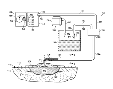
[0008] FIGURE 1 is a schematic diagram with a portion shown in cross section
of an
illustrative, non-limiting embodiment of a reduced-pressure treatment system
employing a
subsystem for measuring reduced pressure that includes a first pressure
detector isolated from
an assessment chamber;
[0009] FIGURE 2 is a cross section of an illustrative, non-limiting embodiment
of a
combination conduit taken along line 2-2 in FIGURE 1;
[0010] FIGURE 3 is a schematic diagram of an illustrative, non-limiting
embodiment
of a reduced-pressure therapy unit;
[0011] FIGURE 4A is a schematic diagram of an illustrative, non-limiting
embodiment
of a pressure detector utilizing an electromagnetic coil and placed proximate
to a first
diaphragm having ferrite;
[0012] FIGURE 4B is the pressure detector of FIGURE 4A shown with the first
diaphragm displaced;
[0013] FIGURE 5A is a schematic diagram of another illustrative, non-limiting
embodiment of a pressure detector utilizing a Hall Effect sensor and placed
proximate to a first
diaphragm, which has a permanent magnet;
[0014] FIGURE 5B is the pressure detector of FIGURE 5A shown with the first
diaphragm displaced;
[0015] FIGURE 6A is a schematic diagram of an illustrative, non-limiting
embodiment
of a pressure detector having a capacitive sensor proximate to a first
diaphragm, which has
ferrite;
3
CA 02795233 2012-10-01
WO 2011/146533 PCT/US2011/036879
[0016] FIGURE 6B is the pressure indicator of FIGURE 6A shown with the first
diaphragm displaced;
[0017] FIGURE 7A is a schematic diagram of an illustrative, non-limiting
embodiment
of a pressure detector that includes an ultrasonic sensor and placed proximate
to a first
diaphragm;
[0018] FIGURE 7B is the pressure detector of FIGURE 7A shown with the first
diaphragm displaced;
[0019] FIGURE 8A is a schematic diagram of an illustrative, non-limiting
embodiment
of a pressure detector including an infrared sensor and placed proximate to a
first diaphragm,
which has a reflector; and
[0020] FIGURE 8B is the pressure detector of FIGURE 8A shown with the first
diaphragm displaced.
4
CA 02795233 2012-10-01
WO 2011/146533 PCT/US2011/036879
DETAILED DESCRIPTION OF ILLUSTRATIVE EMBODIMENTS
[0021] In the following detailed description of the illustrative embodiments,
reference
is made to the accompanying drawings that form a part hereof These embodiments
are
described in sufficient detail to enable those skilled in the art to practice
the invention, and it is
understood that other embodiments may be utilized and that logical structural,
mechanical,
electrical, and chemical changes may be made without departing from the spirit
or scope of the
invention. To avoid detail not necessary to enable those skilled in the art to
practice the
embodiments described herein, the description may omit certain information
known to those
skilled in the art. The following detailed description is not to be taken in a
limiting sense, and
the scope of the illustrative embodiments are defined only by the appended
claims.
[0022] Referring to the drawings and primarily to FIGURES 1 and 2, a system
100 for
treating a tissue site 102 on a patient with reduced pressure is presented.
The system 100
includes a dressing 104, a reduced-pressure subsystem 106, and a reduced-
pressure assessment
subsystem 108. The reduced-pressure assessment subsystem 108 allows the
reduced pressure
at the tissue site 102 to be assessed with respect to pressure level while
avoiding exposure of
high-value components to contaminated fluids, which may be either liquids or
gasses. As used
herein, "or" does not require mutual exclusivity. The tissue site 102 may be
the bodily tissue
of any human, animal, or other organism, including bone tissue, adipose
tissue, muscle tissue,
dermal tissue, vascular tissue, connective tissue, cartilage, tendons,
ligaments, or any other
tissue. Fluid contaminants may include, without limitation, proteins, volatile
organic
compounds (VOC), fatty acids, amine such as putrescine and beutenoic acid, and
other
contaminates. The reduced-pressure assessment subsystem 108 will work with any
orientation
with respect to the gravity field because the pressure acts in all directions.
[0023] The dressing 104 includes a treatment manifold 110, which is placed
proximate
to the tissue site 102. A manifold is a substance or structure that is
provided to assist in
applying reduced pressure to, delivering fluids to, or removing fluids from a
tissue site 102.
The treatment manifold 110 typically includes a plurality of flow channels or
pathways that
distribute fluids provided to and removed from the tissue site 102 in an area
near the treatment
manifold 110. In one illustrative embodiment, the flow channels or pathways
are
interconnected to improve distribution of fluids provided or removed from the
tissue site 102.
The treatment manifold 110 may be a biocompatible material that is capable of
being placed in
5
CA 02795233 2012-10-01
WO 2011/146533 PCT/US2011/036879
contact with the tissue site 102 and distributing reduced pressure to the
tissue site 102.
Examples of treatment manifolds 110 may include, for example, without
limitation, devices
that have structural elements arranged to form flow channels, such as, for
example, cellular
foam, open-cell foam, porous tissue collections, liquids, gels, and foams that
include, or cure
to include, flow channels. The treatment manifold 110 may be porous and may be
made from
foam, gauze, felted mat, or any other material suited to a particular
biological application.
[0024] In one illustrative, non-limiting embodiment, the treatment manifold
110 is a
porous foam and includes a plurality of interconnected cells or pores that act
as flow channels.
The porous foam may be a polyurethane, open-cell, reticulated foam, such as
GranuFoam0
material manufactured by Kinetic Concepts, Incorporated of San Antonio, Texas.
In some
situations, the treatment manifold 110 may also be used to distribute fluids
such as
medications, antibacterials, growth factors, and various solutions to the
tissue site 102. Other
layers may be included in or on the treatment manifold 110, such as absorptive
materials,
wicking materials, hydrophobic materials, and hydrophilic materials.
[0025] The dressing 104 further includes a sealing member 112 that covers the
treatment manifold 110 and a portion of the patient's epidermis 114. An
attachment device
116 may be used to help form a fluid seal between the sealing member 112 and
the patient's
epidermis 114. A reduced-pressure interface 118 may extend through the sealing
member 112
to provide fluid access to the treatment manifold 110. The fluid seal is
adequate to maintain
reduced pressure at a desired site given the particular reduced-pressure
source or subsystem
involved.
[0026] The sealing member 112 may be any material that provides a fluid seal.
The
sealing member 112 may be, for example, without limitation, an impermeable or
semi-
permeable, elastomeric material. Examples of elastomers may include, but are
not limited to,
natural rubbers, polyisoprene, styrene butadiene rubber, chloroprene rubber,
polybutadiene,
nitrite rubber, butyl rubber, ethylene propylene rubber, ethylene propylene
diene monomer,
chlorosulfonated polyethylene, polysulfide rubber, polyurethane, EVA film, co-
polyester, and
silicones. Additional, specific examples of sealing members 112 include a
silicone drape, 3M
Tegaderm0 drape, acrylic drape such as one available from Avery Dennison
Corporation of
Pasadena, California.
[0027] The attachment device 116 may be used to hold the sealing member 112
against
the patient's epidermis 114 or another layer, such as a gasket or additional
sealing member.
6
CA 02795233 2012-10-01
WO 2011/146533 PCT/US2011/036879
The attachment device 116 may take numerous forms. For example, without
limitation, the
attachment device 116 may be a medically acceptable, pressure-sensitive
adhesive that extends
about a periphery of the sealing member 112 or a hydrocolloid material.
[0028] The reduced pressure developed by the reduced-pressure subsystem 106 is
delivered through a reduced-pressure delivery conduit 120 to the reduced-
pressure interface
118. In one illustrative embodiment, the reduced-pressure interface 118 is a
T.R.A.C. Pad or
Sensa T.R.A.C. Pad available from KCI of San Antonio, Texas. The reduced-
pressure
interface 118 allows the reduced pressure to be delivered to the treatment
manifold 110. The
reduced-pressure interface 118 is also typically fluidly coupled to a reduced-
pressure
assessment conduit 122, which may be a plurality of reduced-pressure
assessment conduits.
[0029] The reduced-pressure assessment conduit 122 allows the reduced pressure
at
the tissue site 102 to be communicated for measurement purposes. As shown
clearly in
FIGURE 2, the reduced-pressure delivery conduit 120 and the reduced-pressure
assessment
conduit 122 may be combined into a combination conduit 124 over some or all of
their length.
In the embodiment shown in FIGURES 1 and 2, the distal end 126 of the
combination conduit
124 is fluidly coupled to the reduced-pressure interface 118 and receives
reduced pressure
from the tissue site 102. A proximal end 128 of the combination conduit 124
may be fluidly
coupled to a connector 130. A portion 132 of the reduced-pressure delivery
conduit 120 is
fluidly coupled between the connector 130 and a fluid reservoir 134. A
proximal end 133 of
the reduced-pressure delivery conduit 120 is fluidly coupled to the fluid
reservoir 134. A
portion 136 of the reduced-pressure assessment conduit 122 is fluidly coupled
between the
connector 130 and the reduced-pressure assessment subsystem 108. A proximal
end 137 of
the reduced-pressure assessment conduit 122 is fluidly coupled to the
assessment chamber 146
and may include a hydrophobic filter 149.
[0030] The reduced-pressure subsystem 106 delivers reduced pressure to the
dressing
104. The reduced-pressure subsystem 106 includes a reduced-pressure source 138
that
provides reduced pressure. The reduced-pressure source 138 is fluidly coupled
to the fluid
reservoir 134 by a second reduced-pressure delivery conduit 140 to deliver
reduced pressure
142, or treatment-reduced-pressure 142, thereto. The reduced-pressure source
138 may be any
device for supplying a reduced pressure, such as a vacuum pump, wall suction,
or other
source. While the amount and nature of reduced pressure applied to a tissue
site will typically
vary according to the application, the reduced pressure will typically be
between -5 mm Hg (-
7
CA 02795233 2012-10-01
WO 2011/146533 PCT/US2011/036879
667 Pa) and -500 mm Hg (-66.7 kPa) and more typically between -75 mm Hg (-9.9
kPa) and -
300 mm Hg (-39.9 kPa).
[0031] Reduced pressure is a pressure less than the ambient pressure at a
tissue site
that is being subjected to treatment. In most cases, this reduced pressure
will be less than the
atmospheric pressure at which the patient is located. Alternatively, the
reduced pressure may
be less than a hydrostatic pressure at the tissue site. Unless otherwise
indicated, quantitative
values of pressure stated herein are gauge pressures. The reduced pressure
delivered may be
constant or varied (patterned or random) and may be delivered continuously or
intermittently.
Although the terms "vacuum" and "negative pressure" may be used to describe
the pressure
applied to the tissue site, the actual pressure applied to the tissue site may
be more than the
pressure normally associated with a complete vacuum. Consistent with the use
herein, an
increase in reduced pressure or vacuum pressure typically refers to a relative
reduction in
absolute pressure.
[0032] The reduced-pressure subsystem 106 includes the reduced-pressure source
138
that delivers reduced pressure 142 to the fluid reservoir 134. The treatment-
reduced-pressure
142 is delivered to the portion 132 of the reduced-pressure delivery conduit
120. The
treatment-reduced-pressure 142 is then delivered via the reduced-pressure
interface 118 to the
treatment manifold 110.
[0033] The reduced-pressure interface 118 may receive fluids 144 from the
tissue site
102 that are delivered by the reduced-pressure delivery conduit 120 to the
fluid reservoir 134.
The portion 136 of the reduced-pressure assessment conduit 122 delivers an
assessment-
reduced-pressure to the reduced-pressure assessment subsystem 108. The
assessment-
reduced-pressure is reduced pressure that is communicated from the reduced-
pressure interface
118 or the tissue site 102 for the purpose of measuring. The reduced-pressure
assessment
subsystem 108 includes an assessment chamber 146 that receives the assessment-
reduced-
pressure from the reduced-pressure assessment conduit 122. The hydrophobic
filter 149 may
be placed at the inlet where the reduced-pressure assessment conduit 122
enters the assessment
chamber 146. The hydrophobic filter 149 is to help prevent fluids from
entering the
assessment chamber 146.
[0034] The assessment chamber 146 includes a sealed enclosure 148. The sealed
enclosure 148 includes a wall 150 having a first movable portion 152, such as
first diaphragm
154. The first movable portion may experience a mixed phase, e.g. gas and
liquids, without
8
CA 02795233 2012-10-01
WO 2011/146533 PCT/US2011/036879
compromising accuracy. Typically, the first diaphragm 154 is a sheet of semi-
flexible
material anchored at the sheet's periphery 156 to the wall 150. The first
diaphragm 154 is
operable to move at least slightly from a neutral position to a displaced
position within the
assessment chamber 146 under the influence of reduced pressure. The sealed
enclosure 148
may include a vent in some embodiments to allow gas from the tissue site to be
vented to
atmosphere.
[0035] A first pressure detector 158 is located proximate to the first movable
portion
152 and is operable to sense movement of the first movable portion 152. The
first pressure
detector 158 is fluidly isolated from the assessment chamber 146. Fluidly
isolating the first
pressure detector 158 from the assessment chamber 146 means that contaminates
in any gas or
liquid reaching the assessment chamber 146 will not reach or contaminate the
first pressure
detector 158. The first pressure detector 158 may be contained within an
isolation chamber
160 or housing. As will be described in more detail below in connection with
FIGURES 4A -
8B, the first pressure detector 158 may use a Hall Effect sensor, a
capacitance sensor,
ultrasonic sensor, infrared sensor, or other device to detect the movement of
the first movable
portion 152.
[0036] The reduced-pressure assessment subsystem 108 is operable to receive
the
assessment-reduced-pressure, which upon reaching a sufficient level will move
the first
movable portion 152 inward from a neutral position to a displaced position.
The first pressure
detector 158 senses the location of the first movable portion 152 and is able
to provide an
indication of a relative change in reduced pressure. The change in reduced
pressure may be
calibrated based on an initial measurement to reflect the reduced pressure
experienced at the
tissue site 102. The first pressure indicator 158 may present an indication of
the relative
change on indicator 162 or provide a signal for further processing or use.
[0037] In operation according to one illustrative embodiment, the treatment
manifold
110 is placed proximate to the tissue site 102. The sealing member 112 is
deployed using the
attachment device 116. Thus, a fluid seal is formed between the sealing member
112 and a
portion of the patient's epidermis 114. If not already installed, the reduced-
pressure interface
118 may be applied through an aperture 117 in the sealing member 112.
[0038] If not already coupled, the reduced-pressure delivery conduit 120 and
reduced-
pressure assessment conduit 122 may be fluidly coupled to the reduced-pressure
interface 118.
Alternatively, as shown, a combination conduit 124 that includes the reduced-
pressure
9
CA 02795233 2012-10-01
WO 2011/146533 PCT/US2011/036879
delivery conduit 120 and the reduced-pressure assessment conduit 122 may be
fluidly coupled
to the reduced-pressure interface 118. The reduced-pressure delivery conduit
120 is fluidly
coupled to the fluid reservoir 134. The reduced-pressure source 138 is fluidly
coupled to the
fluid reservoir 134 to provide reduced pressure to the fluid reservoir 134.
Once activated, the
reduced-pressure source 138 will deliver reduced pressure to the fluid
reservoir 134 and to the
tissue-site 102 via the reduced-pressure delivery conduit 120. Fluids will be
typically moved
into the reduced-pressure delivery conduit 120 and will flow to the fluid
reservoir 134.
[0039] The reduced-pressure interface 118 allows the reduced pressure at one
or more
sampling sites to be communicated to one or more of the reduced-pressure
assessment
conduits 122. The reduced-pressure assessment conduit 122 delivers the
assessment-reduced-
pressure to the assessment chamber 146. As previously noted, the reduced
pressure, upon
reaching a sufficient level, moves the first movable portion 152 of the sealed
enclosure 148
inward from a neutral position to a displaced position. The displacement of
the first movable
portion 152 is detected or sensed by the first pressure detector 158 and an
indication of the
reduced pressure may be made by the indicator 162 or a signal provided for
further processing
including display. The first pressure detector 158 may be coupled to provide a
control signal
to the reduced-pressure source 138 to provide feedback control in order to
maintain a desired
pressure or desired pressure range. The reduced-pressure assessment subsystem
108 may also
include a user interface, e.g., a keypad and display, allowing the reduced
pressure desired or
the range desired to be entered or other control inputs to be received.
[0040] The system 100, and particularly the reduced-pressure assessment
subsystem
108, allows the reduced pressure to be assessed with respect to pressure
without contamination
by gasses or liquids. The reduced-pressure assessment subsystem 108 may be
made so that
the assessment chamber 146 is made from relatively inexpensive components so
as to
conveniently allow the assessment chamber 146 to be disposed of after use
while allowing the
first pressure detector 158 to be used again without risking contamination. In
this way, the
reduced-pressure assessment subsystem 108 minimizes opportunities for the
exposure of
contaminated fluids to come into contact with the more high-valued items, or
relatively
expensive components.
[0041] Referring now primarily to FIGURE 3, another illustrative, non-limiting
embodiment of a reduced-pressure subsystem 206 and a reduced-pressure
assessment
subsystem 208 are presented. FIGURE 3 is presented as a figurative cross
section. In this
CA 02795233 2012-10-01
WO 2011/146533 PCT/US2011/036879
illustrative embodiment, the reduced-pressure subsystem 206 and reduced-
pressure assessment
subsystem 208 are combined into a reduced-pressure therapy unit 209. The
reduced-pressure
therapy unit 209 may have a first portion 264, which may be designed for
disposal and which
isolates fluids in the first portion 264, and may have a second portion 266,
which may be
fluidly isolated from the first portion 264 and which may contain higher-
valued items and
components that may be reused. The first portion 264 and second portion 266
may be held
proximate to one another either by an integral housing or by a bracket 268 or
other device. In
this illustrative embodiment, the reduced-pressure source 238 is a pump head
that delivers
reduced pressure 242 into a conduit 270 that delivers the reduced pressure
into a fluid
reservoir 234. The reduced pressure 242 is delivered into another conduit 272
that delivers the
reduced pressure 242 to a connector 230. The connector 230 delivers the
reduced pressure
into a reduced-pressure delivery conduit (not explicitly shown) that is a part
of a combination
conduit 224. The combination conduit 224 delivers the reduced pressure to the
tissue site.
The second portion 266 of the reduced-pressure therapy unit 209 contains a
pump control unit
274 that may provide pump energy to the pump head of the reduced pressure
source 238 using
a linking interface 276.
[0042] Assessment-reduced-pressure is delivered from the tissue site to the
connector
230 using a reduced-pressure assessment conduit (not explicitly shown), which
may be a part
of the combination conduit 224. The assessment-reduced-pressure is delivered
by a conduit
278 from the connector 230 to an assessment chamber 246 in a manner analogous
to that
shown in FIGURE 1. The assessment chamber 246 includes a sealed enclosure 248
that
includes a wall 250. The wall 250 includes a first movable portion 252, such
as a first
diaphragm 254. A first pressure detector 258 may be included in the first
portion 264 and may
be aligned substantially with the first movable portion 252. The first
pressure detector 258 is
fluidly isolated from the assessment chamber 246. Under reduced pressure, the
first movable
portion 252 moves inward from a neutral position to a displaced position. The
first pressure
detector 258 is operable to sense displacement of the first movable portion
252 under the
influence of reduced pressure and to indicate a change in reduced pressure on
an indicator or
with a signal. Thus, the first pressure detector 258 is operable to assess the
pressure level at
the tissue site.
[0043] The fluid reservoir 234 may include a wall 280 having a second movable
portion 282, such as a second diaphragm 284. Under the influence of reduced
pressure, the
11
CA 02795233 2012-10-01
WO 2011/146533 PCT/US2011/036879
second movable portion 282 may move into the fluid reservoir 234 from a
neutral position to a
displaced position. A second pressure detector 286 may be included in the
first portion 264
and may be substantially aligned with the second movable portion 282. The
second pressure
detector 286 is fluidly isolated from the fluid reservoir 234. The second
pressure detector 286
is operable to sense displacement of the second movable portion 282 and to
help determine the
pressure or change in pressure within the fluid reservoir 234. Reduced-
pressure data from the
first pressure detector 258, which is indicative of the pressure at the tissue
site, and data from
the second pressure detector 286, which is indicative of the pressure in the
fluid reservoir 234,
may be used to assess performance of a reduced-pressure treatment system.
[0044] The pump control unit 274, the first pressure detector 258, the second
detector
286 may be included in an isolation chamber 260 to help avoid dust and other
small
contaminates. The isolation chamber 260 may include one or more vents and may
further
include a power unit 288, such as a battery, that may provide electrical
energy to the various
components, e.g., the pump control unit 274, first pressure detector 258, and
second pressure
detector 286. In addition, the first portion 264 may include a user interface
to receive inputs,
such as a desired pressure. The first portion 264 may include an indicator
(not shown) for
visually indicating the pressure at the tissue or in the fluid reservoir 234.
One should note that
with the reduced-pressure therapy unit 209, the high-value components that may
be desired for
re-use are located within the first portion 264 and are fluidly isolated from
the contaminated or
potentially contaminated portions located in the second portion 266.
[0045] In the illustrative, non-limiting embodiments presented herein,
numerous
combinations of components may be used to sense the displacement of the
movable portions
152, 252, 282. A number of illustrative, non-limiting embodiments for sensing
the
displacement will now be presented. Referring now primarily to FIGURES 4A and
4B, a
portion of a reduced-pressure assessment subsystem 308 is presented. A portion
of an
assessment chamber 346 is shown with a wall 350 having a first movable portion
352, such as
a first diaphragm 354. The first diaphragm 354 may include a target 355 and
flexible or semi-
flexible peripheral portion 357. In this illustrative, non-limiting
embodiment, at least a portion
of the first diaphragm 354, e.g. at least the target 355, is covered or made
with a ferrite
material.
[0046] Located proximate to the first movable portion 352, but fluidly
isolated or
separate from the interior of the assessment chamber 346, is a first pressure
detector 358. The
12
CA 02795233 2012-10-01
WO 2011/146533
PCT/US2011/036879
first pressure detector 358 may be located within an isolation chamber 360,
which is partially
shown. In this instance, the first pressure detector 358 includes an
electromagnetic coil 390.
Displacement of the first movable portion 352 with ferrite into the assessment
chamber 346 as
suggested in FIGURE 4B changes the inductance experienced by the
electromagnetic coil 390.
A change in the inductance may be measured and used to determine the
displacement of the
first movable portion 352. For example, as flux drops, one knows that the
reduced pressure
has increased, and the displacement of the first movable portion 352 may be
calibrated to
indicate the pressure inside the assessment chamber 346 relative to
atmospheric pressure. The
pressure change or pressure may be shown on an indicator 362 or a signal may
be sent for
further processing including displaying at another location.
[0047] Referring now primarily to FIGURES 5A and 5B, another illustrative, non-
limiting embodiment of a portion of a reduced-pressure assessment subsystem
408 is
presented. A portion of an assessment chamber 446 is shown having a wall 450.
The wall
450 includes a first movable portion 452, which may be a first diaphragm 454.
The first
diaphragm 454 includes a target 455 and a flexible or semi-flexible periphery
457. The target
455 includes a permanent magnet 492.
[0048] Located outside of the assessment chamber 446 and fluidly isolated from
the
assessment chamber 446 is a first pressure detector 458. The first pressure
detector 458 may
be within an isolation chamber 460, part of which is shown. The first pressure
detector 458
may be a Hall Effect sensor 494 for sensing a magnetic field 495 or a change
in the magnetic
field 495. The change in the magnetic field 495 is caused by movement of the
permanent
magnet 492 on the first movable portion 452. The change in the magnetic field
495 may be
used to produce a signal or indicate on indicator 462 the reduced pressure
within the
assessment chamber 446 or a change in reduced pressure.
[0049] Referring now primarily to FIGURES 6A and 6B, another illustrative, non-
limiting embodiment of a portion of a reduced-pressure assessment subsystem
508 is
presented. A portion of an assessment chamber 546 is shown and includes wall
550. The wall
550 includes a first movable portion 552, such as a first diaphragm 554. The
first diaphragm
554 includes a target 555 and a flexible or semi-flexible periphery 557. The
target 555 on the
first movable portion 552 includes ferrite or other material that may be
sensed by a capacitive
sensor 596.
13
CA 02795233 2012-10-01
WO 2011/146533 PCT/US2011/036879
[0050] A first pressure detector 558 may be located proximate to the first
movable
portion 552 and is fluidly isolated from the assessment chamber 546. The first
pressure
detector 558 may be within an isolation chamber 560, or housing. In this
illustrative
embodiment, the first pressure detector 558 is the capacitive sensor 596, and
thus,
displacement of the first movable portion 552 causes a change in capacitance
that is sensed by
the capacitance sensor 596. The change may be used to detect displacement of
the first
movable portion 552 such as is shown in FIGURE 6B. The displacement may be
indicative of
the pressure change or the pressure experienced within the assessment chamber
546 and may
produce a signal or be shown on an indicator 562. In general, the capacitance
between the first
movable portion 552 and the capacitive sensor 596 is proportional to the
square of the distance
between them.
[0051] Referring now primarily to FIGURES 7A and 7B, a portion of an
illustrative,
non-limiting embodiment of a reduced-pressure assessment subsystem 608 is
presented. The
reduced-pressure assessment subsystem 608 includes assessment chamber 646, a
portion of
which is shown, having a wall 650. The wall 650 includes a first movable
portion 652. The
first movable portion 652 may be a first diaphragm 654. The first diaphragm
654 may include
a target 655 having a flexible or semi-flexible portion 657 coupling the
target 655 and the wall
650. The flexible or semi-flexible portion 657 allows movement of the target
655. Under
reduced pressure, the first movable portion 652 moves inward into the
assessment chamber
646 from a neutral position to a displaced position as shown in FIGURE 7B.
[0052] A first pressure detector 658 is fluidly separated from the assessment
chamber
646 and is substantially aligned with the first movable portion 652. The first
pressure detector
658 may be inside of an isolation chamber 660. In this embodiment, the first
pressure detector
658 is an ultrasonic sensor 697 that sends out ultrasonic sound waves that are
bounced off of a
reflector 691 on the first movable portion 652. The ultrasonic sensor 697
senses displacement
of the first movable portion 652 and develops a signal indicative of the
displacement. The
signal may be used to show a pressure measurement on an indicator 662 or for
further
processing.
[0053] Referring now primarily to FIGURES 8A and 8B, another illustrative, non-
limiting embodiment of a portion of a reduced-pressure assessment subsystem
708 is
presented. The reduced-pressure assessment subsystem 708 includes an
assessment chamber
746, which is partially shown. The assessment chamber 746 includes a wall 750
having a first
14
CA 02795233 2012-10-01
WO 2011/146533
PCT/US2011/036879
movable portion 752. The first movable portion 752 may be a first diaphragm
754. The first
diaphragm 754 may include a target 755 and a flexible or semi-flexible portion
757. The first
movable portion 752 moves under the influence of reduced pressure and may move
into the
assessment chamber 746 from a neutral position to a displaced position.
[0054] A first pressure detector 758 may be located proximate to the first
movable
portion 752 and is fluidly isolated from the inside of the assessment chamber
746. The first
pressure detector 758 may be contained within an isolation chamber 760. In
this illustrative,
non-limiting embodiment, the isolation chamber 760 includes a window 761. The
window
761 allows at least infrared signals to travel through. The first pressure
detector 758 includes
the infrared sensor 798 that is operable to propagate an infrared wave through
the window 761
to impact the first movable portion 752 and to determine the relative location
of the first
movable portion 752. The first movable portion 752 reflects the infrared wave.
The first
movable portion 752 moves into the assessment chamber 746 under the influence
of reduced
pressure as shown in FIGURE 8B. The infrared sensor 798 detects the
displacement and is
able to provide a signal or indicate, such as on indicator 762, the amount of
displacement or
the corresponding pressure.
[0055] Although the present invention and some of its advantages have been
disclosed
in the context of certain illustrative, non-limiting embodiments, it should be
understood that
various changes, substitutions, permutations, and alterations can be made
without departing
from the scope of the invention as defined by the appended claims. As one
illustrative, non-
limiting example, it should be noted that any of the portions of the reduced-
pressure
assessment subsystems presented in FIGURES 4A to 8B, may also be used with a
second
movable portion, such as second movable portion 282 in FIGURE 3.
[0056] It will be understood that the benefits and advantages described above
may
relate to one embodiment or may relate to several embodiments. It will further
be understood
that reference to "an" item refers to one or more of those items.
[0057] The steps of the methods described herein may be carried out in any
suitable
order, or simultaneously where appropriate.
[0058] Where appropriate, aspects of any of the embodiments described above
may be
combined with aspects of any of the other embodiments described to form
further examples
having comparable or different properties and addressing the same or different
problems.
CA 02795233 2012-10-01
WO 2011/146533 PCT/US2011/036879
[0059] Tt will be understood that the above description of preferred
embodiments is
given by way of example only and that various modi Fications may be made by
those skilled in
the art. The above specification, examples and data provide a complete
description of the
structure and use of exemplary embodiments of the invention. Although various
embodiments
of the invention have been described above with a certain degree of
particularity, or with
reference to one or more individual embodiments, those skilled in the art
could make
numerous alterations to the disclosed embodiments without departing from the
scope of the
claims.
16