Language selection

Search

Patent 2795286 Summary

Third-party information liability

Some of the information on this Web page has been provided by external sources. The Government of Canada is not responsible for the accuracy, reliability or currency of the information supplied by external sources. Users wishing to rely upon this information should consult directly with the source of the information. Content provided by external sources is not subject to official languages, privacy and accessibility requirements.

Claims and Abstract availability

Any discrepancies in the text and image of the Claims and Abstract are due to differing posting times. Text of the Claims and Abstract are posted:

  • At the time the application is open to public inspection;
  • At the time of issue of the patent (grant).
(12) Patent: (11) CA 2795286
(54) English Title: WIND POWER PLANT FOUNDATION AND WIND POWER PLANT
(54) French Title: SEMELLE D'EOLIENNE ET EOLIENNE
Status: Deemed expired
Bibliographic Data
(51) International Patent Classification (IPC):
  • E02D 27/42 (2006.01)
  • F03D 1/00 (2006.01)
  • F03D 11/04 (2006.01)
(72) Inventors :
  • SCHACKNIES, MEIK (Germany)
  • SCHADE, MARKUS (Germany)
(73) Owners :
  • WOBBEN PROPERTIES GMBH (Germany)
(71) Applicants :
  • WOBBEN PROPERTIES GMBH (Germany)
(74) Agent: OYEN WIGGS GREEN & MUTALA LLP
(74) Associate agent:
(45) Issued: 2014-12-09
(86) PCT Filing Date: 2011-04-21
(87) Open to Public Inspection: 2011-10-27
Examination requested: 2012-10-02
Availability of licence: N/A
(25) Language of filing: English

Patent Cooperation Treaty (PCT): Yes
(86) PCT Filing Number: PCT/EP2011/056408
(87) International Publication Number: WO2011/131751
(85) National Entry: 2012-10-02

(30) Application Priority Data:
Application No. Country/Territory Date
10 2010 028 038.0 Germany 2010-04-21

Abstracts

English Abstract


There is provided a wind power installation foundation having a
reinforcement comprising a plurality of steel bars and radial steel bars and
a lower pylon segment having a plurality of holes in the wall of the pylon
segment for receiving bars or radial bars. In addition there is provided a
concrete body (300) which covers the reinforcement and a lower portion of
the pylon segment. The foundation has a plurality of holders (400) for
holding bars or radial bars of the reinforcement. The holder (400) has an
upper bracket (410) for fixing to the pylon segment (100) and a lower foot
(420) for receiving bars or radial bars of the reinforcement. The length of
the holder (400) is adapted to be variable.


French Abstract

L'invention concerne une semelle d'éolienne comprenant une armature composée de plusieurs barres d'acier et de barres d'acier radiales et un segment de tour inférieur comprenant une pluralité de trous dans la paroi du segment de tour pour recevoir des barres ou barres radiales. Il est également prévu un corps en béton (300) qui recouvre l'armature et une partie inférieure du segment de tour. La semelle présente une pluralité de supports (400) pour supporter des barres ou barres radiales de l'armature. Le support (400) présente une bride supérieure (430) à fixer au segment de tour (100) et un pied inférieur (420) pour recevoir des barres ou barres radiales de l'armature. La longueur de la bride (400) est conçue variable.

Claims

Note: Claims are shown in the official language in which they were submitted.


6
CLAIMS
1. A wind power installation foundation comprising
a reinforcement comprising a plurality of steel bars and radial steel
bars (200),
a lower pylon segment (100) having a plurality of holes (110) in a
wall of the pylon segment for receiving a plurality of the radial bars (200)
of the reinforcement,
a concrete body (300) which covers the reinforcement and a lower
portion of the pylon segment (100), and
a plurality of holders (400) for holding the bars or radial bars (200),
wherein the holders (400) each have an upper bracket (410) for
fixing to the upper portion of the pylon segment (100) and a lower foot
(420) for receiving the bars or radial bars (200) of the reinforcement,
wherein the length of the holder (400) is variable.
2. A wind power installation foundation according to claim 1 wherein
the upper bracket (410) of the holder (400) can be fixed to an upper flange
(120) of a lower pylon segment (100), wherein the upper bracket (410) has
a slot at its first end and is fixed at its second end to the lower foot.
3. A wind power installation foundation according to claim 1 or claim
2 wherein the lower foot or the second end of the bracket have holes for
adjustment of the length of the holder.
4. A wind power installation foundation according to one of claims 1
to 3 wherein the holes in the wall of the pylon segment are circular, oval or
in the form of a slot.
5. A wind power installation comprising
a foundation according to one of claims 1 to 4, and
a pylon on the foundation.
6. A method of setting up a wind power installation foundation
comprising the steps:
providing a lower pylon segment (100),


7
providing a reinforcement comprising a plurality of steel bars and
radial steel bars (200), wherein the radial bars extend through holes in the
wall of the pylon segment (100),
providing a plurality of holders (400) comprising an upper bracket
(410) for fixing to an end of the pylon segment (100) and a lower foot
(420) for receiving the bar or radial bar (200) of the reinforcement, and
adjusting the length of the holder (400) so that the radial bars (200)
extend through the holes in the wall of the pylon segment (100) without in
that case touching the wall of the pylon segment (100).

Description

Note: Descriptions are shown in the official language in which they were submitted.


CA 02795286 2014-04-07
Wind power plant foundation and wind power plant
The present invention concerns a wind power installation foundation
and a wind power installation.
A foundation of a wind power installation substantially comprises
concrete and a steel reinforcement. Typically a lower (steel) pylon
segment is placed and reinforcement comprising steel bars is provided in
the radial and tangential directions. In that case the upper radial bars can
be passed through holes in the lower pylon segment for receiving
transverse tensile tie means. The foundation can then be filled up with
concrete.
Besides the radial bars the reinforcement can also have
peripherally extending bars or vertical bars.
In operation of a wind power installation both tensile and also
compressive forces can act on the lower pylon segment, the reinforcement
and the concrete. Particularly in the case of tensile forces (caused for
example by pylon expansion), that situation can result in the load being
inappropriately applied and in damage to the concrete in the region of the
holes in the pylon segment.
To obviate that problem in accordance with the state of the art a
rubber tube is used as a sheathing for the reinforcement within the pylon
wall.
As general state of the art attention is directed to DE 10 2008 010
660 B3 and DE 102 26 996 A1.
Thus an object of the present invention is to provide a wind power
installation foundation which reduces damage to the foundation by tensile
forces.
Thus the wind power installation foundation according to the
invention has a reinforcement comprising a plurality of radial steel bars and
a lower pylon segment having a plurality of holes in the wall of the pylon
segment for receiving bars or radial bars or for passing radial bars

CA 02795286 2012-10-02
2
therethrough. In addition there is provided a concrete body which covers
the reinforcement and a lower portion of the pylon segment. The
foundation has a plurality of holders for holding bars or radial bars of the
reinforcement. The holder has an upper bracket for fixing to the pylon
segment and a lower foot for receiving bars or radial bars of the
reinforcement. The length of the bracket is adapted to be variable.
Thus the holder can be adjusted in such a way that the foot receives
a bar of the reinforcement, on which are provided radial bars which extend
through the holes in the wall of the pylon segment. In that arrangement
the holders can be so adjusted that the radial bars extending through the
holes in the wall of the pylon segment do not touch the wall of the pylon
segment.
The reinforcement can also have steel bars in a tangential direction
or steel bars of an annular configuration.
In an aspect of the present invention the holder can be fixed to a
flange at the upper end of the pylon segment. The upper bracket has a
slot. The foot is fixed to the second end of the bracket.
In a further aspect of the invention the foot has slots which permit
adjustment of the length of the holder.
In a further aspect of the invention the holes in the walls of the pylon
segment are oval or in the form of a slot.
The invention also concerns a wind power installation comprising a
pylon and a foundation for the pylon, wherein the foundation can
correspond to the above-described wind power installation foundation.
The invention also concerns a method of setting up a wind power
installation and in particular a foundation of a wind power installation. In
the method there are provided a lower pylon segment and a reinforcement
comprising radial steel bars and steel bars in a tangential direction, wherein

some of the radial bars extend through holes in the wall of the pylon
segment. There are also provided holders comprising an upper bracket at
the one end of the pylon segment. The holder has a lower foot which
serves to receive a steel bar or radial bar. The length of the holder is
adjusted such that the radial bars can extend through the holes in the wall

CA 02795286 2012-10-02
3
of the pylon segment without in that case touching the wall of the pylon
segment.
Further configurations of the invention are subject-matter of the
appendant claims.
Advantages and embodiments by way of example of the invention
are described in greater detail hereinafter with reference to the drawing.
Figure 1 shows a diagrammatic view of a foundation of a wind power
installation according to invention,
Figure 2 shows a diagrammatic view of a holder according to a first
embodiment of the invention, and
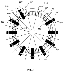
Figure 3 shows a diagrammatic view of a foundation of a wind power
installation according to a second embodiment.
Figure 1 shows a diagrammatic view of a foundation of a wind power
installation according to the invention. A lower pylon segment 100 is set in
place and then there is provided a reinforcement comprising steel rods or
bars and radial rods or bars 200. Then the foundation is filled with
concrete 300. The lower pylon segment 100 has holes (for example oval
holes) 110, through which radial bars of the reinforcement can be passed.
That can be effected to improve the statics of the foundation. Besides the
radial bars 200 there can also be peripherally extending bars or vertical
bars for the reinforcement. The lower pylon segment is preferably made
from steel and has an upper flange 120 and a lower flange 130, wherein
the upper flange projects out of the foundation and the lower flange 130 is
concreted in place.
Figure 2 shows a diagrammatic view of a holder according to a first
embodiment of the invention. The holder 400 has an upper bracket 410
and a lower foot 420 which are connected together. Preferably the upper
bracket 410 and the lower foot 420 are designed to be displaceable relative
to each other so that the length of the holder 400 is variable.
The upper bracket 410 has a first and a second end 411, 412,
wherein the first end 411 of the bracket 410 is adapted for fixing to for
example an upper flange 120 of the pylon segment 100. The lower foot
420 can be fixed to the second end 412 of the bracket 410. The flrst end

CA 02795286 2012-10-02
4
411 of the bracket 410 can be of an angled configuration and can have at
least one slot 430 so that the angled end 411 can be fixed to the flange
120 of the pylon segment 100 for example by means of screws and nuts.
The lower foot 420 has a first and second end 421, 422, wherein the first
end 421 of the foot 420 can be fixed to the second end 412 of the upper
bracket 410. In this case slots can be provided either at the first end 421
of the foot 420 or at the second end 412 of the bracket 410 so that the
bracket 410 and the foot 420 can be fixed together and the length of the
holder is variable. The second end 422 of the foot 420 is of angled
configuration and can optionally have an upwardly bent end. In this
arrangement the second end 422 of the lower foot 420 serves to receive
steel bars or radial bars of the reinforcement. In that respect in particular
an inner ring comprising at least one steel bar can be received around the
pylon segment. The radial bars of the reinforcement can be provided on or
at the inner ring. Those radial bars extend through the holes 110 in the
wall of the lower pylon segment 100. In that case the length of the holder
400 is preferably so adjusted that the radial bars are not in contact with the

wall of the lower pylon segment.
Figure 3 shows a diagrammatic view of a foundation of a wind power
installation according to a second embodiment. This Figure shows in
particular the lower pylon segment 100 with the holes 110. Radial bars
210 of the reinforcement are provided through the holes 110. Provided
around the pylon segment is at least one ring 220 comprising a steel bar.
That ring 220 can be provided beneath the plurality of radial bars 110. In
addition a plurality of holders 400 (for example holders according to the
first embodiment) is fixed with the first end on the pylon segment. The
second ends of the holders serve to receive the ring 220. Preferably the
length of the holders is so adjusted that the radial bars 210 on the ring 220
extend through the holes 110 without in that case touching the wall of the
pylon segment.
When the concrete is cast into the foundation the concrete can be
filled up until the reinforcement is covered. Therefore the lower foot of the
holder is also concreted in place. The upper brackets of the holder can

CA 02795286 2012-10-02
however be further used. For that purpose it is only necessary for the
lower foot to be removed (for example ground off). The upper brackets
can thus be re-used.
The above-described lower pylon segment is preferably a steel pylon
5 segment.

Representative Drawing
A single figure which represents the drawing illustrating the invention.
Administrative Status

For a clearer understanding of the status of the application/patent presented on this page, the site Disclaimer , as well as the definitions for Patent , Administrative Status , Maintenance Fee  and Payment History  should be consulted.

Administrative Status

Title Date
Forecasted Issue Date 2014-12-09
(86) PCT Filing Date 2011-04-21
(87) PCT Publication Date 2011-10-27
(85) National Entry 2012-10-02
Examination Requested 2012-10-02
(45) Issued 2014-12-09
Deemed Expired 2021-04-21

Abandonment History

There is no abandonment history.

Payment History

Fee Type Anniversary Year Due Date Amount Paid Paid Date
Request for Examination $800.00 2012-10-02
Application Fee $400.00 2012-10-02
Maintenance Fee - Application - New Act 2 2013-04-22 $100.00 2012-10-02
Registration of a document - section 124 $100.00 2013-04-16
Maintenance Fee - Application - New Act 3 2014-04-22 $100.00 2014-03-10
Final Fee $300.00 2014-09-17
Maintenance Fee - Patent - New Act 4 2015-04-21 $100.00 2015-04-08
Maintenance Fee - Patent - New Act 5 2016-04-21 $200.00 2016-04-07
Maintenance Fee - Patent - New Act 6 2017-04-21 $200.00 2017-04-10
Maintenance Fee - Patent - New Act 7 2018-04-23 $200.00 2018-04-11
Maintenance Fee - Patent - New Act 8 2019-04-23 $200.00 2019-04-11
Maintenance Fee - Patent - New Act 9 2020-04-21 $200.00 2020-04-06
Owners on Record

Note: Records showing the ownership history in alphabetical order.

Current Owners on Record
WOBBEN PROPERTIES GMBH
Past Owners on Record
None
Past Owners that do not appear in the "Owners on Record" listing will appear in other documentation within the application.
Documents

To view selected files, please enter reCAPTCHA code :


To view images, click a link in the Document Description column. To download the documents, select one or more checkboxes in the first column and then click the "Download Selected in PDF format (Zip Archive)" or the "Download Selected as Single PDF" button.

List of published and non-published patent-specific documents on the CPD .

If you have any difficulty accessing content, you can call the Client Service Centre at 1-866-997-1936 or send them an e-mail at CIPO Client Service Centre.


Document
Description 
Date
(yyyy-mm-dd) 
Number of pages   Size of Image (KB) 
Abstract 2012-10-02 1 17
Claims 2012-10-02 2 50
Drawings 2012-10-02 3 64
Description 2012-10-02 5 193
Representative Drawing 2012-11-28 1 11
Cover Page 2012-11-30 2 48
Abstract 2014-04-07 1 17
Claims 2014-04-07 2 52
Description 2014-04-07 5 190
Cover Page 2014-11-20 2 50
PCT 2012-10-02 8 338
Assignment 2012-10-02 3 118
Correspondence 2014-09-17 2 57
Assignment 2013-04-16 27 859
Prosecution-Amendment 2013-10-11 2 50
Prosecution-Amendment 2014-04-07 8 233