Note: Descriptions are shown in the official language in which they were submitted.
CA 02795427 2012-10-03
1
DESCRIPTION
Title of Invention: PLANETARY GEAR SYSTEM
Technical Field
[0001] The present invention relates to a planetary gear system mainly used in
a power
transmission mechanism of an aircraft, and particularly to a lubricating
structure of such
a planetary gear system.
Background Art
[0002] In recent years, one of the key issues in the aircraft industry is to
improve the
fuel efficiency of aircrafts from the viewpoint of reduction of aircraft
operation costs as
well as environmental conservation. Accordingly, reduction in power loss of
planetary
gear systems for use in aircraft engines is also required.
[0003] Conventionally, such a planetary gear system includes a mechanism for
supplying lubricating oil to the gears for the purpose of lubricating and
cooling down the
gears. Here, agitation resistance of the lubricating oil that is supplied
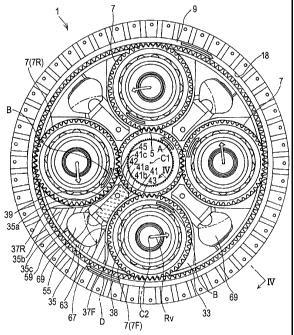
around the gears
is one of the main causes of power loss in the planetary gear system. One of
the
techniques proposed for reducing such agitation resistance of lubricating oil
is, for
example, as follows: lubricating oil that has been supplied to a mesh position
between a
sun gear and a planet gear is discharged axially by utilizing rotation of the
planet gear
which is a double helical gear, and a baffle (a barrier) is provided between
adjacent
planet gears, so that generation of a swirl flow due to interference of flows
of lubricating
oil that are generated around the adjacent planet gears is suppressed (see
Patent
Literature 1, for example).
Citation List
=
CA 02795427 2014-05-07
2
Patent Literature
[0004] PTL 1: Japanese National Phase PCT Laid-Open Publication No. 9-507284
Summary of Invention
Technical Problem
[0005] However, in relation to the above structure, there is a conceivable
problem as
described below. In the above structure, the lubricating oil which is a fluid
is discharged from
the axially central portion of the double helical gear in both outward
directions. Here, no
locally vacuum portion occurs in the fluid. Considering such continuity of the
fluid, it is
presumed that efficient discharging of the lubricating oil is difficult.
Moreover, since a baffle
is disposed near the outer periphery of a planet gear, the lubricating oil
that exits the mesh
position flows out while being adhered to the outer periphery of the planet
gear. As a result,
the agitation resistance of the lubricating oil increases.
[0006] Furthermore, it is difficult to reduce power loss sufficiently unless
not only
lubricating oil around the central sun gear and planet gears but also
lubricating oil around
other rotating components, such as an outer peripheral ring gear and bearings
provided in the
planetary gear system, are smoothly discharged.
[0007] An object of the present invention is to provide a planetary gear
system with reduced
power loss, by reducing lubricating oil agitation resistance through efficient
discharging of
lubricating oil supplied to main rotating components of the planetary gear
system.
CA 02795427 2014-05-07
3
Solution to Problem
[0008] Certain exemplary embodiments can provide a planetary gear system
comprising: a
sun gear having external teeth; a plurality of planet gears having external
teeth, each planet
gear meshing with the sun gear; a ring gear having internal teeth, the ring
gear meshing with
the planet gears; and a baffle unit disposed between the planet gears which
are adjacent to
each other, the baffle unit having side faces positioned near outer
peripheries of the respective
planet gears, wherein the baffle unit has: oil supply holes which are formed
in a tip portion
facing an outer periphery of the sun gear and which jet out lubricating oil to
mesh positions
between the sun gear and the planet gears; a collection opening which is
formed in at least one
of the side faces and through which the lubricating oil that has been jetted
out is collected into
the baffle unit; and a collection chamber which is formed inside of the baffle
unit and
provisionally stores the lubricating oil that is collected through the
collection opening.
[0009] According to this structure, the baffle unit is provided between the
planet gears
which are adjacent to each other, and the baffle unit collects the lubricating
oil therein while
preventing flows of the lubricating oil around the respective adjacent planet
gears from
interfering with each other. This makes it possible to prevent a large amount
of lubricating oil
from being adhered to the outer periphery of the planet gears over a long
circumferential
distance. Accordingly, the agitation resistance of the lubricating oil is
reduced. As a result,
power loss of the planetary gear system is reduced.
CA 02795427 2014-05-07
_
3a
[0010] In the planetary gear system according to the present invention, each
planet gear is
preferably a double helical gear having an annular groove formed at an outer
circumferential
face of an axially central portion of the double helical gear. According to
this structure, the
lubricating oil can be collected into the annular groove of the axially
central portion of each
planet gear by utilizing rotation of the planet gear. This makes it possible
to efficiently
discharge the lubricating oil.
[0011] In the planetary gear system according to the present invention, it is
preferred that
a guide piece which guides the lubricating oil to the collection opening is
formed at
CA 02795427 2012-10-03
4
the at least one of the side faces of the baffle unit. According to this
structure, the
amount of lubricating oil that flows outward in the planetary gear system
beyond the
collection opening can be reduced. Therefore, the lubricating oil can be very
efficiently
collected into the baffle unit through the collection opening.
[0012] In the planetary gear system according to the present invention, it is
preferred
that the baffle unit has a ring gear oil supply hole formed therein, through
which the
collected lubricating oil is supplied to the ring gear. According to this
structure, the
lubricating oil that has been collected into the baffle unit can be discharged
to the radially
outer side of the planetary gear system, and also, the lubricating oil can be
used to
lubricate the ring gear. This makes it possible to effectively reduce power
loss of the
planetary gear system.
[0013] In the planetary gear system according to the present invention, it is
preferred
that the baffle unit has an outlet formed therein, through which the collected
lubricating
oil is discharged in an axial direction. According to this structure, the
collected
lubricating oil is discharged in the axial direction, and thereby the
collection of the
lubricating oil can be facilitated. Therefore, the agitation resistance can be
reduced
more effectively.
[0014] In the planetary gear system according to the present invention, the
baffle unit
may include a weir, which blocks the outlet at a radially outer side of the
planet gears and
at a backward side with respect to a revolution direction of the planet gears.
Since the
weir is provided at the outlet as described above, a sufficient amount of
lubricating oil to
be supplied to the ring gear through the ring gear oil supply hole can be kept
within the
baffle unit. In particular, Centrifugal force and Coriolis force generated by
revolution
of the planet gears are both exerted on the lubricating oil that has been
collected into the
baffle unit. Accordingly, the lubricating oil can be effectively kept by
blocking, with
CA 02795427 2012-10-03
,
the weir, the outlet at the radially outer side of the planet gears and at the
backward side
with respect to the revolution direction of the planet gears, that is, by
blocking, with the
weir, a portion positioned in the direction of resultant force of the
centrifugal force and
the Coriolis force.
[0015] In the planetary gear system according to the present invention, it is
preferred
that a collection guide groove which guides the lubricating oil to the
collection opening
is formed so as to extend from an inner end of the at least one of the side
faces of the
baffle unit to the collection opening. According to this structure, the
lubricating oil can
be collected more effectively.
Advantageous Effects of Invention
[0016] According to the planetary gear system of the present invention,
lubricating oil
supplied to main rotating components of the planetary gear system can be
efficiently
discharged. As a result, the agitation resistance of the lubricating oil is
reduced, and
thereby power loss of the planetary gear system is reduced greatly.
Brief Description of Drawings
[0017] [Fig. 1] Fig. 1 is a partially cutaway perspective view showing a
planetary gear
system according to one embodiment of the present invention.
[Fig. 2] Fig. 2 is a longitudinal sectional view of the planetary gear system
shown in Fig. 1.
[Fig. 3] Fig. 3 is a transverse sectional view of the planetary gear system
shown
in Fig. 1.
[Fig. 4] Fig. 4 is a cross-sectional view along line IV-IV indicated in Fig.
3.
[Fig. 5] Fig. 5 is a perspective view of baffle units shown in Fig. 3.
CA 02795427 2012-10-03
6
[Fig. 6] Fig. 6 is a cross-sectional view of a variation of the planetary gear
system shown in Fig. 3.
[Fig. 7] Fig. 7 is a cross-sectional view showing a main part of Fig. 3 in an
enlarged manner.
[Fig. 8] Fig. 8 is a front view of a planet gear for use in the planetary gear
system shown in Fig. 1.
[Fig. 9] Fig. 9 is a transverse sectional view of a ring gear for use in the
planetary gear system shown in Fig. 1.
Description of Embodiments
[0018] Hereinafter, a preferred embodiment of the present invention is
described with
reference to the accompanying drawings. Fig. 1 is a perspective view showing a
planetary gear system 1 according to one embodiment of the present invention.
The
planetary gear system 1 is installed in an aircraft engine, and transmits
power of an input
shaft 3 as two outputs. It should be noted that in the description below,
along the axial
direction of the planetary gear system 1, one side of the planetary gear
system 1, at which
side the engine is disposed (i.e., the lower left side in Fig. 1), is referred
to as a front side,
and the opposite side is referred to as a rear side.
[0019] The planetary gear system 1 is configured as a double-row gear
mechanism,
which includes: a central sun gear 5; planet gears 7; and an outer ring gear
9. The sun
gear 5 is a double helical gear including a pair of helical gears and having
sets of external
teeth, the sets of external teeth being inclined in respective directions that
are opposite to
each other. The sun gear 5 is fitted to the outer periphery of the input shaft
3 which acts
as the rotational axis. Each planet gear 7 is a double helical gear having a
pair of sets of
external teeth, and includes helical gears corresponding to the helical gears
of the sun
CA 02795427 2012-10-03
7
gear 5. Each planet gear 7 meshes with the sun gear 5. As described in detail
below in
this embodiment, four planet gears 7 are arranged in the circumferential
direction of the
sun gear 5 at equal intervals. The ring gear 9 is a double helical gear
including a pair of
helical gears with internal teeth. The ring gear 9 meshes with the four planet
gears 7.
The sun gear 5 has an annular groove 16 formed at its axially central portion,
that is, at
its outer circumferential face between the pair of sets of teeth. Also, each
planet gear 7
has an annular groove 17 formed at its axially central portion, that is, at
its outer
circumferential face between the pair of sets of teeth. Further, the ring gear
9 has an
annular groove 18 formed at its axially central portion, that is, at its inner
circumferential
face between the pair of sets of teeth. Fig. 2 is a longitudinal sectional
view showing a
main part of the planetary gear system 1 in Fig. 1. In Fig. 2, the front side
is on the left,
and the rear side is on the right. As shown in Fig. 2, each planet gear 7 is
rotatably
supported, via a respective double row bearing 15, at the outer periphery of a
corresponding planet shaft 13 which has a hollow center. Both front and rear
ends of
the planet shaft 13 are attached to a planet carrier 11.
[0020] The front end of the planet shaft 13 is supported by an annular front
plate 19
which shares the same central axis Cl with the input shaft 3. On the other
hand, the
rear end of the planet shaft 13 is supported by an annular back plate 21 which
is disposed
concentrically to the front plate 19. As described in detail below, the back
plate 21 is
connected and fixed to the front plate 19 via fixed support shafts 23. The
front plate 19
and the back plate 21, which are connected to each other by bolts via the
fixed support
shafts 23, form the planet carrier 11 which supports the planet shafts 13 and
the planet
gears 7. The planet carrier 11 determines the relative positions of the planet
shafts 13
relative to one another, that is, determines the relative positions of the
planet gears 7
relative to one another.
CA 02795427 2012-10-03
8
[0021] The front end of each planet shaft 13 in the axial direction penetrates
through the
front plate 19, and the rear end of each planet shaft 13 in the axial
direction penetrates
through the back plate 21. The front plate 19 is fixed to the front end of
each planet
shaft 13 in the axial direction by means of the respective fixed support shaft
23, which is
a headed shaft having a hollow center and which is inserted in the hollow
center of the
corresponding planet shaft 13 through the front end of the planet shaft 13.
The back
plate 21 is fixed to the rear end of each planet shaft 13 in the axial
direction by means of
a respective headed nut threadably mounted to a female screw provided at the
rear end of
the corresponding planet shaft 13. In this manner, the front plate 19, the
planet shafts
13, and the back plate 21 are fastened in the axial direction and thereby
fixed. For each
planet shaft 13, cushioning 28 and a spacer 29 are interposed between the
outer periphery
of the planet shaft 13 and the front plate 19, as well as between the outer
periphery of the
planet shaft 13 and the back plate 21.
[0022] A front output shaft OF, which is concentric to the input shaft 3, is
connected to
the outer circumferential face of the front plate 19. Power derived from
revolution of
the four planet gears 7 around the system's central axis Cl is outputted
frontward via the
front output shaft OF. A rear output shaft OR, which is concentric to the
input shaft 3,
is connected to the rear side of the outer periphery of the ring gear 9. Power
derived
from rotation of each planet gear 7 around its rotational central axis C2 is
outputted
rearward via the ring gear 9 and the rear output shaft OR. It should be noted
that, as an
alternative, the ring gear 9 may be set to be not rotatable or the planet
carrier 11 may be
set to be not rotatable, such that the power is outputted either frontward
only or rearward
only.
[0023] Fig. 3 shows a transverse sectional view of the planetary gear system 1
along
line indicated in Fig. 2. The four planet gears 7 are arranged in the
CA 02795427 2012-10-03
9
circumferential direction at equal intervals between the sun gear 5 and the
ring gear 9.
There are multiple intergear spaces 33 (in this embodiment, four intergear
spaces 33 in
total), each of which is surrounded by the sun gear 5, two planet gears 7 that
are adjacent
to each other in the circumferential direction, and the ring gear 9. A baffle
unit 35 is
provided in each intergear space 33. Hereinafter, the structure of the baffle
unit 35 is
described in detail. It should be noted that, when one among the baffle units
35 is
referred to in the description below, the planet gear 7 that is positioned
forward from the
one baffle unit 35 with respect to the counterclockwise revolution direction
Rv of the
planet gears 7 may be called a "forward planet gear 7F", and the planet gear 7
that is
positioned backward from the one baffle unit 35 with respect to the revolution
direction
Rv may be called a "backward planet gear 7R".
[0024] Each baffle unit 35 includes an inner portion 35a and an outer portion
35b. The
inner portion 35a is positioned at the radially inner part of the intergear
space 33, which
is a part close to the system's central axis Cl. The outer portion 35b is
positioned at the
radially outer part of the intergear space 33, which is a part close to the
ring gear 9. In
the diagram, the inner portion 35a is indicated by dashed-line hatching, and
the outer
portion 35b is indicated by solid-line hatching.
[0025] As shown in Fig. 3, the baffle unit 35 has a forward side face 37F
which is
formed in a recessed curved shape. The forward side face 37F has a part that
extends
substantially along the outer circumferential shape of the forward planet gear
7F, the part
extending from the inner portion 35a to the inner part of the outer portion
35b. The
forward side face 37F of the baffle unit 35 is positioned near the forward
planet gear 7F.
A forward gap 38 having a curved transverse sectional shape is formed between
the
forward side face 37F of the baffle unit 35 and the forward planet gear 7F.
Similarly,
the inner portion 35a of the baffle unit 35 has a backward side face 37R which
is formed
CA 02795427 2012-10-03
in a recessed curved shape and which extends substantially along the outer
circumferential shape of the backward planet gear 7R. The backward side face
37R of
the baffle unit 35 is positioned near the backward planet gear 7R. A backward
gap 39
having a curved transverse sectional shape is formed between the backward side
face
37R of the baffle unit 35 and the backward planet gear 7R.
[0026] The baffle unit 35 has a tip portion 41 which faces the outer periphery
of the sun
gear 5. The tip portion 41 has a tip face 41a which is positioned near the sun
gear 5 and
which has a curved shape substantially extending along the outer periphery of
the sun
gear 5. The tip face 4Ia of the baffle unit 35 is positioned near the sun gear
5. An
inner gap 42 having a curved transverse sectional shape is formed between the
tip face
41a of the baffle unit 35 and the sun gear 5. A forward inclined face 41b is
formed at
one end of the tip face 41a of the baffle unit 35 and a backward inclined face
41c is
formed at the other end of the tip face 41a of the baffle unit 35. The forward
inclined
face 41b faces a mesh position 43 between the sun gear 5 and the forward
planet gear 7F
(forward mesh position). The backward inclined face 41c faces a mesh position
45
between the sun gear 5 and the backward planet gear 7R (backward mesh
position).
[0027] Preferably, the size of each of the forward gap 38, the backward gap
39, and the
inner gap 42 is in the range of 3 to 7 mm. More preferably, the size of each
gap is in the
range of 4 to 6 mm. Setting the size of each gap within this range makes it
possible to
suppress an increase in the overall size of the planetary gear system 1 and to
sufficiently
obtain a path for lubricating oil OL that has not flowed into any of the
annular grooves 16,
17, and 18 of the sun gear 5, the planet gears 7, and the ring gear 9 (see
Fig. 1) and that
remains on the tooth surface of these gears. This contributes to reducing the
agitation
resistance of the lubricating oil OL.
[0028] Fig. 4 is a cross-sectional view along line IV-IV indicated in Fig. 3.
In Fig. 4,
CA 02795427 2012-10-03
11
the front side is on the left, and the rear side is on the right. As shown in
Fig. 4, the
inner portion 35a of the baffle unit 35 is formed as a solid portion, and is
fixed to the
back plate 21 by bolts 49. The front plate 19 and the back plate 21 are
connected to
each other by a bolt 51. A gear lubricating oil guide path 53A is formed at
the inner
portion 35a of the baffle unit 35. A gear lubricating oil guide path 53B is
formed at the
front plate 19. These gear lubricating oil guide paths 53A and 53B communicate
with
oil supply holes 47 which will be described below. At the inner
circumferential portion
of the front plate 19, a cylindrical portion 19a is formed to protrude
frontward in the
axial direction. The gear lubricating oil guide path 53B communicates with the
outside
via the outer circumferential face of the cylindrical portion 19a.
[0029] As shown in Fig. 5, the forward inclined face 41b and the backward
inclined
face 41c of the baffle unit 35 are each provided with multiple oil supply
holes 47 (in this
embodiment, six oil supply holes 47) which are arranged in the axial
direction. The oil
supply holes 47 are provided for jetting out the lubricating oil OL which is
supplied from
the outside.
[0030] A backward collection opening 55 is formed in the backward side face
37R of
the baffle unit 35, such that the backward collection opening 55 is located at
a position
near the boundary between the inner portion 35a and the outer portion 35b,
which
position is substantially the central position of the backward side face 37R
in the axial
direction. The backward collection opening 55 is provided for collecting the
jetted
lubricating oil OL into the baffle unit 35. The backward collection opening 55
is open
in the inner radial direction of the planetary gear system I. A collection
guide groove
57 for guiding the lubricating oil OL to the backward collection opening 55 is
formed so
as to extend from the inner end of the backward side face 37R to the backward
collection
opening 55. The collection guide groove 57 has an axial direction width W,
which is
CA 02795427 2012-10-03
12
greatest at the inner end of the backward side face 37R. The shorter the
distance to the
backward collection opening 55, which is located outer than the inner end of
the
backward side face 37R, the smaller is the axial direction width W.
[0031] The collection guide groove 57 has a central portion 57a which is
formed as a
deeper groove than its adjacent portions. The central portion 57a is the
central portion
of the collection guide groove 57 in the axial direction, and its position in
the axial
direction corresponds to that of the annular groove 17 (Fig. 2) of the planet
gear 7. It
should be noted that the multiple oil supply holes 47 are not formed at axial
directional
positions that correspond to the position, in the axial direction, of the
central portion 57a
of the collection guide groove 57, but are formed at equal intervals at more
frontward
and rearward positions in the axial direction. That is, the multiple oil
supply holes 47
are formed such that their positions in the axial direction correspond to the
positions of
the teeth of the planet gear 7 and the teeth of the sun gear 5 in the axial
direction (Fig. 2).
[0032] Further, as shown in Fig. 5, ring gear oil supply holes 59, which are
through-holes extending in the radial direction, are formed in a wall 35c of
the baffle unit
35. The wall 35c is the outermost portion of the baffle unit 35. The ring
gear oil
supply holes 59 (in this embodiment, two ring gear oil supply holes 59) in the
wall 35c
are arranged in the axial direction with a predetermined interval
therebetween. The ring
gear oil supply holes 59 are arranged at positions that are located backward
from the
center of the wall 35c with respect to the revolution direction Rv of the
planet gear 7. It
should be noted that the number and the positions of the oil supply holes 47
and the ring
gear oil supply holes 59 may be set to any number and positions as
appropriately.
[0033] A forward collection opening 63 is formed in the forward side face 37F
of the
baffle unit 35, such that the forward collection opening 63 is located at the
substantially
central position in the axial direction at the outer end of the forward side
face 37F, that is,
CA 02795427 2012-10-03
13
near the boundary between the inner portion 35a and the outer portion 35b. The
forward collection opening 63 is provided for collecting the jetted
lubricating oil OL into
the baffle unit 35. The forward collection opening 63 is open inward in a
direction
diagonal to the radial direction of the planetary gear system 1.
[0034] It should be noted that, as in a variation shown in Fig. 6, a guide
piece 61 may
be provided at the outer side of the backward collection opening 55. The guide
piece 61
provided at the outer side of the backward collection opening 55 is a claw-
like member
which protrudes inward. The tip of the guide piece 61 is positioned within the
annular
groove 17 which is formed at the center of the planet gear 7. The guide piece
61 blocks
the lubricating oil OL from flowing outward beyond the backward collection
opening 55,
and guides the lubricating oil OL into the backward collection opening 55. The
guide
piece 61 may be formed to be integrated with the baffle unit 35.
Alternatively, the
guide piece 61 may be formed as a separate component from the baffle unit 35,
and then
joined to the baffle unit 35 by welding or the like.
[0035] As shown in Fig. 4, the outer portion 35b of the baffle unit 35 is
formed to have
a hollow center. The inner space of the baffle unit 35 communicates with the
backward
collection opening 55 and the forward collection opening 63, and acts as a
collection
chamber 65 which provisionally stores the lubricating oil OL that is collected
through
these collection openings 55 and 63. An opening of the collection chamber 65
at the
rear end in the axial direction is fully sealed by the back plate 21.
Meanwhile, an
opening of the collection chamber 65 at the front end in the axial direction
acts an axial
directional outlet 67 for discharging the lubricating oil OL from the
collection chamber
65 to the outside of the baffle unit 35 in the axial direction. The axial
directional outlet
67 is partially blocked by a weir 69.
[0036] As shown in Fig. 7 which is an enlarged view of a main part of Fig. 3,
the weir
CA 02795427 2012-10-03
14
69 blocks the radially outer side of the axial directional outlet 67 and the
backward side
of the axial directional outlet 67 with respect to the revolution direction
Rv. Centrifugal
force Cf and Coriolis force Co generated by the revolution of the planet gear
7 are both
exerted on the lubricating oil OL that is collected within the collection
chamber 65 of the
baffle unit 35. Accordingly, the lubricating oil OL can be effectively caught
into the
collection chamber 65 by blocking, with the weir 69, the radially outer side
of the axial
directional outlet 67 and the backward side of the axial directional outlet 67
with respect
to the revolution direction Rv, that is, by blocking, with the weir 69, a
portion positioned
in the direction of resultant force Re of the centrifugal force Cf and the
Coriolis force Co.
Moreover, since the ring gear oil supply holes 59 in the wall 35c are arranged
at positions
that are located backward from the center of the wall 35c with respect to the
revolution
direction Rv of the planet gear 7, the lubricating oil OL is assuredly
supplied to the ring
gear 9 through the ring gear oil supply holes 59.
[0037] Next, a lubricating structure of the bearing 15 and a lubricating oil
drainage
structure are described with reference to Fig. 2. The bearing 15, which is
disposed
between the planet gear 7 and the planet shaft 13, is formed as a double-row
roller
bearing which includes two rolling element rows 72. Each rolling element row
72
includes: multiple rolling elements 73 which are cylindrical rollers; and an
annular
retainer 75 holding the rolling element row 72. The planet shaft 13 acts as an
inner ring
for the bearing 15. For each rolling element row 72, a rolling surface 77 for
the rolling
elements 73 is formed on the outer circumferential face of the planet shaft
13. Further,
annular flanges 79 for restricting the position of the rolling elements 73 in
the axial
direction are provided at both ends of each rolling surface 77 in the axial
direction.
[0038] In the peripheral wall of the planet shaft 13 having a hollow center, a
pair of
bearing oil supply holes 81A and 81B are formed at both ends, in the axial
direction, of
=
CA 02795427 2012-10-03
each rolling surface 77. Specifically, the pair of bearing oil supply holes
81A and 81B
extend in the radial direction through the vicinity of the base portions of
the respective
flanges 79. A recess 23a, which communicates with the bearing oil supply holes
81A
and 81B, is formed at the outer circumferential face of the fixed support
shaft 23.
Space formed by the recess 23a and the inner circumferential face 13a of the
planet shaft
13 acts as oil reservoir space 83 for storing the lubricating oil OL. The
planet shaft 13
is provided with a through-hole 85, which extends in the radial direction and
of which
the position in the axial direction corresponds to that of the front end of
the recess 23a.
Further, a bearing lubricating oil guide path 87, which communicates with the
through-hole 85, is formed within the radially inner portion of the front
plate 19. The
bearing lubricating oil guide path 87 of the front plate 19 communicates with
an external
lubricating oil source (not shown) through the outer circumferential face of
the
cylindrical portion 19a, which is formed at the inner circumferential portion
of the front
plate 19 and which protrudes frontward in the axial direction.
[0039] The bearing lubricating oil guide path 87 of the front plate 19 (planet
carrier 11),
the through-hole 85 of the planet shaft 13, the oil reservoir space 83, and
the bearing oil
supply holes 81A and 81B of the planet shaft (inner ring) 13, which are formed
as
described above, collectively serve as a bearing oil supply path LP through
which the
lubricating oil OL is supplied to the rolling elements 73 of the bearing 15.
Through the
bearing oil supply path LP, the lubricating oil OL that is sent from the
radially inner side
of the planet gear 7 is supplied to both ends of each rolling element 73 which
is a
cylindrical roller.
[0040] As described above, the planet gear 7 is formed as a double helical
gear, which
includes a pair of helical gears aligned in the axial direction, and the
annular groove 17 is
formed between the pair of helical gears. As shown in Fig. 8, multiple oil
outlets 91 are
CA 02795427 2012-10-03
,
16
formed at the annular groove 17 of the planet gear 7 as through-holes
extending in the
radial direction. These oil outlets 91 are arranged at equal intervals in the
circumferential direction. The planet gear 7 rotates in a direction indicated
by arrow B,
which is opposite to a direction in which one set of helical teeth and the
other set of
helical teeth of the double helical gear are inclined toward each other.
Therefore, when
the lubricating oil OL is supplied to the gear tooth surfaces, the lubricating
oil OL flows
into the annular groove 17 positioned at the center of the planet gear 7.
[0041] Further, as shown in Fig. 9, the ring gear 9 is formed as a double
helical gear,
which includes a pair of helical gears aligned in the axial direction, and the
annular
groove 18 is formed between the pair of helical gears. The ring gear 9 is
divided in the
axial direction into two portions that are a gear half body 9a and a gear half
body 9b.
Teeth formed on one of the gear half bodies are inclined in a direction that
is opposite to
the inclination direction of teeth formed on the other one of the gear half
bodies.
Multiple outlets 93 are formed at the annular groove 18 of the ring gear 9 as
through-holes extending in the radial direction. The outlets 93 are arranged
at equal
intervals in the circumferential direction.
[0042] Next, the operation of the planetary gear system 1 according to the
above
embodiment will be described.
[0043] The sun gear 5 of the planetary gear system 1 shown in Fig. 3 rotates
in a
direction indicated by arrow A. The driving force of the rotation causes the
planet gears
7 to rotate in a direction indicated by arrow B, and also causes the planet
gears 7 to
revolve in a direction indicated by arrow Rv together with the planet carrier
11. The
ring gear 9 rotates in a direction indicated by arrow D.
[0044] The lubricating oil OL that is supplied from the outside and that is
guided into
the baffle unit 35 through the gear lubricating oil guide paths 53 (see Fig.
2) is jetted
CA 02795427 2012-10-03
17
toward the forward mesh position 43 through the oil supply holes 47 of the
forward
inclined face 41b of the baffle unit 35 and toward the backward mesh position
45 through
the oil supply holes 47 of the backward inclined face 41c of the baffle unit
35. The
temperature at a position where the teeth of gears come out of mesh becomes
higher than
the temperature at a position where the teeth of gears come into mesh.
Therefore, for
the purpose of cooling down such a temperature-increased position, the amount
of
lubricating oil OL supplied to the backward mesh position 45 where the teeth
of the gears
come out of mesh is greater than the amount of lubricating oil OL supplied to
the forward
mesh position 43. A part of the lubricating oil OL jetted toward the backward
mesh
position 45 flows outward through the backward gap 39 between the backward
side face
37R of the baffle unit 35 and the backward planet gear 7R. Most of the
lubricating oil
OL flowing through the backward gap 39 is collected into the baffle unit 35
through the
backward collection opening 55. In particular, the lubricating oil OL that has
been used
for lubricating the backward planet gear 7R and the sun gear 5 flows into the
annular
groove 17 shown in Fig. 8, owing to the rotation of the planet gear 7 which is
a double
helical gear. Then, the lubricating oil OL passes through the backward mesh
position
45 shown in Fig. 3 and flows into the collection guide groove 57 of the baffle
unit 35
(specifically, the central portion 57a shown in Fig. 5). Thereafter, the
lubricating oil OL
is collected into the baffle unit 35 through the backward collection opening
55. On the
other hand, a part of the lubricating oil OL that is jetted through the oil
supply holes 47
toward the forward mesh position 43 shown in Fig. 3 is collected into the
baffle unit 35
through the forward collection opening 63.
[0045] The lubricating oil OL collected into the baffle unit 35 flows into the
collection
chamber 65. Thereafter, a part of the lubricating oil OL is held back by the
weir 69 and
then supplied to the ring gear 9 through the ring gear oil supply holes 59. In
this
CA 02795427 2012-10-03
18
manner, the ring gear 9 is effectively lubricated. The lubricating oil OL that
overflows
the weir 69 of the collection chamber 65 is discharged through the axial
directional outlet
67 to the outside of the planetary gear system 1 in the frontward axial
direction.
[0046] As described above, the baffle unit 35 is provided between the adjacent
planet
gears 7. The baffle unit 35 collects the lubricating oil OL therein while
preventing
flows of the lubricating oil around the respective adjacent planet gears 7
from interfering
with each other. This makes it possible to prevent a large amount of
lubricating oil OL
from being adhered to the outer periphery of the planet gears 7 over a long
circumferential distance. Accordingly, the agitation resistance of the
lubricating oil OL
is reduced. As a result, power loss of the planetary gear system 1 is reduced.
It was
confirmed through an experiment that power loss was reduced by 34 percent as
compared
to conventional art that does not include components corresponding to the
collection
openings 55 and 63 of the baffle unit 35 and the oil outlets 91 of the planet
gear 7.
[0047] The lubricating oil OL that is supplied from the outside to the rolling
elements
73 of the bearing 15 through the bearing oil supply path LP shown in Fig. 2
is, after
lubricating the rolling elements 73, discharged to the outside of the planet
gear 7. Here,
the lubricating oil OL that is supplied to the rolling elements 73 through the
bearing oil
supple hole 81A which is disposed at an outer position in the axial direction
is, after
lubricating the rolling elements 73, discharged outward in the axial
direction. On the
other hand, the lubricating oil OL that passes through the bearing oil supply
hole 81B
which is disposed at an inner position in the axial direction enters space 96
between the
two rolling element rows after lubricating the rolling elements 73. Then, at
each rolling
element row, as indicated by arrows G, a part of the lubricating oil OL passes
between
rolling elements 73 that are adjacent to each other in the circumferential
direction, and is
discharged outward in the axial direction. Another part of the lubricating oil
OL is
CA 02795427 2012-10-03
19
discharged to the radially outer side through the oil outlets 91. The
lubricating oil OL
that passes between rolling elements 73 as indicated by arrows G increases the
agitation
resistance for the rolling elements 73. However, by forming the oil outlets
91, the
amount of lubricating oil OL passing between the rolling elements 73 is
reduced.
Accordingly, the agitation resistance is reduced.
[0048] The lubricating oil OL that is supplied to the ring gear 9 through the
ring gear oil
supply holes 59 of the baffle unit 35 and the oil outlets 91 of the planet
gear 7 flows into
the annular groove 18 after lubricating the gear tooth surfaces of the ring
gear 9, and is
then discharged in the radial direction to the outside of the planetary gear
system 1 from
the outlets 93.
[0049] As described above, the oil outlets 91 are formed in the planet gear 7
located at a
radially outer position than the rolling elements 73 which are supplied with
the
lubricating oil OL. This makes it possible to efficiently discharge, to the
outside of the
planet gear 7, the lubricating oil OL that is supplied to the rolling elements
73 from the
radially inner side. Accordingly, the agitation resistance of the lubricating
oil OL
around the rolling elements 73 is reduced. As a result, power loss of the
planetary gear
system is reduced significantly. In addition, the lubricating oil OL that is
discharged
from the planet gear 7 can be used for lubricating the ring gear 9 which is
disposed at a
radially outer position than the planet gear 7.
[0050] It should be noted that the structure of the planet gear 7, in which
the lubricating
oil OL that has been supplied to the bearing 15 is discharged to the radially
outer side
through the oil outlets 91 which communicate with the space between the two
rolling
element rows which are aligned in the axial direction, is applicable not only
to the
above-described planetary gear system 1 but to any gear system, so long as the
gear
system includes a gear that is rotatably supported by a fixed support shaft
via a pair of
CA 02795427 2012-10-03
rolling element rows that are aligned in the axial direction.
[0051] Although a preferred embodiment of the present invention is as
described above
with reference to the drawings, various additions, modifications, and
deletions may be
made to the above embodiment without departing from the spirit of the present
invention.
Therefore, such additions, modifications, and deletions also fall within the
scope of the
present invention.
Industrial Applicability
[0052] According to the present invention, the lubricating oil that is
supplied to main
rotating components of the planetary gear system is efficiently discharged,
and thereby
power loss is reduced. Thus, the present invention is useful to reduce power
loss in a
planetary gear system.
Reference Signs List
[0053] 1 planetary gear system
5 sun gear
7 planet gear
9 ring gear
11 planet carrier
13 planet shaft
17 annular groove of planet gear
35 baffle unit
37F, 37R side face of baffle unit
41 tip portion of baffle unit
43, 45 mesh position
CA 02795427 2012-10-03
21
47 oil supply hole
55 collection opening
OL lubricating oil