Note: Descriptions are shown in the official language in which they were submitted.
CA 02795752 2012-11-15
1
Proximity warning system for helicopters
Technical Field
The present invention relates to a proximity warning system
for helicopters with the features of the preamble of claiml.
Background of the Invention
There is a need for a helicopter obstacle detection and rotor
strike warning system.
The document DE4328573 Al discloses an all-weather sight
system which combines information from a radar sensor based on
ROSAR with navigation and flight control information to produce a
synthetic sight for the pilot. In this case, the radar uses the rotary
movements of rotating arms - in this case in the form of a capstan
(spider) mounted above the rotor axis - which is protected against
aerodynamic forces by an aerodynamically formed body (radome).
The radar transmitter as well as the radar receiver are positioned
on the rotor head.
The document W02011136707 Al discloses a helicopter
obstacle detection and information system arranged to transmit
laser light and receive reflected laser light from obstacles for
detecting and informing the pilot of a helicopter of obstacles in
proximity of the helicopter. The system comprises an obstacle
detection sensor unit, being arranged to be mounted on a rotor
head of a helicopter such that said obstacle detection sensor unit
is arranged to rotate with said rotor head. The system further
comprises an information unit. The transmitted laser light is
arranged to cover a sector volume around a rotor head axis,
having a coverage defined as a radial extension (R1, R2) in a
sector plane around said rotor head axis and an angular extension
CA 02795752 2012-11-15
2
perpendicular to said sector plane. Communication means are
arranged for communication between said sensor unit and said
information unit.
The document DE102006053354 Al discloses a system with
radar sensors (RSO, RSm, RS (m+1), RSn) transmitting signals to
a detection and evaluation unit, where the signals represent
distance information. The unit displays the signals on a cockpit-
display after processing and comparing the information with a
preset warning threshold value. The sensors operate with short-
range and long-range wavelengths for scanning a sphere within,
rear and lateral of the helicopter and a sphere in front of a
helicopter, respectively. The information regarding obstacles
displayed on the cockpit display is restricted to distances in a
number of sectors. A footprint is received by the signals for
identification and differentiation between aircrafts.
The document DE 10 015 164 Al discloses a method of
operating a heliradar with a laser radar in a helicopter, using a
sensor. The sensor data is merged with a data registered in an on-
board-intrinsic database and accordingly the flight path and the
landing location are displayed in a virtual cockpit display. The
method involves the operation of a heliradar with a laser radar in a
helicopter, using a sensor. The sensor data is merged with a data
registered in an on-board-intrinsic database and accordingly the
flight path and the landing location are displayed in a virtual
cockpit display
The document W02007/024635 A2 discloses an obstacle
avoidance system including an input control device, a sensor suite,
and a communication feedback loop. The input control device is
preferably operable to create a first force, while the sensor suite is
configured to detect nearby obstacles, and the communication
feedback loop is in communication with the input control device
CA 02795752 2012-11-15
3
and the senor suite so that said communication feedback loop is
operable to generate a command signal in response to detection of
a nearby obstacle. Preferably, the obstacle avoidance system is
used in combination with an apparatus, such as a rotary wing
aircraft.
The obstacle avoidance systems of the state of the art
provide a synthetic radiating aperture by rotating an antenna along
a circular path with a radius r, said synthetic radiating aperture
being used - after complex measurements of the precise path and
elaborate calculations ¨ for assessment of the radar resolution in
azimuth.
Summary of the Invention
The object of the present invention is to provide an improved
proximity warning system for helicopters, both for helicopters with
single main rotor and helicopters with dual/tandem main rotors.
The solution is provided with a proximity warning system for
helicopters as defined by the features of claim 1. Preferred
examples of the invention are set forth by the appended dependent
claims.
According to the invention a proximity warning system for a
helicopter comprises a roof top structure, a main rotor, a main
rotor head, a standard housing and at least two, preferably three
radar units arranged to transmit microwaves and receive
reflections of said microwaves from obstacles. The standard
housing is radar transparent, at least for the radar units of the
inventive proximity warning system. The number of radar units for
the inventive proximity warning system is not limited. The at least
two radar units are fixed next to a main rotor head(s) of the
helicopter for horizontally scanning an entire environment of 3600
CA 02795752 2012-11-15
4
around the helicopter. All of said radar units operate essentially at
the same frequency. The invention allows detection of obstacles
with a 360 horizontal coverage and therefore monitoring of the
entire region around the helicopter. Using radar signals instead of
laser signals increases the possibilities of the penetration of fog,
rain, snow fall, and brown-out/white-out conditions. The inventive
proximity warning system provides results concerning obstacles in
a certain beam direction as well as the distance of such obstacles.
The inventive proximity warning system provides a technique for
dealing with blind regions of the radar units. The inventive
proximity warning system is less complex compared to any
proximity warning systems known from the state of the art, as the
inventive proximity warning system uses a real radiating aperture -
an assessment of the precise path of the antenna is dispensable
with the inventive proximity warning system.
According to a further advantageous aspect of the invention,
a beam width of each sensor in elevation is limited to a maximum
of 40 in order to reduce the false alarm rate due to ground returns
if the helicopter is close to the ground.
According to a further advantageous aspect of the invention,
the radar units are each electronically scanning in horizontal
direction to avoid moving parts in the system.
According to a further advantageous aspect of the invention
computing means are provided inside each radar unit and there are
further provided at least one information processing unit, filtering
means and at least one display instrument. Thus any helicopter
related returns can be filtered out for analysis and combination of
the information from the different radar units and for preparation of
the control of the display instrument which is performing the
warning of the pilot.
CA 02795752 2012-11-15
According to a further advantageous aspect of the invention,
said at least one display instrument comprises generation means
for aural and/or haptic/tactile warnings.
According to a further advantageous aspect of the invention,
5 all of said radar units are arranged in one plane on top of a
standpipe through the main rotor head(s) or directly below the
main rotor head(s). The advantageous arrangement close to the
main rotor head(s) on the helicopter structure provides for optimal
coverage of the rotor disk region which has to be protected by the
proposed system.
According to a further advantageous aspect of the invention,
each of said radar units has a defined scanning region horizontally
and the sum of all scanning regions can be more than 3600 in total
to allow an arrangement of the radar units and evaluation of the
information such, that any blind spots due to signal shading
caused by helicopter parts, e.g. tail boom, are as much as possible
reduced.
According to a further advantageous aspect of the invention,
the range of the inventive proximity warning system is at least two
times the diameter of the rotor for a security margin.
According to a further advantageous aspect of the invention,
said radar units provide details about the range and the direction
of any identified obstacles to the information processing unit.
According to a further advantageous aspect of the invention,
said radar units are synchronized with the rotor in such a way that
all scans are done while the rotors are not visible to the radar
beams. Said synchronization allows avoidance of signal
disturbances of the radar scan from the moving rotor. If the radar
scanning would be independent from the rotation of the rotor, there
CA 02795752 2012-11-15
6
would be risks to "see" the rotor blades in the scan of the radar
unit at arbitrary positions. The consequence could be a high rate of
false alarms avoided with the inventive solution.
According to a further advantageous aspect of the invention
of three radar units, one is looking in forward direction and two
radar units are respectively looking side- or backwards to the left
and to the right of the helicopter.
According to a further advantageous aspect of the invention,
said radar units are integrated into a cowling on top of the
helicopter or fixedly installed in a standard housing, such as a
radome, said housing having the shape of a torus open towards
one side for easy installation or de-installation of radar units on
the cowling. This housing is easy to fix on the helicopter without
any need to remove the main rotor head(s) or rotor blades of the
helicopter. Thus the area of any blind regions/blind spots of the
proximity warning system can be reduced advantageously to a
minimum.
According to a further advantageous aspect of the invention,
said radar unit comprises an electronically scanning radar
antenna, radar electronics for signal processing and further
comprises interface electronics for preparing information for
transmission to the information processing unit, said transmission
of information being performed by wire or by radio transmission.
According to a further advantageous aspect of the invention,
said scanning regions of the rearward looking radar units are
overlapping. The overlap is used for information combination and
thus for reduction of any blind regions/spots of the inventive
proximity warning system.
CA 02795752 2012-11-15
7
According to a further advantageous aspect of the invention,
said radar units are operating in a frequency range between 70
GHz and 80 GHz. Said frequency range is high enough for
reduction of the component dimensions and has still good
penetration of environmental hazards such as fog, rain, snow fall
and brown-out/white-out conditions.
A number of advantages are provided by means of the
present invention, for example:
- a 360 horizontal coverage and therefore monitoring of the
region around the helicopter.
- the radar units with electronically scanning antennas
involve no mechanical parts and therefore increase the
reliability of the system and reduce the maintenance effort,
- using radar signals instead of laser signals increases the
possibilities of the penetration of fog, rain, snow fall, and
brown-out/white-out conditions,
- the fixed installation just below the main rotor head(s)
allows for a situational assessment with the proximity
warning system around the helicopter without the need of
turning rotors, as it is necessary e.g. for a system according
to WO 2011/136707 Al, and
- the use of overlapping scanning regions, especially for the
backward looking radar units allows for the reduction of blind
regions of the proximity warning system according to the
invention.
Brief Description of the Drawings
CA 02795752 2012-11-15
8
Preferred examples of the present invention will be described
more fully hereinafter with reference to the accompanying
drawings, in which examples of the invention are shown.
Fig. 1 schematically shows a proximity warning system in
accordance with the present invention,
Fig. 2a, 2b schematically show a lateral and a top view of a
helicopter with a first embodiment of a proximity warning system in
accordance with the present invention,
Fig. 3a, 3b schematically show a lateral and a top view of a
helicopter with a further embodiment of a proximity warning system
in accordance with the present invention,
Fig. 4a, 4b schematically show a top view of a sensor
housing with a proximity warning system in accordance with the
present invention,
Fig. 5 schematically shows a graphic illustration of an aspect
of a proximity warning system in accordance with the present
invention,
Fig. 6a, 6b schematically show embodiments of a housing of
a proximity warning system in accordance with the present
invention,
Fig. 7 schematically shows a front view of a helicopter with a
proximity warning system in accordance with the present invention,
and
Fig. 8 schematically shows a top view of a helicopter with a
proximity warning system in accordance with the present invention.
CA 02795752 2012-11-15
9
Description of Preferred Embodiments
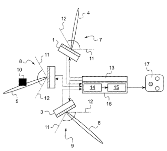
According to Figure 1 a proximity warning system comprises
six basic components, namely a right hand radar unit 1, a forward
radar unit 2 and a left hand radar unit 3. Each of said radar units
1-3 emit a respective radar beam 4-6 in a horizontal direction
scanning predefined regions 7-9 for any obstacles 10 in between
angularly separated flanks 11, 12. Each of said radar units 1-3 are
connected to a processor 13 for radar/rotor synchronization of
each of said radar units 1-3. Signals from each of said radar units
1-3 are fed to a filter 14 and consequently to an analysis unit 15 of
an information processing unit 16. The information processing unit
16 feeds data to a display instrument 17.
The radar units 1-3 are fixed respectively and the associated
radar beams 4-6 are directed inside their respective scanning
region electronically without any mechanical movement of an
antenna or other parts.
Any reflections from an obstacle 10 detected by one or more
of the radar units 1-3 are transmitted to and computed with
associated radar electronics and transmitted to the information
processing unit 16 including data regarding beam direction as well
as the distance of the obstacle. The transmission from the radar
units 1-3 to the information processing unit 16 can be performed
either as a transmission by wire or wireless by radio transmission.
The information processing unit 16 provides amongst others
two functions:
1. Filtering out of all obstacle information which are
caused by any helicopter components, e.g. by the tail boom, by
different antennas or wing parts.
CA 02795752 2012-11-15
2. Analysis
of the resulting information and preparation of
the information for transmission to the display instrument
The display instrument 17 is converting any warning
information from the information processing unit 16 into visual
5 information
and optionally aural and/or haptic/tactile information. A
warning to the pilot is submitted via the display instrument 17 only
in case an obstacle 10 has been identified within a predefined
proximity of the helicopter.
The processor for radar/rotor synchronization 13 senses a
10 reference point during the rotation of the rotor in order to
synchronize the scanning of the radar units 1,...3 to any gaps
between turning rotor blades. The processor for radar/rotor
synchronization 13 provides to the radar units 1,...3 the timing
signal for the start of the scanning process. The scanning is
finished before the next rotor blade could interfere with the radar
beam.
According to Figures 2a, 2b corresponding features are
referred to with the references of Fig. 1. Three radar units 1-3 are
integrated directly into the structure of a helicopter 22, close to a
main rotor head 20 in a cowling 21 of said helicopter 22. An
antenna (not shown) of the forward radar unit 2 is directed to the
forward direction of the helicopter 22. The antennas (not shown) of
the radar units 1 and 3 are respectively directed plus and minus
120 with respect to the antenna of the forward radar unit 2. Thus
the left hand radar unit 3 is scanning the half- backwards region 9
and the right hand radar unit 1 is scanning the half-backwards
region 7.
With scanning regions 7-9 of at least 120 for each radar unit
1-3, the proximity warning system covers horizontally 360 around
CA 02795752 2012-11-15
11
the helicopter 22. Each radar unit 1-3 has a vertical beam width
23, 24, i.e. beam widths in elevation of at least 4 till up to 40 .
According to Figures 3a-4b corresponding features are
referred to with the references of Fig. 1-2b. All radar units 1-3 are
integrated with any cabling (not shown) into a torus like, special
housing 25, close to the rotor head 20. The housing 25 can be
fixed below the rotor head 20 on the roof top structure of the
helicopter 22 (not shown) or, as shown in Figure 3, the housing 25
can be mounted on a non-rotating standpipe 28 on top of the rotor
head 20. The standpipe 28 is conducted through a hole in the rotor
head 20 and the gearbox and fix-joined with the structure of the
helicopter 22.
The housing 25 is constructed with a joint 26 and a closure
27 for the sensor housing 25. The closed housing 25 integrates the
radar units 1-3. The opened housing 20 allows removal of the
radar units 1-3.
According to Figure 5 corresponding features are referred to
with the references of Fig. 1-4b. Synchronizing e. g. the horizontal
scanning radar beam 4 with the rotation 52 around rotor head 20 of
any of the rotor blades 29, 30 is effected by a synchronization
signal sent from the processor for rotor/radar synchronization 13 to
e. g. radar unit 1 when the corresponding scanning region 7 is
available for scanning, i.e. any of the rotor blades 29, 30 do not
shade the concerned scanning region 7. The rotor blades 29, 30 do
not shade the concerned scanning region 7 as long as said rotor
blades 29, 30 are outside a current scanning angle 53 of the
horizontal scanning radar beam 4. Alternatively synchronization
may be spared by "ignoring" all obstacles 10 which are within the
range of the rotor radius. Thus any obstacle recognition according
to this alternative would start only at a distance of about 50% of
CA 02795752 2012-11-15
12
the rotor diameter, e.g. at about 5 m distance, from the radar units
1-3.
According to Figures 6a, 6b corresponding features are
referred to with the references of Fig. 1-5. Any of the radar units 1-
3 comprise an electronically scanning radar antenna 33, radar
electronics 34 with a signal processing section (not shown),
interface electronics 35 for the preparation of the radar data for
transfer to the information processing unit 16 and a radar
transparent radome cover 36 to protect the antenna 33 against
environmental impact. The radome cover 36 can have a curved
shape (Fig. 6a) or a flat shape to cover the antenna 33 (Fig 6b).
The radome cover 36 is made of a radar transparent plastic,
which has been plasma-treated in order to provide a nanostructure
to its outer surface. The nanostructure prevents any icing of the
radome 36 even at very low temperatures (down to -30 C).
According to Figure 7 corresponding features are referred to
with the references of Fig. 1-6b. The setting of the respective
horizontal scanning regions 7-9 of the radar units 1-3 takes into
account a maximum of vertically upward bend 39 and vertically
downward bend 40 of the rotor blades 29-32 relative to the rotor
head 20. In order to allow assessment of any rotor strike risks at
least at a distance of one rotor diameter an upper rotor plane 37
as well as a lower rotor plane 38 should be inside the vertical
beam width 23, 24 of the radar units 1-3.
According to Figure 8 corresponding features are referred to
with the references of Fig. 1-7. An adequate overlap of the
scanning regions 7, 9 of two adjacent radar units 1, 3, each having
a scanning amplitude of more than 120 , allows reduction of any
blind regions 41, 42, 43 of the proximity warning system. The left
hand and right hand radar sensors 1 and 3 each provide different
CA 02795752 2012-11-15
13
blind regions at an empennage 44 and at a casing 45 for a tail
rotor. The right hand radar sensor 1 provides blind regions 46, 47
at the empennage 44 and a blind region 48 at the casing 45 for the
tail rotor. The left hand radar sensor 3 provides blind regions 49,
50 at the empennage 44 and a blind region 51 at the casing 45 for
the tail rotor. The combination of both overlapping scanning
regions 7, 9 of the radar sensors 1 and 3 results in smaller blind
spot regions 41, 42, 43 compared to the blind regions 46-51
resulting from the individual radar sensors 1 and 3.
CA 02795752 2012-11-15
14
Reference List
1 right hand radar unit
2 forward radar unit
3 left hand radar unit
4-6 radar beam
7-9 scanning regions
obstacle
11-12 flanks
13 processor
10 14 filter
analysis unit
16 information processing unit
17 display instrument
rotor head
15 21 cowling
22 helicopter
23-24 vertical beam width
housing 25
26 joint 26
20 27 closure
CA 02795752 2012-11-15
28 non-rotating standpipe
29-32 rotor blades
33 radar antenna
34 radar electronics
5 35 interface electronics
36 radome cover
37 upper rotor plane
38 lower rotor plane
39 upward bend
10 40 downward bend
41-43 blind regions
44 empennage
45 casing
46-51 blind regions
15 52 direction of rotation of rotor
53 current scanning angle