Note: Descriptions are shown in the official language in which they were submitted.
CA 02795759 2014-05-27
PNEUMATIC DOOR SEAL SYSTEMS AND METHODS
FIELD
[0001] The present disclosure relates to pneumatic door seal systems,
apparatus and
methods.
BACKGROUND
[0002] Within the last few years the conservation of energy and
corresponding reduction in
air pollution as a result of heavy duty diesel powered trucks and refrigerated
trailers has been a
major topic. Many jurisdictions currently require reductions in energy use and
air pollution by
trucks and trailers relating to tractor idling as well as operation of diesel
powered refrigeration
units when being loaded, unloaded, or in standby mode at warehouses, loading
docks, stores, and
other general parking areas.
[0003] One important area for efficiency gains is the sealing capability of
roll-up type doors
on refrigerated trailers. By nature of construction, these devices need to
have a space or
clearance between segments of the door, i.e., door panels, and have relatively
low resistance at
the perimeter for them to operate properly. These roll-up type doors are less
efficient from a
BTU retention standpoint than swing-type doors. Additionally, forces created
by the
refrigeration unit push air against the door as it is used as a "bulkhead" to
stop air and can create
cause separate between the panels. Externally, a low pressure condition is
created when the
trailer is running down the road directly behind the trailer and in front of
the door assisting in
creating air loss at the joints of the door.
[0004] In current roll-up doors, the perimeter only has a passive seal,
which can easily be
displaced by the pressure exerted by the air flow from the refrigeration unit.
Thus, there is a
need for seal apparatus that can actively and effectively seal roll-up doors.
There is a further
need for seal apparatus and methods to effectively seal roll-up door
assemblies on trailers. There
also remains a need for a seal apparatus that can actively and effectively
seal roll-up doors and
can be integrated and used with trailers, particularly refrigerated trailers.
1
CA 02795759 2014-05-27
SUMMARY
[0005] The present disclosure, in its many embodiments, alleviates to a
great extent the
disadvantages of known door seals by providing an elastic membrane that
expands when
pressurized air is introduced into it for the purposes of creating a seal
and/or applying pressure
preventing movement of the door panels. The design is such that the deployment
of the seal aids
in keeping the panels from separating. Thus, in the case of a refrigerated
trailer, embodiments
improve thermal capacity, and in the case of a dry van, improve the door's
ability to prevent
water ingress at all joints. The seal may be deployed by a manual or
electrically-manipulated
valve. Further it can also be automatically deployed using the supply line
available on trailers
equipped with air brakes. The membrane could be deployed on equipment without
supply air
available by providing a separate air supply source not intended for braking
purposes.
[0006] In exemplary embodiments, a door sealing system comprises a roll-up
door assembly
and a pneumatic seal apparatus. The roll-up door assembly includes at least
one door panel. The
at least one door panel may comprise a plurality of door panels. The pneumatic
seal apparatus is
located adjacent the at least one door panel and includes an elastic membrane
defining a channel
therethrough and a base member fixedly attached to the elastic membrane via a
neck portion.
The pneumatic seal apparatus may comprise a header seal, a pneumatic gasket,
and a door post
seal, which may be integrally formed or three separate portions. The elastic
membrane, the base
member, and the neck portion may be integrally formed. The elastic membrane
may be made of
one or more of: fluoroelastomer, polyether urethane, styrene butadiene,
epichlorohydrin, EPDM,
silicone, butyl, nitrile, neoprene, or natural rubber.
[0007] The elastic membrane is expandable by injection of pressurized air
such that an
expanded membrane applies outward force against the door panel to seal the
roll-up door
assembly. The system may further comprise a valve to regulate the flow of
pressurized air into
the channel. In exemplary embodiments, the pressurized air is supplied from a
trailer supply
line. The trailer supply line may be fluidly connected to a brake release. The
pressurized air
may be supplied from a trailer air reservoir via a regulator, and the air may
be pressurized by a
refrigeration unit.
2
CA 02795759 2014-05-27
[0008] Exemplary embodiments include a sealing system for a trailer door,
comprising a
trailer and a pneumatic seal apparatus. The trailer has an air supply line and
a roll-up door
assembly, and the roll-up door assembly includes at least one door panel. The
door panel may
comprise a plurality of door panels. The trailer supply line may be fluidly
connected to a brake
release. The sealing system may further comprise a refrigeration unit fluidly
connected to the
trailer supply line wherein the air is pressurized by the refrigeration unit.
The pneumatic seal
apparatus is located adjacent the at least one door panel and includes an
elastic membrane
defining a channel therethrough and a base member fixedly attached to the
elastic membrane via
a neck portion. The pneumatic seal apparatus may comprise a header seal, a
pneumatic gasket,
and a door post seal, which may be integrally formed or three separate
portions. The elastic
membrane, the base member, and the neck portion may integrally formed. The
elastic membrane
is expandable by injection of air pressurized by the refrigeration unit, the
air traveling to the
channel via the air supply line such that an expanded membrane applies outward
force against
the door panel to seal the roll-up door assembly. The pressurized air may be
supplied from a
trailer air reservoir via a regulator.
[0009] Exemplary embodiments include methods of sealing a trailer door
comprising
injecting pressurized air into a pneumatic seal apparatus. The pneumatic seal
apparatus is
located adjacent the at least one door panel and has an elastic membrane
defining a channel
therethrough such that an expanded membrane applies outward force against a
door panel to seal
a roll-up door assembly. The methods may further comprise pressurizing the air
using a
refrigeration unit. Exemplary methods further comprise supplying the air from
a trailer air
reservoir via a regulator. The methods may further comprise supply the air via
a trailer supply
line, and the trailer supply line may be fluidly connected to a brake release.
The methods may
further comprise regulating flow of pressurized air into the channel using a
valve.
[0010] Accordingly, it is seen that pneumatic sealing systems, apparatus
and methods are
provided that improve the sealing and thermal efficiencies of roll up doors,
provide added
security and reduce damage associated with vibration from traveling over the
road. These and
other features and advantages will be appreciated from review of the following
detailed
description, along with the accompanying figures in which like reference
numbers refer to like
parts throughout.
3
CA 02795759 2014-05-27
BRIEF DESCRIPTION OF THE DRAWINGS
[0011] The foregoing and other objects of the disclosure will be apparent
upon consideration
of the following detailed description, taken in conjunction with the
accompanying drawings, in
which:
[0012] FIG. 1 is a perspective view of an embodiment of a trailer in
accordance with the
present disclosure;
[0013] FIG. 2 is a perspective view of an embodiment of a sealing system in
accordance with
the present disclosure;
[0014] FIG. 3 is a perspective view of an embodiment of a sealing system in
accordance with
the present disclosure;
[0015] FIG. 4 is a perspective view of an embodiment of a seal track in
accordance with the
present disclosure;
[0016] FIG. 5A is a perspective view of an embodiment of a pneumatic seal
apparatus in
accordance with the present disclosure;
[0017] FIG. 5B is a cross-sectional view of the pneumatic seal apparatus of
FIG. 5A;
[0018] FIG. 6 is a schematic view of an embodiment of a sealing system in
accordance with
the present disclosure;
[0019] FIG. 7 is a schematic view of an embodiment of a sealing system in
accordance with
the present disclosure;
[0020] FIG. 8 is a cross-sectional view of an embodiment of a sealing
system in accordance
with the present disclosure;
[0021] FIG. 9A is a cross-sectional view of an embodiment of a sealing
system in
accordance with the present disclosure; and
[0022] FIG. 9B is a cross-sectional view of an embodiment of a sealing
system in accordance
with the present disclosure.
4
CA 02795759 2014-05-27
DETAILED DESCRIPTION
[0023] In the following paragraphs, embodiments will be described in detail
by way of
example with reference to the accompanying drawings, which are not drawn to
scale, and the
illustrated components are not necessarily drawn proportionately to one
another. Throughout
this description, the embodiments and examples shown should be considered as
exemplars,
rather than as limitations of the present disclosure. As used herein, the
"present disclosure"
refers to any one of the embodiments described herein, and any equivalents.
Furthermore,
reference to various aspects of the disclosure throughout this document does
not mean that all
claimed embodiments or methods must include the referenced aspects.
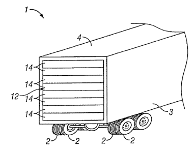
[0024] Referring to FIGS. 1-4, a trailer 1, commonly referred to as a semi-
trailer or van, has
wheels 2, side walls 3, a roof 4, and a roll-up door assembly 12 that includes
at least one door
panel 14. The roll-up door assembly 12 typically has space or clearance
between the panels 14,
or segments, of the door assembly. Inside views of the trailer 1, as in FIGS.
2 and 3, illustrate
pneumatic seal apparatus 16. Pneumatic seal apparatus 16 is arranged around
the perimeter of
trailer doorway 18 so as to be adjacent to at least one of the door panels 14
and, in exemplary
embodiments, adjacent the full roll-up door assembly 12. More particularly,
pneumatic seal
apparatus 16 is disposed in seal track 20, which extends around the perimeter
of trailer doorway
18 and is sized to receive the seal apparatus 16.
[0025] The pneumatic seal apparatus 16 can be configured as a three-piece
design, as shown
in FIG. 2, or as a single-piece design joined together at the corners, as
shown in FIG. 3. An
embodiment of a three-piece design of pneumatic seal apparatus 16 comprises
header seal 16a
and door post seals 16b, 16c. A pneumatic gasket 17 may also be provided to
fill any
irregularities between the seals 16a, 16b, 16c and the roll-up door assembly
12. As described in
more detail herein, trailer supply line 30 may supply air to the pneumatic
seal apparatus 16.
[0026] Exemplary embodiments of a pneumatic seal apparatus 16 are shown in
more detail
in FIGS. 5A and 5B. Pneumatic seal apparatus 16 includes an elastic membrane
22 defining a
channel 24 therethrough. As discussed in more detail herein, the elastic
membrane 22 expands
when the channel 24 receives pressurized air. The elastic membrane 22 may be
made of any
lightweight, strong, elastic material including fluoroelastomer, polyether
urethane, styrene
butadiene, epichlorohydrin, EPDM, silicone, butyl, nitrile, neoprene, natural
rubber, or any
CA 02795759 2014-05-27
combination of such materials. In exemplary embodiments, the pneumatic seal
includes a base
member 26, which is sized to fit into seal track 20. A neck portion 28 may be
located between
elastic membrane 22 and base member 26 and may connect the elastic membrane 22
to the base
member 26. It should be noted that a variety of different pneumatic seal
arrangements could be
used, so long as an elastic, expandable material defines a channel for
injection of air.
[0027] In exemplary embodiments, the pneumatic seal apparatus 16 of door
sealing system
receives air 32 from the trailer's air supply line 30. The trailer supply line
30 may be fluidly
connected to the trailer parking brake release 34 such that air 32 from the
supply line 30 joins the
trailer supply line system at the brake release 34. The supply line 30 is
coupled to activator /
pressure protection valve 36 and regulator 38. Ultimately, the supply line 30
is fluidly connected
to the pneumatic seal apparatus 16. An example of this embodiment is
illustrated in FIG. 6.
[0028] Another exemplary embodiment, shown in FIG. 7, supplies air 32 to
the pneumatic
seal apparatus from the trailer's air reservoir 40, which receives air from an
external air supply
41. A supply line 30 is fluidly connected to the air reservoir 40 and extends
to control valve 42
and then regulator 38, which serves to regulate the pressure of air 32.
Regulator 38 may be
configured to allow air flow at a pre-determined pressure or within a pre-
determined pressure
range and automatically cut off the flow of air 32 if the pressure is outside
the pre-determined
range. Ultimately, the supply line 30 is fluidly connected to the pneumatic
seal apparatus 16. It
should be noted that the control valve 42 could be manually operated or
automatically controlled
electrically, e.g., an electric solenoid valve, or via wireless communication.
The trailer's
refrigeration unit 44 could be fluidly connected to the supply line 30 to
provide pressure to air
32. In operation, the user first closes the roll-up door assembly 12, which
may be accomplished
by moving the door assembly 12 downward in door track 13, the door track 13
optionally
engaged by rollers 21, mounted to the door via roller mounts 23 mounting the
roller axle posts 25
(see FIG. 8). The air 32 originates either from an air source 41 external to
the trailer 1 or from
the trailer's air reservoir 40. The air 32 travels through the trailer supply
line 30 and may pass
through the trailer parking brake release mechanism 34. From the brake release
34, the air 32
passes through pressure protection valve 36 and regulator 40 to the pneumatic
seal apparatus 16.
This could be an automatic process. Alternatively, in a manual process, the
air 32 originating
from the air reservoir 40 could bypass the brake release 34 and pass through
control valve 42 and
6
CA 02795759 2014-05-27
regulator to the pneumatic seal apparatus 16. In either case, the air 32 could
be pressurized by
the refrigeration unit 44.
[0029] When the air 32 enters the pneumatic seal apparatus 16 it fills the
channel 24. As best
seen in FIGS. 8, 9A and 9B, this causes the elastic membrane 22 of the seal
apparatus 16 to
expand. The expanded membrane 22 applies an outward force against at least one
panel 14 of
the roll-up door assembly 12. This outward force or pressure provides a seal
to the roll-up door
assembly 12 and prevents movement of the panels 14 such that the panels 14
press against each
other. As a result, the door assembly 12 is tightly shut.
[0030] To unseal the pneumatic seal apparatus 16 and open the door assembly
12, control
valve 42 may be automatically shut to stop the flow of air 32 to the pneumatic
seal apparatus.
Alternatively, the user could manually shut pressure protection valve 36 to
stop the flow of air
32. With the air flow shut off, as the air 32 exits door post seal 16c it is
not replaced with
additional air flow. This causes channel 24 to empty and the elastic membrane
22 to contract,
removing outward pressure on the roll-up door assembly 12. The panels 14 can
now move and
the door assembly 12 can be opened.
[0031] Thus, it is seen that pneumatic sealing systems and methods are
provided. It should
be understood that any of the foregoing configurations and specialized
components or may be
interchangeably used with any of the apparatus or systems of the preceding
embodiments.
Although illustrative embodiments are described hereinabove, it will be
evident to one skilled in
the art that various changes and modifications may be made therein without
departing from the
scope of the disclosure. It is intended in the appended claims to cover all
such changes and
modifications that fall within their scope.
7