Note: Descriptions are shown in the official language in which they were submitted.
CA 02796283 2012-10-11
WO 2011/130183 PCT/US2011/031986
APPARATUS, SYSTEM AND METHOD FOR DETECTION AND DELIVERY
OF A MEDICINAL DOSE
CROSS REFERENCE TO RELATED APPLICATIONS
[0001] This application claims the benefit of US Provisional Patent
Application Ser. No.
61/322,893, filed April 11, 2010 and entitled "System and Method for Delivery
of an Inhalable
Dose"; US Provisional Patent Application Ser. No. 61/357,506, filed June 22,
2010 and entitled
"System and Method for Detection of Delivery of an Inhalable Dose"; and US
Provisional Patent
Application Ser. No. 61/373,803, filed August 13, 2010 and entitled "System
and Method for
Delivery and Detection of an Inhalable Dose"; and US Provisional Patent
Application Ser. No.
61/377,072, filed August 25, 2010 and entitled "System and Method for Patient
Access Port
Reporting" each of which is hereby incorporated by reference in its entirety.
FIELD OF THE INVENTION
[0002] The present invention is related to electronic systems and, more
specifically, to
electronic systems for determining and confirming delivery of a dose of
medication.
INTRODUCTION
[0003] Commonly used medication delivery systems include a chamber for storing
the dose.
As needed, a patient will use the system to take a dose of the medication.
However, there is no
accurate way of determining if the patient took the dose or when the patient
took the dose. For
example, there are delivery systems that track the number of times a dose was
dispensed or
delivered. However, the delivery systems lack the ability to determine if and
when the doses
were delivered to a patient. For example, a patient may discharge the delivery
system several
times in a short period of time to give the appearance that several doses were
taken over a
period of time. There are some delivery systems that time-stamp the delivery,
but lack the
ability to determine if the patient actually received the dose as required.
For example, the
patient may discharge the delivery system over a long period of time without
actually taking or
inhaling the dose to give the appearance that the doses were taken regularly
over a longer
period of time. Thus, these delivery systems are not capable of determining if
the patient
actually received the dose. Furthermore, there is no accurate way of
determining if the dose
that was delivered was actually delivered to the patient as intended. For
example, the delivery
1
CA 02796283 2012-10-11
WO 2011/130183 PCT/US2011/031986
system may have been discharged by someone other than the patient.
Additionally, in some
instances, the delivery systems may have been accidentally discharged.
[0004] Therefore, what is needed is a system and method for determining if a
medicinal dose
was delivered to a patient as intended as well as tracking the delivery time
and thereby
providing an accurate determination of when the patient actually received the
dose.
SUMMARY
[0005] In accordance with aspects of the systems and teaching of the present
invention, a
system and method are provided that track the delivery time of a medicinal
dose to the patient
as well as providing confirmation that the patient actually received the dose.
The system
includes a detector and an apparatus. The detector is communicatively coupled
to the user and
is capable of detecting a current flow through the user's body. The current
flow is produced
when the user makes contact with the apparatus. The apparatus includes at
least two contact
areas connected to a power source such that a circuit and, hence, a current
path is completed
through the user's body as the user makes contact with each of the two contact
areas and a
current flow is detected by the detector, which is coupled to the user.
[0006] In another aspect, the system includes a detector and an apparatus with
an acoustic
unit. The detector is communicatively coupled to the user and is capable of
detecting a current
flow through the user's body as well as acoustic information produced by the
acoustic unit. The
current flow is produced when the user makes contact with the apparatus. The
apparatus
includes at least two contact areas connected to a power source such that a
circuit and, hence,
a current path is completed through the user's body as the user makes contact
with each of the
two contact areas and a current flow is detected by the detector, which is
coupled to the user.
Notwithstanding the claims, the present invention is also defined by the
following clauses:
1. An apparatus for delivering a dose to a user and track the timing of the
delivery of the
dose, the apparatus comprising:
a detector configured to couple to the user;
an apparatus, wherein the apparatus comprises:
a housing defining a chamber to store the dose;
2
CA 02796283 2012-10-11
WO 2011/130183 PCT/US2011/031986
at least two contact areas positioned on the housing wherein the contact areas
are near or on the exterior of the housing and the at least two contact areas
are electrically
isolated from each other;
a power source secured to the housing and including a positive phase terminal
and a negative phase terminal, wherein at least one contact area is
electrically coupled to the
positive phase terminal and at least one other contact area is electrically
coupled to the negative
phase terminal; and
wherein a current path is completed through the user's body as the user makes
contact with each of the two contact areas and current flow is detected by the
detector that is
coupled to the user.
2. The apparatus of clause 1, wherein the dose is an inhalable dose or
wherein the dose is an ingestible dose.
4. The apparatus of clause 1 or 2 , further comprising a control module
electrically
connected between the power source and one of the at least two contact areas,
wherein the
control module is configured to control information associated with the
apparatus, preferably
wherein the control module is electrically coupled to the at least two contact
areas and to both
terminals of the power source, for example wherein the control module is
configured to vary the
conductance of the current path to encode information in the current flow,
preferably wherein
the apparatus further comprises a transceiver electrically coupled to the
control module wherein
information can be transmitted and/or received from the apparatus to the
detector other than
through the current flow.
5. The apparatus of clause 4, wherein the detector comprises:
a hermetically sealed housing;
a power source secured within the housing;
a processor electrically coupled to the power source and secured within the
housing;
at least one sensing probe secured to the housing wherein the probe is
electrically
coupled to the processor so that the processor detects physiological
parameters associated with
the user and the current flow through the user; and
a memory unit electrically coupled to the processor and secured to or within
the housing
to store data;
3
CA 02796283 2012-10-11
WO 2011/130183 PCT/US2011/031986
wherein the transceiver is electrically coupled to the processor and secured
within the
housing to receive and decode information transmitted from the apparatus.
6. The apparatus of clause 4 or 5 wherein the detector is configured to be
implanted within
the user's body or on the user's skin, wherein the probe is at least partially
exposed to contact
the user's tissue or skin.
7. The apparatus of any of the clauses 4-6 wherein the transceiver is
communicatively
coupled to a data management center to provide two-way wireless communication
of the data
from the detector to the data management center.
8. The apparatus according to any of the preceding clauses further comprising
an acoustic
unit secured to the housing, preferably wherein the acoustic unit comprises:
a support layer comprising an adhesive layer on one surface for securing the
acoustic
unit to the apparatus;
a vibration detection unit secured to the support layer to detect acoustic
information
produced by the apparatus and the user inhaling through the apparatus and
produce a detection
signal;
a controller secured to the support layer and in communication with the
vibration
detection unit, wherein the controller receives the detected signal from the
vibration detection
unit and produces a digital signal representing the detected signal;
a sound generation unit secured to the support layer and in communication with
the
controller, wherein the sound generation unit receives the digital signal and
produces the
acoustic signal; and
a top layer secured to the support layer to define a cavity that contains and
protects the
vibration unit, the controller, and the sound generation unit within the
cavity,
wherein the acoustic signal represents information associated with the
inhalable dose
being loaded into the chamber and the user inhaling through the apparatus and
wherein the
acoustic signal is detected by the detector to confirm delivery of the dose.
9. The apparatus of clause 8, wherein the acoustic unit is coupled to a
control module
secured to the housing.
4
CA 02796283 2012-10-11
WO 2011/130183 PCT/US2011/031986
10. The apparatus of clause 8 or 9, wherein the acoustic unit provides an
activation signal to
the control module upon detection of a vibration representing the loading of a
medication into
the chamber.
11. The apparatus of any of the clauses 8-11 wherein a sound of the dose being
loaded into
the chamber activates the control module and wherein a current path is
completed through the
user's body as the user makes contact with each of the contact areas
indicating that the user is
about the receive a dose of a medication.
12. The apparatus of any of the clauses 8-12 wherein the acoustic unit
provides an
activation signal to the control module and the control module records
acoustic information
associated with the user inhaling, wherein the information is provided to the
control module
through the acoustic detector.
13. The apparatus according to any of the preceding clauses 8-12 wherein the
control
module provides a unique time stamp associated with the delivery of the dose
and wherein the
control module receives an identifier signal that is associated with the user
wherein the
combination of the time stamp and the identifier signal confirms deliver of
the dose to the user.
14. The apparatus according to any of the preceding clauses 4-13 wherein the
transceiver
is electrically coupled to the control module and secured to the housing and
wherein the
transceiver allows the apparatus to transmit and/or receive information
associated with the
delivery of the dose to the user.
15. The apparatus of clause 14, wherein the transceiver comprises at least one
of an optical
transmitter module for optical communication and a wireless transmitter module
for wireless
communication.
16. The apparatus of clauses 14 or 15, wherein the transceiver encodes
information from
the memory unit and transmits that information to a system external to the
apparatus.
17. The apparatus of clause 16, wherein the transceiver sends an activation
signal to the
external system once a circuit is completed through the user's body wherein
the activation
signal is an indicator that the user is prepared to initiate delivery of the
dose.
CA 02796283 2012-10-11
WO 2011/130183 PCT/US2011/031986
18. The apparatus according to any of the preceding clauses 8-17 wherein the
acoustic unit
is activated by a processor to detect acoustic information from the user's
lungs upon the
acoustic unit receiving the activation signal from the apparatus.
19. A system to deliver a dose to a user and to confirm delivery of the dose,
the system
comprising an apparatus preferably according to any of the preceding clauses
and a detector
configured to couple to the user.
20. A system according to clause 21 wherein the detector includes a capacitive
coupler.
21. A system according to clauses 19 or 20 further comprising,
a housing defining a chamber to store the dose;
a power source secured to the housing and including a positive terminal and a
negative
terminal, wherein the power source comprises an isolating source that produces
a carrier wave;
a control module electrically coupled to the power source, wherein the control
module
alters the characteristics of the isolating source to encode information in
the carrier wave; and
at least two areas positioned on the housing wherein one area is a partially
exposed
contact area and one area is capacitive coupled area, wherein the two areas
are electrically
isolated from each other,
wherein one output of the isolating source is coupled to the contact area and
the other
output of the isolating source is coupled to the capacitive coupled area,
wherein the contact area is touched by the user and the capacitive coupled
area is
capacitively coupled to the capacitive coupler worn by the user, and
wherein a portion of the carrier wave's path is through the user's body using
the contact
area and a portion of carrier wave's path is through capacitive conductance
using the capacitive
coupling between the capacitive coupled area and the capacitive coupler worn
by the user.
22. The system of clause 21, wherein the housing defines an aperture to
generate an
acoustic wave as the user inhales through the apparatus and wherein the
detector further
comprises an acoustic unit for detecting acoustic wave associated with the
user inhaling through
the apparatus, which acoustic waves traveling through the user's body and
through the air,
wherein the acoustic unit correlates the acoustic wave through the user's body
and the acoustic
wave through the air to confirm delivery of the dose to the user.
6
CA 02796283 2012-10-11
WO 2011/130183 PCT/US2011/031986
23. The system according to any of the clauses 19-22 further comprising a
vibration
detection unit to detect acoustic information and produce a detection signal;
a controller in communication with the vibration detection unit, wherein the
controller
receives the detection signal from the vibration detection unit and produces a
digital signal
representing the detection signal;
a sound generation unit secured to the support layer and in communication with
the
controller, wherein the sound generation unit receives the digital signal and
produces an
acoustic signal that indicates delivery of the dose.
24. An apparatus for detection of delivery of a dose to a user, the apparatus
comprising:
a vibration detection unit to detect acoustic information and produce a
detection signal;
a controller in communication with the vibration detection unit, wherein the
controller
receives the detection signal from the vibration detection unit and produces a
digital signal
representing the detection signal;
a sound generation unit secured to the support layer and in communication with
the
controller, wherein the sound generation unit receives the digital signal and
produces an
acoustic signal that indicates delivery of the dose.
25. The apparatus of clause 24, further comprising a transceiver in
communication with the
controller, wherein the transceiver receives the digital signal and
communicates with a wireless
apparatus to indicate the inhalation event has occurred.
26. The apparatus of clause 24 or 25, further comprising a transconduction
unit in
communication with the controller, the transconduction unit comprising:
at least two contact areas electrically isolated from each other and
positioned to allow
contact with each of the contact areas;
a power source, wherein at least one contact area is electrically coupled to
one terminal
of the power source and at least one other contact area is electrically
coupled to another
terminal of the power source,
wherein a current path is completed through the user's body to allow current
flow as the
user makes contact with each of the two contact areas and current flow is
detected by the
controller.
7
CA 02796283 2012-10-11
WO 2011/130183 PCT/US2011/031986
27. The apparatus of clause 26, wherein the transconduction unit further
comprises a control
module electrically connected between the power source and one of the at least
two contact
areas, wherein the control module is configured to encode information in the
current flow.
28. A method for recording the time that a dose is taken by a user, the method
comprising
the steps of:
activating a power module of an apparatus when the user makes contact with the
exterior of the apparatus in such a manner to complete a circuit to allow for
current flow
between two terminals of the power module and through the user's body;
altering the current characteristics through changes in a conductance of the
circuit that is
formed through the user's body using a conductance control module;
detecting the current characteristics through the user's body using a
detector, wherein
the current characteristics comprises information associated with at least one
of the apparatus
and the dose; and
recording the timing of delivery of the inhalable dose.
29. The method of clause 28, comprising:
generating an acoustic signal using an acoustic unit; and
detecting the acoustic signal using an acoustic unit, wherein the acoustic
signal
comprises information associated with delivery of the dose to the user.
30. Use of a system or apparatus according to any of the preceding clauses for
delivering a
dose to a user and tracking the timing of the delivery of the dose, or for
delivering a dose to a
user and confirming delivery of the dose.
BRIEF DESCRIPTION OF THE FIGURES
[0007] The novel features of the various aspects of the present invention are
set forth with
particularity in the appended claims. The various aspects, however, both as to
organization and
methods of operation, are described herein by way of example in conjunction
with the following
figures and corresponding description, where like reference numbers refer to
like elements
throughout.
8
CA 02796283 2012-10-11
WO 2011/130183 PCT/US2011/031986
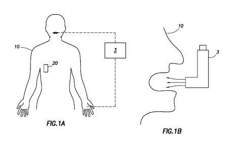
[0008] Fig. 1 A is an illustrative example of a user wearing a detector and
making contact with
an apparatus, which is shown in block diagram form, which delivers an
inhalable dose in
accordance with the teachings of the present invention.
[0009] Fig. 1 B shows one possible physical shape for the apparatus of Fig. 1
A, in accordance
with the teachings of the present invention.
[0010] Fig. 1 C shows one possible physical shape for the apparatus of Fig. 1
A, in accordance
with the teachings of the present invention.
[0011] Fig. 1 D shows one possible physical shape for the apparatus of Fig. 1
A, in accordance
with the teachings of the present invention.
[0012] Fig. 2A is an alternative aspect of the apparatus of Fig. 1 A shown in
block diagram
form and in accordance with the teachings of the present invention.
[0013] Fig. 2B is an alternative aspect of the apparatus of Fig. 1 A shown in
block diagram
form and in accordance with the teachings of the present invention.
[0014] Fig. 3A is an illustrative example of a user wearing a detector and
making contact with
an apparatus, which is shown in block diagram form, which delivers an
inhalable dose in
accordance with the teachings of the present invention.
[0015] Fig. 3B shows another possible physical shape for the apparatus of Fig.
3A comprising
an acoustic unit, in accordance with the teachings of the present invention.
[0016] Fig. 3C shows another possible physical shape for the apparatus of Fig.
3A comprising
an acoustic unit, in accordance with the teachings of the present invention.
[0017] Fig. 3D shows another possible physical shape for the apparatus of Fig.
3A comprising
an acoustic unit, in accordance with the teachings of the present invention.
[0018] Fig. 3E is an illustrative example of a user wearing a detector and
making contact with
an apparatus, which is shown in block diagram form, which delivers an
inhalable dose in
accordance another aspect of the present invention.
[0019] Fig. 3F is a side view illustration of a portion of the apparatus of
Fig. 3E.
9
CA 02796283 2012-10-11
WO 2011/130183 PCT/US2011/031986
[0020] Fig. 4A is an alternative aspect of the apparatus of Fig. 3A comprising
an acoustic unit
shown in block diagram form and in accordance with the teachings of the
present invention.
[0021] Fig. 4B is an alternative aspect of the apparatus of Fig. 3A comprising
an acoustic unit
shown in block diagram form and in accordance with the teachings of the
present invention.
[0022] Fig. 4C is a top view illustration of an acoustic unit that in
accordance with one aspect
of the present invention.
[0023] Fig. 4D is an illustration of an acoustic unit in accordance with one
aspect of the
present invention.
[0024] Fig. 4E is an illustration of an acoustic unit in accordance with one
aspect of the
present invention.
[0025] Fig. 5A is an illustrative example of a user wearing a detector and
making contact
with an apparatus, which is shown in block diagram form in accordance with the
teachings
of the present invention.
[0026] Fig. 5B shows one possible physical shape for the apparatus of Fig. 5A
with an
apparatus electrically connected to contact areas in accordance with the
teachings of the
present invention.
[0027] Fig. 5C shows one possible physical shape for the apparatus of Fig. 5A
with an
apparatus electrically coupled to contact areas in accordance with the
teachings of the present
invention.
[0028] Fig. 5D shows one possible physical shape for the apparatus of Fig. 5A,
with an
apparatus and an acoustic unit, each electrically coupled to contact areas in
accordance with
the teachings of the present invention.
[0029] Fig. 5E shows an acoustic unit in accordance with one aspect and
teaching of the
present invention.
[0030] Fig. 5F shows an acoustic unit in accordance with another aspect and
teaching of the
present invention.
CA 02796283 2012-10-11
WO 2011/130183 PCT/US2011/031986
[0031] Fig. 6A is the apparatus of Figs. 5B, 5C, and 5D in block diagram form
and in
accordance with one aspect of the teachings of the present invention.
[0032] Fig. 6B is the apparatus of Figs. 5B, 5C, and 5D in block diagram form
and in
accordance with another aspect of the teachings of the present invention.
[0033] Fig. 7A is an illustration of the opening of the apparatus of Figs. 1A,
3A, 5A in
accordance with another aspect of the present invention, wherein a diaphragm
is positioned
near the opening of the apparatus through which the inhalable dose is
dispensed.
[0034] Fig. 7B is an illustration of the diaphragm of the apparatus of Fig.
7A, wherein the
diaphragm portions are parted as the dose is inhaled by the user such that a
beam of light is
interrupted and the interruption is detected.
[0035] Fig. 7C is an illustration of the diaphragm of the apparatus of Fig. 7A
being parted as
the dose is inhaled by the user such that a flexing motion and parting of the
diaphragm portions
cause an interruption in a connection.
[0036] Fig. 8 is a block diagram illustration of any one of the detectors of
Figs. 1 A, 3A, 5A.
[0037] Fig. 9 is a block diagram illustration of a processor of Fig. 8.
[0038] Fig. 10 shows an example of a user wearing a detector and making
contact with an
apparatus as the user inhales to receive an inhalable dose in accordance with
the teachings of
the present invention.
[0039] Fig. 11 shows an access apparatus with the ability to record the timing
of certain
events associated with maintaining the access apparatus.
[0040] Fig. 12A is an illustrative example of a user wearing a detector and
making contact
with an apparatus, which is shown in block diagram form, which delivers a
medicinal dose in
accordance with the teachings of the present invention.
[0041] Fig. 12B shows one aspect of the medication delivery apparatus of Fig.
12A for
delivering an individual pill from a reservoir of pills, in accordance with
the teachings of the
present invention.
11
CA 02796283 2012-10-11
WO 2011/130183 PCT/US2011/031986
[0042] Fig. 12C illustrates one aspect of the medication delivery apparatus of
Fig. 12A for
delivering an individual pill from a reservoir of pills, in accordance with
the teachings of the
present invention.
[0043] Fig. 12D illustrates one aspect of the medication delivery apparatus of
Fig. 12A for
delivering an individual pill from a reservoir of individually sealed pills,
in accordance with the
teachings of the present invention.
[0044] Fig. 13A is an illustrative example of a user wearing a detector and
making contact
with an apparatus, which is shown in block diagram form, which delivers a
medicinal dose in
accordance with the teachings of the present invention.
[0045] Fig. 13B illustrates one aspect of the medication delivery apparatus of
Fig. 13A for
delivering an individual pill from a tape comprising a plurality of pills
sealed therein, in
accordance with the teachings of the present invention.
[0046] Fig. 13C illustrates one aspect of the tape comprising a plurality of
pills sealed within a
package that can be coiled up and inserted inside a chamber of the apparatus
of Fig. 13A, in
accordance with the teachings of the present invention.
[0047] Fig. 13D illustrates one aspect of the medication delivery apparatus of
Fig. 13A for
delivering an individual pill from a tape comprising a plurality of pills
sealed therein, in
accordance with the teachings of the present invention.
[0048] Fig. 13E is a top view of a tape delivery mechanism for liquid medicine
delivery of one
aspect of the medication delivery apparatus of Fig. 13A, in accordance with
the teachings of the
present invention.
[0049] Fig. 13F is a side view of a tape delivery mechanism for liquid
medicine delivery of one
aspect of the medication delivery apparatus of Fig. 13A, in accordance with
the teachings of the
present invention.
[0050] Fig. 14A is an illustrative example of a user wearing a detector and
making contact
with an apparatus, which is shown in block diagram form, which delivers a
medicinal dose in
accordance with the teachings of the present invention.
12
CA 02796283 2012-10-11
WO 2011/130183 PCT/US2011/031986
[0051] Fig. 14B illustrates one aspect of the medication delivery apparatus of
Fig. 14A for
delivering an individual pill from a tape comprising a plurality of pills
sealed therein while also
delivering a dose of liquid, in accordance with the teachings of the present
invention.
[0052] Fig. 15A is an illustrative example of a user wearing a detector and
making contact
with an apparatus, which is shown in block diagram form, which delivers a
medicinal dose in
accordance with the teachings of the present invention.
[0053] Fig. 15B illustrates one aspect of the medication delivery apparatus of
Fig. 15A for
delivering an individual does of liquid medication from a bladder, in
accordance with the
teachings of the present invention.
DETAILED DESCRIPTION
[0054] Referring to Fig. 1 A, a user 10 is shown wearing a detector 20 and
making physical
contact with an apparatus 3; the detector 20 and the apparatus 3 are described
in greater detail
hereinbelow. The detector 20 is shown secured at one location on the user's
body and is
communicatively coupled to the user 10 and is capable of detecting a current
flow through the
user's body. However, the scope of various aspects of the present invention is
not limited by the
positioning of the detector 20 on the user's body. The detector 20 may be
secured to any
location on the user's body. In accordance with another aspect of the present
invention, the
detector 20 is secured to the user's clothing. In accordance with yet another
aspect of the
present invention, the detector 20 may be worn by the user in the form of
jewelry, watch,
apparel, etc. In such aspects, the detector 20 may be communicatively coupled
to the
user, e.g., contacting the user, in near physical proximity to the user, in
communicative
proximity to the user, etc.
[0055] In the present illustrated example, the detector 20 is shown as a
detector that is
external to the user's body. In accordance with another aspect of the present
invention, the
detector 20 may be positioned or implanted within the user's body. In yet
another aspect of the
present invention, the detector 20 may be partially implanted within the
user's body. The
externally secured detector 20 of interest includes those that are sized to be
stably associated
with a living subject in a manner that does not substantially impact movement
of the living
subject. As such, the detector 20 may have dimensions that, when secured to
the user 10, will
not cause the user 10 to experience any difference in mobility or movement.
13
CA 02796283 2012-10-11
WO 2011/130183 PCT/US2011/031986
[0056] In accordance with some aspects of the present invention, the detector
20 is
dimensioned such that its size does not hinder the ability of the subject to
physically move. For
example, in one aspect the detector 20 has a small size and may occupy a
volume of space of 5
cm3 or less, such as 3 cm3 or less, including 1 cm3 or less. In another aspect
the detector 20
has a small size and may occupy a volume of space of 25 cm3 or less, such as
12 cm3 or less,
including 5 cm3 or less. In another aspect the detector 20 has a small size
and may occupy a
volume of space of 25 cm3 or less, such as 5 cm3 or less, including 1 cm3 or
less. In
accordance with one aspect of the present invention a receiver (not shown) can
be included in
the apparatus 3. In such instances, the receiver has a chip size limit ranging
from 2 mm2 to 2
cm2.
[0057] The user 10 holds the apparatus 3 in the user's hand and places the
apparatus 3 to the
user's mouth, thereby making contact with the apparatus 3 in at least two
locations, as shown.
In the case of a small child, the parent may hold the apparatus 3. In various
aspects, if the child
makes contact with the parent, then as described hereinbelow, a circuit is
completed through
the parent and child. The apparatus 3 is shown in block diagram form for
clarity of describing
the functionality thereof as well as the components therein. However, the
apparatus 3 can be
made is a variety of shapes according to the various aspects of the present
invention.
[0058] Referring now to Figs. 1 B, 1 C, and 1 D, in accordance with various
aspects of the
present invention, the apparatus 3 can be in a variety of shapes. For example,
Fig. 1 B shows
the apparatus 3 as an upright inhaler with a chamber that is capable of
receiving a pressurized
can that contains multiple and/or single doses, each dose delivered
individually over a period of
time to the user 10. Fig. 1 C shows the apparatus 3 as a single dose inhaler
with a chamber that
is capable of holding one dose. After the single dose is delivered to the user
10, the chamber is
reloaded. Fig. 1 D shows the apparatus 3 as an inhaler capable of providing
continuous delivery
of a dose or delivery of a dose at pre-determined intervals using a motorized
unit 27 that is
associated with a power source. Additional examples and shapes for the
delivery of an
inhalable dose are considered to be within the scope of the present invention.
Thus, according
to various aspects of the present invention, the apparatus 3 can be in various
shapes and dose
delivery set-ups, as shown in Figs. 1 B, 1 C, and 1 D and the scope of the
present invention is not
limited by the actual shape or dose-delivery type or dose-delivery timing of
device.
[0059] In various aspects, the example apparatus 3, may include an acoustic
unit or acoustic
unit in accordance with various aspects of the present invention as shown, for
example, in
14
CA 02796283 2012-10-11
WO 2011/130183 PCT/US2011/031986
connection with apparatus 30 and apparatus 25 as shown in Figs. 3B and 5B,
respectively, and
as described in more detail hereinbelow.
[0060] Referring now to Fig. 2A, the apparatus 3 includes a housing 32, a
power source 34, a
control unit 36, contact areas 38, 40 and a memory unit 42. The housing 32
defines a chamber
44 for holding the inhalable doses. The chamber 44 may also include a chamber
control unit for
controlling dispensing of the dose. The chamber 44 also includes an opening
through which the
inhalable dose is delivered to the patient, as discussed with respect to Fig.
7A hereinbelow. In
accordance with one aspect of the present invention, the housing 32 includes
at least two
contact areas/points 38, 40 positioned at different locations on the housing
32. The location and
position of the contact points 38, 40 or areas are determined by the shape and
design of the
apparatus 3 and in accordance with the various aspects of the present
invention. Multiple
locations for the contact areas 38, 40 are contemplated.
[0061] In accordance with another aspect of the present invention, the contact
areas 38, 40
may include functionality that allow for reading and recording of biometric
information, such as
finger print data. This information may be communicated to the apparatus 3 and
stored therein
for confirmation of the user's identity.
[0062] The contact areas 38, 40 are electrically isolated from each other and
at least partially
exposed or exposable to allow the user 10 to make contact therewith. In one
aspect, the
contact areas 38, 40 may also be coated with a thin dielectric, such as
plastic, and the electrical
communication is accomplished using capacitive coupling through this
dielectric to the user.
Capacitive coupling may be accomplished at signal frequencies greater than
about 20kHz and
in some aspects about 80kHz for good signal-to-noise ratio (SNR, e.g., signal
to ambient noise).
In accordance with one aspect of the present invention, the contact areas 38,
40 are positioned
such that one contact area 38, for example, makes contact with the user's hand
and the other
contact area 40, for example, makes contact with the user's mouth. In
accordance with
alternative aspect of the present invention, additional contact areas may be
added to allow for
secondary contacts with the hand or mouth as well as to accommodate using a
different hand,
such as a left hand grip as well or a right hand grip. Furthermore, additional
contact areas on
the housing 32 can be included to ensure that the apparatus 3 is held
properly. If the contact
areas 38, 40 are covered by dielectric, then the apparatus makes contact with
the mouth of the
user, and the electrodes may or may not be visible to the user. For example,
the electrodes
could be embedded in the plastic and sense the presence of the mouth using
capacitive
CA 02796283 2012-10-11
WO 2011/130183 PCT/US2011/031986
coupling and looking for a large change in impedance between the two
capacitive plates that
occurs when the mouth contact both of these plates. It will be appreciated
that the contact
areas 38, 40 may be located near or on the exterior of the housing 32. In one
aspect, the
contact areas 38, 40 may be "partially exposed" and in another aspect may be
"embedded" in
the housing 32. In other aspects, the user may couple to the contact areas 38,
40 using
noncontact means such as detection changes of an electric field when user is
in proximity to the
contact areas 38, 40.
[0063] The power source 34 is electrically connected to the control unit 36
and coupled to the
contact areas 38, 40. One terminal of the power source 34 is electrically
connected to the
contact area 40. The other terminal of the power source 34 is electrically
connected to the
control unit 36. As shown, the power source 34 has two outputs; one output is
electrically
connected to the control unit 36 and the output is connected to the contact
area 38. In this
example, the control unit 36 is connected in series with the power source 34.
However, the
scope of the present invention is not limited by the relative circuit
relationship between the
control unit 36 and the power source 34. For example, the control unit 36 may
be positioned in
parallel with the power source 34, such that the control unit 36 is
electrically connected to both
of the contact areas 38, 40 as well as both terminals of the power source 34.
It will be
appreciated that in certain aspects, the power source 34 produces alternating
current (AC)
signals so as not to fibrillate the heart. Other signals may be employed
provided that safe
operation for living subjects is considered.
[0064] As the apparatus 3 is brought into contact with the user's hand and
mouth, the contact
areas 38, 40 come into contact with the user 10 resulting in a complete
circuit that includes the
user 10. Thus, the circuit that defines the current path includes the user 10,
the contact area
40, the power source 34, the control unit 36, and the contact area 38. Once
the circuit path is
completed the power source 34 provides the voltage potential needed to cause a
current flow
through the user's body. The presence of the current flow is an indicator that
the apparatus 3 is
in position for dispensing the inhalable dose because the apparatus 3 is now
in the user's hand
and has made contact with the user's mouth. The detector 20 identifies the
presence of the
current flow through the user's body and can record the timing of the
occurrence of the event,
as discussed in greater detail hereinbelow. Additionally, the apparatus 3 can
also detect the
presence of the current flow and record the time the event occurred. Thus,
once the circuit is
complete and the current flow is detected, then the control unit 36 can also
record the timing of
the completed circuit in the memory unit 42.
16
CA 02796283 2012-10-11
WO 2011/130183 PCT/US2011/031986
[0065] In accordance with another aspect of the present invention, the control
unit 36 provides
additional control functionality. According to one aspect, the control unit 36
can control the
conductance of the circuit, which is completed through the user's body, to
encode information in
the current flow. In addition, the control unit may superimpose information
that is stored in the
memory in the current flow as well. For example, the timing of the completion
of the circuit,
information about the dose, or additional identifying information can be
encoded in the current
flow. The control unit 36 alters the conductance of the circuit. The altered
conductance results
in an alteration of the characteristics of the current flow. It is the altered
characteristics that
contain the information and, thus, the information is encoded in the current
flow, as disclosed in
US Patent Application Serial No. 12/564,017 entitled COMMUNICATION SYSTEM WITH
PARTIAL POWER SOURCE filed on Sept 21, 2009, and published as US 2010/0081894,
the
entire specification of which is incorporated herein by reference. The encoded
information is
then detected by the detector 20 and decoded. In addition, information
disclosed in US Patent
Application Serial No. 11/912,475 entitled PHARMA-INFORMATICS SYSTEM filed on
April 28,
2006, and published as US 2008/0284599 the entire specification of which is
incorporated
herein by reference.
[0066] Additionally, in accordance with another aspect of the present
invention the control unit
36 may enter a sleep state to minimize power consumption. The control unit may
return to an
active state by any one or more known methods that involve electric power,
heat, pressure,
sound, etc. In cases when sound is used, sound vibrations generated by the
dose being loaded
into the chamber 44 may be used to generate an activation signal that is send
from an acoustic
unit, for example, to the control unit 36. The activation signal may be used
to place the control
unit 36 in an active state from the sleep state. Once activated, the control
unit 36 can record
additional acoustic information, especially information associated with the
user 10 inhaling
through the apparatus 3.
[0067] Referring now to Fig. 2B, in accordance with another aspect of the
present invention,
the control unit 36 can also control communication using additional or
alternative communication
channels, such as wireless and optical. The control unit 36 is coupled to and
in communication
with a transceiver 46 that is included in an alternative aspect of the
apparatus 3. The
transceiver 46 is configured to transmit and/or receive communications from
the apparatus 3.
Although the communication is described in terms of transmissions from the
transmitter 46, in
accordance with one aspect of the present invention a receiver (not shown) can
be included in
the apparatus 3 and electrically connected to the control unit 36. Furthermore
and in
17
CA 02796283 2012-10-11
WO 2011/130183 PCT/US2011/031986
accordance with another aspect of the present invention, the transmitter 46
may be replaced
with a transceiver unit that handles both transmission and reception of
information. Thus, the
control unit 36 allows the apparatus 3 to communicate with the detector 20
using multiple
communication channels and methods. In one aspect, the transceiver is
configured to
communicate with an external device such as a cell phone or a personal
computer to indicated
that the inhalation event occurred. The wireless communication may be instead
of or in addition
to generating a signal that indicates the user has inhaled.
[0068] The apparatus 3 can communicate with various other devices such as a
computer with
a built-in or peripheral monitor (such as may be found in a bedside monitor or
a health
information system), a personal digital assistant (PDA), a smart phone, a
messaging device, a
data center, etc. Additionally, the apparatus 3 may be configured to be
communicatively
coupled to, e.g., interrogated by, an external device to provide and/or
receive data to an
external location. Any convenient data transmission protocol may be employed,
including both
conduction through a physical medium (for example, through the user's body
using the current
flow) and through the air, such as wireless data transmission protocols.
[0069] In accordance with another aspect of the present invention, the
detector 20
communicates identification code or information to the apparatus 3. The
identification code or
information activates the apparatus 3 to deliver the dose. Additionally, the
detector 20 can
confirm delivery of the dose and send confirmation information to the
apparatus 3 indicating that
the dose was delivered.
[0070] In accordance with yet another aspect of the present invention, both
the detector 20
and the apparatus 3 communicate directly and independently with a third
device, such as a cell
phone or a computer. The information communicated is related to the delivery
of the dose.
This third device will then reconcile the data and information to correlate
delivery time, dose
amount, patient identity, and other related factors, each of which may be
received from the
detector 20 and/or the apparatus 3.
[0071] Referring still to Fig. 2B, the control unit 36 is positioned in
parallel with the power
source 34 because the control unit 36 is connected to each of the contact
areas 38, 40.
However, the scope of the present invention is not limited by the relative
circuit position of the
control unit 36 to the power source 34 within the circuit that is completed
through the user's
body. For example, the control unit 36 can be positioned in series with the
power source 34
18
CA 02796283 2012-10-11
WO 2011/130183 PCT/US2011/031986
such that one output of the power source 34 is connected to the control unit
36 similar to that
shown in Fig. 2A. As discussed above, the control unit 36 controls the
conductance
characteristics of the circuit and hence the characteristics of the current
flow. In this manner the
control unit 36 can encode information in the current flow and allow the
current characteristics to
carry information to the detector 20.
[0072] Referring now to Fig. 3A, the user 10 is shown wearing a detector 20
and making
physical contact with an apparatus 30. The apparatus 30 is similar to the
apparatus 3 described
hereinbefore, and in various aspects the apparatus 30 includes an acoustic
unit 33, as shown in
Figs. 3B-3D. For example, in Fig. 3B the acoustic unit 33 is shown in the path
of the airflow but
not in the path of the medication. In Fig. 3C the acoustic unit 33 is shown in
the path of the
airflow and the medication. In Fig. 3D the acoustic unit 33 is shown away from
the path of the
airflow and the medication. The scope of the present invention is not limited
by the location of
the acoustic unit 33 relative to the path of the airflow and medication flow.
Various aspects of
the detector 20 and the apparatus 30 are described in greater detail
hereinbelow.
[0073] The user 10 holds the apparatus 30 in the user's hand and places the
apparatus 30 to
the user's mouth, thereby making contact with the apparatus 30 in at least two
locations, as
shown. In the case of a small child, the parent may hold the apparatus 30. The
apparatus 30 is
shown in block diagram form for clarity of describing the functionality
thereof as well as the
components therein. However, the apparatus 30 can be made is a variety of
shapes according
to the various aspects of the present invention.
[0074] Referring now to Fig. 3E, the user 10 is shown making contact through
contact area
AA to an apparatus 30a. The apparatus 30a is shown having a source 30b, a
capacitive
coupler 30c and a contact area 30d. The capacitive coupler 30c is electrically
isolated from the
contact area 30d. The contact area 30d is an electrode or plate that
represents one side of a
capacitor relative to ground. The user 10 is also shown wearing a detector 20a
that includes a
capacitive coupler 20c. A capacitive conductance path is shown with a broken
line in Fig. 3E
between the capacitive couplers 30c, 20c. In the figure, the physical contact
between the user
and the apparatus 30a is shown by the line AA. It will be apparent that the
contact between
the user 10 and the apparatus 30a is actually a physical contact and it can
occur between the
mouth or hand of the user 10 and the apparatus 30a. The scope of the present
invention is not
limited by the area on the apparatus 30a that makes contact with the user 10.
For example, any
part of the user 10 that makes contact with the contact area 30d is within the
scope of the
19
CA 02796283 2012-10-11
WO 2011/130183 PCT/US2011/031986
present invention as disclosed in PCT Patent Application Serial No.
PCT/2011/23017 entitled
TWO-WRIST DATA GATHERING SYSTEM filed on January 28, 2011, and in PCT Patent
Application Serial No. PCT/2011/23013 entitled WRIST DATA GATHERING SYSTEM
filed on
January 28, 2011, the entire specification each of which is incorporated
herein by reference.
[0075] Referring now to Fig. 3E and Fig. 3F, the detector 20a is shown in an
exploded view at
a skin location 20b of the user 10. The capacitive coupler 20c includes a
contact area 20d that
is in contact or near contact with the user 10 at skin location 20b and a non-
contact side 20e.
Through the body of the user 10 and the contact area 30d, the source 30b is
physically coupled
to the contact side 20d. Line BB is shown to illustrate an electrical
connection between a patch
in accordance with one aspect of the present invention, through the air and/or
ground, the
capacitive coupler 30c is coupled to the capacitive coupler 20c of the
detector 20a. Capacitive
coupling occurs between the apparatus 30a and the detector 20a. Hence, in
accordance with
another aspect of the present invention, the apparatus 30a includes one
contact area 30d that
comes into contact with the patient while a second contact area, the
capacitive coupling area
30c, which is isolated from the patient. The apparatus 30a uses a capacitive
return path to the
receiver via space or ground.
[0076] Thus, by controlling the isolating characteristics of the source 30a,
using the control
module of the apparatus 30a, information is encoded in the carrier wave by
using known
technologies. For example, using Frequency-shift Keying (FSK) information may
be encoded in
the carrier wave, including binary FSK.
[0077] Referring now to Fig. 4A, the apparatus 30 includes a housing 32, the
acoustic unit 33,
a power source 34, a control unit 36, contact areas 38, 40 and a memory unit
42. The housing
32 defines a chamber 44 for holding the inhalable doses. The chamber 44 may
also include a
chamber control unit for controlling dispensing of the dose. The chamber 44
also includes an
opening through which the inhalable dose is delivered to the patient, as
discussed with respect
to Fig. 7A hereinbelow. In accordance with one aspect of the present
invention, the two contact
areas/points 38, 40 may be positioned at different locations on the housing
32. The location
and position of the contact points 38, 40 or areas are determined by the shape
and design of
the apparatus 30 and in accordance with the various aspects of the present
invention. Multiple
locations for the contact areas 38, 40 are contemplated.
CA 02796283 2012-10-11
WO 2011/130183 PCT/US2011/031986
[0078] The contact areas 38, 40 are electrically isolated from each other and
at least partially
exposed to allow the user 10 to make contact therewith. In accordance with one
aspect of the
present invention, the contact areas 38, 40 are positioned such that one
contact area 38, for
example, makes contact with the user's hand and the other contact area 40, for
example,
makes contact with the user's mouth. In accordance with alternative aspect of
the present
invention, additional contact areas may be added to allow for secondary
contacts with the hand
or mouth as well as to accommodate using a different hand, such as a left hand
grip as well or a
right hand grip. Furthermore, additional contact areas on the housing 32 can
be included to
ensure that the apparatus 30 is held properly.
[0079] In accordance with another aspect of the present invention, the contact
areas 38, 40
may include functionality that allow for reading and recording of biometric
information, such as
finger print data. This information may be communicated to the apparatus 30 or
the acoustic
unit 33 and stored therein for confirmation of the user's identity.
[0080] The power source 34 is electrically connected to the acoustic unit 33,
the control unit
36, and coupled to the contact areas 38, 40. The acoustic unit 33 is also
electrically coupled to
the control unit 36 and the operation thereof is discussed with respect to
Figs. 4C, 4D, and 4E.
One terminal of the power source 34 is electrically connected to the contact
area 40. The other
terminal of the power source 34 is electrically connected to the control unit
36. As shown, the
power source 34 has two outputs; one output is electrically connected to the
control unit 36 and
the other output is connected to the contact area 38. In this example, the
control unit 36 is
connected in series with the power source 34. However, the scope of the
present invention is
not limited by the relative circuit relationship between the control unit 36
and the power source
34. For example, the control unit 36 may be positioned in parallel with the
power source 34,
such that the control unit 36 is electrically connected to both of the contact
areas 38, 40 as well
as both terminals of the power source 34.
[0081] Additionally, in accordance with another aspect of the present
invention the control unit
36 may enter a sleep state to minimize power consumption. In such a condition,
any event
causing a change of state may serve as an activation signal e.g., the sound
vibrations
generated by the dose being loaded into the chamber 44 may be used to generate
an activation
signal that is sent from the acoustic unit 33 to the control unit 36. The
activation signal may be
used to place the control unit 36 in an active state from the sleep state.
Once activated, the
21
CA 02796283 2012-10-11
WO 2011/130183 PCT/US2011/031986
control unit 36 can record additional acoustic information, especially
information associated with
the user 10 inhaling through the apparatus 30.
[0082] As the apparatus 30 is brought into contact with the user's hand and
mouth, the
contact areas 38, 40 come into contact with the user 10 resulting in a
complete circuit that
includes the user 10. Thus, the circuit that defines the current path includes
the user 10, the
contact area 40, the power source 34, the control unit 36, and the contact
area 38. Once the
circuit path is completed the power source 34 provides the voltage potential
needed to cause a
current flow through the user's body. The presence of the current flow is an
indicator that the
apparatus 30 is in position for dispensing the inhalable dose because the
apparatus 30 is now in
the user's hand and has made contact with the user's mouth. The detector 20
identifies the
presence of the current flow through the user's body and can record the timing
of the event,
which is discussed in greater detail hereinbelow. Additionally, the apparatus
30 can also detect
the presence of the current flow and record the time the event occurred. Thus,
once the circuit
is complete and the current flow is detected, then the control unit 36 can
also record the timing
of the completed circuit in the memory unit 42.
[0083] Referring now to Fig. 4B, in accordance with another aspect of the
present invention,
the control unit 36 can also control communication using additional or
alternative communication
channels, such as wireless and optical. The control unit 36 is coupled to and
in communication
with a transceiver 46 that is included in an alternative aspect of the
apparatus 30. The
transceiver 46 is configured to transmit and/or receive communications from
the apparatus 30.
Although the communication is described in terms of transmissions from the
transmitter 46, in
accordance with one aspect of the present invention a receiver (not shown) can
be included in
the apparatus 30 and electrically connected to the control unit 36.
Furthermore and in
accordance with another aspect of the present invention, the transmitter 46
may be replaced
with a transceiver unit that handles both transmission and reception of
information. Thus, the
control unit 36 allows the apparatus 30 to communicate with the detector 20
using multiple
communication channels and methods. In one aspect, the transceiver is
configured to
communicate with an external device such as a cell phone or a personal
computer to indicated
that the inhalation event occurred. The wireless communication may be instead
of or in addition
to generating a signal that indicates the user has inhaled.
[0084] The apparatus 30 can communicate with various other devices such as a
computer
with a built-in or peripheral monitor (such as may be found in a bedside
monitor or a health
22
CA 02796283 2012-10-11
WO 2011/130183 PCT/US2011/031986
information system), a PDA, a smart phone, a messaging device, a data center,
etc.
Additionally, the apparatus 30 may be configured to be interrogated by an
external device to
provide data to an external location. Any convenient data transmission
protocol may be
employed, including both conduction through a physical medium (for example,
through the
user's body using the current flow) and through the air, such as wireless data
transmission
protocols.
[0085] In accordance with another aspect of the present invention, the
detector 20
communicates identification code or information to the apparatus 30. The
identification code or
information activates the apparatus 30 to deliver the dose. Additionally, the
detector 20 can
confirm delivery of the dose and send confirmation information to the
apparatus 30 indicating
that the dose was delivered.
[0086] In accordance with yet another aspect of the present invention, both
the detector 20
and the apparatus 30 communicate directly and independently with a third
device, such as a cell
phone or a computer. The information communicated is related to the delivery
of the dose.
This third device will then reconcile the data and information to correlate
delivery time, dose
amount, patient identity, and other related factors, each of which may be
received from the
detector 20 and/or the apparatus 30.
[0087] Referring still to Fig. 4B, the control unit 36 is positioned in
parallel with the power
source 34 because the control unit 36 is connected to each of the contact
areas 38, 40.
However, the scope of the present invention is not limited by the relative
circuit position of the
control unit 36 to the power source 34 within the circuit that is completed
through the user's
body. For example, the control unit 36 can be positioned in series with the
power source 34
such that one output of the power source 34 is connected to the control unit
36 similar to that
shown in Fig. 4A. As discussed above, the control unit 36 controls the
conductance
characteristics of the circuit and hence the characteristics of the current
flow. In this manner the
control unit 36 can encode information in the current path and allow the
current characteristics
to carry information to the detector 20.
[0088] Referring now to Fig. 4C, in one aspect the acoustic unit 33 includes a
magnet 35 and
a coil 37. The coil 37 is connected to the control unit 36 of Fig. 4A through
connections 33a,
33b. The coil 37 is secured to or mounted on a movable or flexible surface
that is positioned
proximal to the magnet 35. The control unit 36 measures the current generated
as the coil 37
23
CA 02796283 2012-10-11
WO 2011/130183 PCT/US2011/031986
moves within or through the magnetic field associated with the magnet 35. As
the relative
position of the coil 37 to the magnet 35 changes, the change in distance
results in a change in
the characteristic of the magnetic field. Thus, sound waves produced by
inhaling or loading the
medication for delivery, results in movement of the coil 37 within the
magnetic field of the
magnet 35. Thus, sound waves can be detected by the control unit 36 through
the coil 37.
[0089] Referring now to Fig. 4D, the acoustic unit 33 is shown in accordance
with another
aspect of the present invention to include a fixed coil 41 and a movable coil
43. The fixed coil
41 is connected to the power source 34 through connection point 41 a and 41 b.
The power
supplied to the fixed coil 41 results in a magnetic field about the fixed coil
41. The movable coil
43 is positioned proximal to the fixed coil 41 and connected to the control
unit 36 through the
connection points 43a, 43b. The control unit 36 detects the presence of the
magnetic field
associated with the fixed coil 41 through the movable coil 43. As the relative
position of the
movable coil 43 to the fixed coil 41 changes, the change in distance results
in a change in the
characteristic of the electromagnetic field associated with the fixed coil 41.
As the user 10
dispenses the medication into or inhales through the apparatus 30, the
resulting sound waves
result in movement of the movable coil 43. Thus, sound waves produced by
inhaling or loading
the medication for delivery, results in movement of the movable coil 43 within
the
electromagnetic field of the fixed coil 41. Thus, sound waves can be detected
by the control unit
36 through the movable coil 43.
[0090] Referring now to Fig. 4E, the acoustic unit 33 is shown in accordance
with another
aspect of the present invention to include a fixed plate 45 and a movable
plate 47. The fixed
plate 45 is connected to the power source 34 through connection point 45a and
45b. The power
supplied to the fixed plate 45 results in a buildup of a charge about the
fixed plate 45. The
movable plate 47 is positioned proximal to the fixed plate 45 and connected to
the control unit
36 through the connection points 47a, 47b. The control unit 36 measures the
capacitive
coupling between the fixed plate 45 and the movable plate 47 through the
movable coil 43. As
the position of the movable plate 47 relative to the fixed plate 45 changes,
the change in
distance results in a change in the characteristic of the capacitance
associated with the gap AA
between the fixed plate 43 and the movable plate 47. As the user 10 dispensed
the medication
into or inhales through the apparatus 30, the resulting sound waves reach the
movable plate 47.
Thus, sound waves produced by inhaling or loading the medication for delivery,
results in
movement of the movable plate 47. Accordingly, sound waves can be detected by
the control
unit 36 through the movable coil 43.
24
CA 02796283 2012-10-11
WO 2011/130183 PCT/US2011/031986
[0091] One advantage is that the acoustic sensors of the present invention may
be fabricated
at a low cost using manufacturing techniques borrowed from printed circuit
board (PCB)
fabrication - either etching or additive/printing. Further advantage may be
gained by
incorporating the circuits associated with the controller unit, which are in
accordance with the
various aspects of the present invention, onto the "circuit" board using
additive/printing
techniques. Furthermore, in accordance with another aspect of the present
invention, the power
source may be incorporated into the assembly.
[0092] In accordance with various aspects of the present invention, the
acoustic unit 33, as
indicated hereinabove, may be positioned in various locations within the
apparatus 30 (Fig. 3A),
such as out of both the airflow path and the medication path as shown in Fig.
3D, within the
airflow path and out of the medication path as shown in Fig. 3B, or within
both the airflow path
and the medication path as shown in Fig. 3C. Additionally, in accordance with
another aspect of
the present invention, the acoustic unit 33 may be positioned internal or
external to the
apparatus 30.
[0093] Referring now to Fig. 5A, a user 10 is shown wearing a detector 20 and
making
physical contact with a medication delivery apparatus 25; the detector 20 and
the
apparatus 25 are described in greater detail hereinbelow.
[0094] The user 10 holds the apparatus 25 in the user's hand and places the
apparatus 25 to
the user's mouth, thereby making contact with the apparatus 25 in at least two
locations, as
shown. In the case of a small child, the parent may hold the apparatus 25. If
the child makes
contact with the parent, then as described hereinbelow, a circuit is completed
through the parent
and the child. The apparatus 25 defines a chamber for holding the inhalable
doses. The
chamber may also include a chamber control unit for controlling dispensing of
the dose. The
chamber also includes an opening through which the inhalable dose is delivered
to the patient,
as discussed with respect to Fig. 7A hereinbelow.
[0095] Referring now to Figs. 513, 5C, and 5D, in accordance with various
aspects of the
present invention, a dose confirmation apparatus 23 is secured to the
apparatus 25, which can
be in a variety of shapes. In accordance with one aspect of the device, the
dose confirmation
apparatus 23 includes an acoustic unit 31. For example, Fig. 5B shows the dose
confirmation
apparatus 23 secured to the apparatus 25 and the contact areas 38, 40. The
dose confirmation
apparatus 23 includes the acoustic unit 31. The apparatus 25 is an upright
inhaler with a
CA 02796283 2012-10-11
WO 2011/130183 PCT/US2011/031986
chamber that is capable of receiving a pressurized can that contains multiple,
or single doses,
where each dose is delivered individually over a period of time to the user
10. Fig. 5C shows
the apparatus 25 as a single dose inhaler with a chamber that is capable of
holding one dose.
After the single dose is delivered to the user 10, the chamber is reloaded.
[0096] In accordance with another aspect of the present invention, the dose
confirmation
apparatus 23 and the acoustic unit 31 are independent units that can be
individually secured to
the apparatus 25. For example, referring to Fig. 5D, the dose confirmation
apparatus 23 and
the acoustic unit 31 are independent and each secured to the apparatus 25. The
apparatus 23
and the acoustic unit 31 are in communication with each other and connected to
the contact
areas 38, 40. The apparatus 25 is an inhaler capable of providing continuous
delivery of a
dose or delivery of a dose at pre-determined intervals using a motorized unit
27 that is plugged
into a power source. The power source disclosed in accordance with aspects of
the present
invention may be an AC power supply or a direct current (DC) power supply.
Furthermore, the
power supply is designed to ensure that the current flow operates within safe
parameters for living
subjects.
[0097] Additional examples and shapes for the delivery of an inhalable dose
are considered
and within the scope of the present invention. Thus, according to various
aspects of the present
invention, the apparatus 25 can be in various shapes and dose delivery set-
ups, as shown in
Figs. 513, 5C, and 5D and the scope of the present invention is not limited by
the actual shape or
dose-delivery type or dose-delivery timing of the apparatus 25.
[0098] Furthermore, the scope of the present invention is not limited by the
inclusion of the
acoustic unit 31 within the apparatus 25 or the separation of the acoustic
unit 31 from the
apparatus 25. More specifically, each have specific functionality and purpose
and as such
operate independent of the other as well as in cooperation with each other.
Thus, any device,
including any commonly known or conventional inhaler, can be used with either
or both the
apparatus 25 and/or the acoustic unit 31 to confirm delivery of a dose to a
user 10 without
structural changes or modification to the apparatus 25.
[0099] In accordance with one aspect of the present invention, the acoustic
unit 31 includes
an aperture that generates sound as the user 10 inhales. The sound is
generated by the airflow
through the acoustic unit 31, in a manner similar to a whistle. The acoustic
unit 31 is placed in
26
CA 02796283 2012-10-11
WO 2011/130183 PCT/US2011/031986
the path of the airflow. As the user 10 inhales, the airflow through the
apparatus 25 and the
acoustic unit 31 generates an acoustic signal.
[0100] Referring now to Fig. 5E, in accordance with another aspect of the
present invention
the acoustic signal generated by the acoustic unit 31 is an electrically
generated signal in
response to detecting the user 10 inhaling. The acoustic unit 31 includes a
processing unit 31 a
that includes a memory unit, a sound generation unit 31 b, a vibration
detection unit 31 c, and a
power source 31 i. As the user 10 inhales through the apparatus 25, the
vibration detection unit
31 c detects the vibration and produces a signal in response to the detection
event. The signal
is sent to the processing unit 31 a to indicate that the user 10 has inhaled.
The processing unit
31 a signals the sound generation unit 31 b to produce an acoustic signal.
Furthermore, the
vibration unit 31 c can also detect the vibration produced by the device as
the dose is loaded into
a chamber, as discussed below. The vibrations associated with the loading of
the dose and the
user 10 inhaling, each produces a unique vibration signature that can be used
independently or
collectively to confirm delivery of the dose to the user 10. Furthermore, in
accordance with
another aspect of the present invention the acoustic unit 31 can communicate
through a
transceiver with an external device such as a cell phone or a personal
computer, as discussed
herein, to indicated that the inhalation event occurred. The wireless
communication may be
instead of or in addition to generating a signal, such as, for example, the
acoustic signal that
indicates the user has inhaled.
[0101] Referring now to Fig. 5F, in accordance with another aspect of the
present invention,
the acoustic unit 31 includes a power source 31j and a microphone 31d. The
microphone 31d
detects sound vibrations generated by inhaling and/or loading of the dose in
the chamber of
apparatus 25 for delivery. Thus, the event of loading the dose with intent to
deliver as well as
the actual event of inhaling at the time of delivery can be independently
detected. The detected
sound is passed through an amplifier 31 a and a filter 31 f to a digitizer or
an analog-to-digital
converter 31 g. The filter 31 f, in accordance with one aspect of the present
invention, is a low
pass filter. The digitizer 31 g provides a digital signal to a controller 31
h. The controller 31 h may
be a programmable processor or microprocessor wherein the control instructions
can be
programmed and reprogrammed.
[0102] The range of acoustic information generated by the loading of the dose
and the
inhaling event has typically known characteristics. Thus, the acoustic
information captured or
collected by the microphone 31 d has known characteristics. For example, a
particular device
27
CA 02796283 2012-10-11
WO 2011/130183 PCT/US2011/031986
may produce a unique sound as the dose is loaded or as the user 10 inhales
through the
apparatus 25. Given the known range of acoustic information or sound produced
by each
device as the dose is loaded and the unique characteristics of the sound
produced as the user
inhales, a state machine or a finite state machine can be used instead of a
microprocessor.
Thus, in accordance with one aspect of the present invention, the controller
31 h is a state or a
finite state machine.
[0103] The controller 31 h provides a signal, which passes through an
amplifier 31 k and a filter
31 m, to a sound generation unit or speaker 31 n that produces an acoustic
signal. The signal
sent from the controller 31 h to the speaker 31 n includes any one or more of
the following types
of data: identification information that is unique to the acoustic unit 31 to
identify the type of
medication or dose delivered; information associated with the timing of the
dose being loaded
into the apparatus 25; and the timing of the user 10 inhaling. This
information is then
transmitted from the acoustic unit 31 to the detector 20 using the acoustic
signal.
[0104] The acoustic signal generated by the acoustic unit 31 is detected, as
described below,
by the detector 20 secured to the user 10. In this way, any device, including
any commonly
known or conventional inhaler, can be used with the acoustic unit 31 to
confirm delivery of a
dose to the user 10 without structural changes or modification to the device
used to deliver the
dose. As indicated above, in accordance with another aspect of the present
invention the
acoustic unit 31 can communicate through a transceiver to indicate that the
inhalation event has
occurred.
[0105] In accordance with another aspect of the present invention, the
acoustic unit 31 also
includes contact connections 31p and 31q. The contact connections 31p and 31q
are
electrically coupled to or connected to contact areas 38 and 40, which are
described with
respect to Fig. 6A hereinbelow.
[0106] The information gathered by the controller 31 h, such as physiological
or environmental
information, is stored in the memory unit 31 r for later retrieval and
aggregation.
[0107] In accordance with another aspect of the present invention, the
acoustic unit 31
includes a wireless communication module, such as a Bluetooth module, that
communicates
using ultra low power consumption with an external device. For example, the
external device
may be any commercially available hardware/software device such as a cell
phone, a computer,
a network router, a telemedicine base station, as well as embedded technology
such as a single
28
CA 02796283 2012-10-11
WO 2011/130183 PCT/US2011/031986
chip device, a transceiver, and a key fob. Thus, the scope of the present
invention is not limited
by the type of device that communicates with the acoustic unit 31. Similarly,
the scope of the
present invention is not limited by the type of device that communicates with
the apparatus 25.
Furthermore, the data exchanged includes firmware images, raw collected data,
generated
information, data management information, and configuration data.
[0108] Referring now to Fig. 6A, the dose confirmation apparatus 23 is shown
in block
diagram form for clarity of describing the functionality thereof as well as
the components therein.
However, the dose confirmation apparatus 23 can be made is a variety of shapes
according to
the specific design needs and the shape of the apparatus 25. The dose
confirmation apparatus
23 includes a power source 34, a control unit 36, contact areas 38, 40 and a
memory unit 42. In
accordance with one aspect of the present invention, the housing 32 includes
at least two
contact areas/points 38, 40 positioned at different locations on the housing
32. The location and
position of the contact points 38, 40 or areas are determined by the shape and
design of the
apparatus 25 and in accordance with the various aspects of the present
invention. Multiple
locations for the contact areas 38, 40 are contemplated. Furthermore, the
contact area 38, 40
may be part of the apparatus 25 or part of the dose confirmation apparatus 23
or part of the
acoustic unit 31. In accordance with another aspect of present invention, the
contact areas 38,
40 may be separate and independently attached to the apparatus 25 to allow
customization of
the contact areas 38, 40 relative to the location of the dose confirmation
apparatus 23 or the
acoustic unit 31 on the apparatus 25.
[0109] In accordance with another aspect of the present invention, the contact
areas 38, 40
may include functionality that allow for reading and recording of biometric
information, such as
finger print data. This information may be communicated to the dose
confirmation apparatus 23
or the acoustic unit 31 and stored therein for confirmation of the user's
identity.
[0110] As the apparatus 25 is brought into contact with the user's hand and
mouth, the
contact areas 38, 40 come into contact with the user resulting in a complete
circuit that includes
the user 10. Thus, the circuit that defines the current path includes the
user, the contact area
40, the power source 34, the control unit 36, and the contact area 38. Once
the circuit path is
completed the power source 34 provides the voltage potential needed to cause a
current flow
through the user's body. The presence of the current flow is an indicator that
the apparatus 25
is in position for dispensing the inhalable dose because the apparatus 25 is
now in the user's
hand and has made contact with the user's mouth. The detector 20 identifies
the presence of
29
CA 02796283 2012-10-11
WO 2011/130183 PCT/US2011/031986
the current flow through the user's body and can record the timing of the
event, which is
discussed in greater detail below. Thus, once the circuit is complete and the
current flow is
detected, then the control unit 36 can also record the timing of the completed
circuit in the
memory unit 42.
[0111] Referring again to Figs. 5E and 5F, in accordance with various aspects
of the present
invention, the processing unit 31 a and the controller 31 h can perform the
function of the control
unit 36.
[0112] In accordance with another aspect of the present invention, the control
unit 36 provides
additional control functionality. According to one aspect, the control unit 36
can control the
conductance of the circuit, which is completed through the user's body, to
encode information in
the current flow. For example, the timing of the completion of the circuit,
information about the
dose, or additional identifying information can be encoded in the current
flow. The control unit
36 alters the conductance of the circuit. The altered conductance results in
an alteration of the
characteristics of the current flow. It is the altered characteristics that
contain the information
and, thus, the information is encoded in the current flow, as disclosed in US
Patent Application
Serial No. 12/564,017 entitled COMMUNICATION SYSTEM WITH PARTIAL POWER SOURCE
filed on Sept 21, 2009, the entire specification of which is incorporated
herein by reference. The
encoded information is then detected by the detector 20 and decoded.
[0113] Additionally, in accordance with another aspect of the present
invention the control unit
36 may enter a sleep state to minimize power consumption. In such a condition,
the sound
vibrations generated by the dose being loaded into the chamber 44 may be used
to generate an
activation signal that is send from the acoustic unit 31 (Fig. 5D) to the
control unit 36. The
activation signal may be used to place the control unit 36 in an active state
from the sleep state.
Once activated, the control unit 36 can record additional acoustic
information, especially
information associated with the user 10 inhaling through the apparatus 25.
[0114] Referring now to Fig. 6B, in accordance with another aspect of the
present invention,
the control unit 36 can also control communication using additional or
alternative communication
channels, such as wireless and optical. The control unit 36 is coupled to and
in communication
with a transmitter 46 that is included in an alternative aspect of the dose
confirmation apparatus
23. Although the communication is described in terms of transmissions from the
transmitter 46,
in accordance with one aspect of the present invention a receiver (not shown)
can be included
CA 02796283 2012-10-11
WO 2011/130183 PCT/US2011/031986
in the dose confirmation apparatus 23 and electrically connected to the
control unit 36.
Furthermore and in accordance with another aspect of the present invention,
the transmitter 46
may be replaced with a transceiver unit that handles both transmission and
reception of
information. Thus, the control unit 36 allows the dose confirmation apparatus
23 to
communicate with the detector 20 using multiple communication channels and
methods. In one
aspect, the transceiver is configured to communicate with an external device
such as a cell
phone or a personal computer to indicated that the inhalation event occurred.
The wireless
communication may be instead of or in addition to generating a signal that
indicates the user
has inhaled
[0115] The dose confirmation apparatus 23 can communicate with various other
devices such
as a computer with a built-in or peripheral monitor (such as may be found in a
bedside monitor
or a health information system), a PDA, a smart phone, a messaging device, a
data center, etc.
Additionally, the dose confirmation apparatus 23 may be configured to be
interrogated by an
external device to provide data to an external location. Any convenient data
transmission
protocol may be employed, including both conduction through a physical medium
(for example,
through the user's body using the current flow) and through the air, such as
wireless data
transmission protocols.
[0116] Referring again to Fig. 6B, the control unit 36 is positioned in
parallel with the power
source 34 because the control unit 36 is connected to each of the contact
areas 38, 40.
However, the scope of the present invention is not limited by the relative
circuit position of the
control unit 36 to the power source 34 within the circuit that is completed
through the user's
body. For example, the control unit 36 can be positioned in series with the
power source 34
such that one output of the power source 34 is connected to the control unit
36 similar to that
shown in Fig. 6A. As discussed above, the control unit 36 controls the
conductance
characteristics of the circuit and hence the characteristics of the current
flow. In this manner the
control unit 36 can encode information in the current path and allow the
current characteristics
to carry information to the detector 20.
[0117] Referring again to Fig. 5A, the detector 20 is shown secured to the
subject at one
location. The location of the detector 20 is be determined by the medical
requirements and the
system. The detector 20 employed in accordance with the various aspects of the
present
invention is configured to be associated with a body location (either inside,
partially inside of, or
on a surface of a body) and to detect current and electrical signals from one
or more devices,
31
CA 02796283 2012-10-11
WO 2011/130183 PCT/US2011/031986
such as the apparatus 25 of Fig. 5A. It is also within the scope of the
present invention to have
the detector 20 attached to the clothing of the subject with just electrode
leads/wires secured to,
or otherwise in contact with, the skin of the subject.
[0118] Referring now to Fig. 7A, in accordance with one aspect of the present
invention the
apparatus 3, 30, 25 (as described in connection with Figs. 1A-6B hereinabove)
is shown with an
opening 50 and a diaphragm 52. The diaphragm 52 is shown with six portions
52a, 52b, 52c,
52d, 52e, and 52f. The diaphragm 52 is positioned between the chamber 44 of
the apparatus 3,
30, 25 and the opening 50. Thus, as the dose is being dispensed and the user
10 (Figs. 1A, 3A,
5A) inhales, the portions 52a-f of the diaphragm 52 flex in the direction of
the opening 50 and
are separated to allow the dose to travel from the chamber 44 through the
opening 50 to the
user 10.
[0119] Referring now to Fig. 7B, in accordance with one aspect of the present
invention, the
apparatus 3, 25, 30 (as described in connection with Figs. 1A-6B hereinabove)
includes optical
beam sensors 54a and 54b positioned between the diaphragm 52 and the opening
50. As
shown, when the diaphragm portions 52a, 52b, and 52c are flexed to allow
passage of the dose
(as indicated by the direction of the arrows) from the chamber 44 through the
opening 50 to the
user 10 (Figs. 1 A, 3A, 5A), the optical beam 56 between the sensors 54a and
54b is interrupted.
The interruption or breaking of the beam 56 is caused by the portions 52a-f of
the diaphragm.
This event is an indication that the dose is being inhaled by the user 10 and
the sensors 54a
and 54b send a signal to the control unit 36 of the apparatus 3, 25, 30. The
control unit 36 can
then either encode the information in the current flow or transmit this
information to the detector
20 and thereby confirm that the dose was delivered to the user 10.
[0120] In accordance with another aspect of the present invention, the chamber
44 may also
include an optical gap 58 prior to the diaphragm 52. In the optical gap, at
least one optical
sensor 60 is positioned to detect an optical emission from a light source 62
also included in the
optical gap, such as a Light Emitting Diode (LED). As the dose is released
into the optical gap
of the chamber 44, the optical sensor 60 detects a drop in the intensity of
the light due to the
dose being present, which is a powder-like opaque substance. The optical
sensor 60 is
electrically coupled to the control unit 36. The optical sensor 60 signals the
control unit 36 to
indicate the presence of the dose once a change in optical intensity is
detected.
32
CA 02796283 2012-10-11
WO 2011/130183 PCT/US2011/031986
[0121] Referring now to Fig. 7C, in accordance with one aspect of the present
invention, the
apparatus 3, 25, 30 (as described in connection with Figs. 1A-6B hereinabove)
includes
impedance measurement units 58a and 58b positioned between the diaphragm 52
and the
opening 50. In the closed position, the diaphragm 52 has a unique impedance
when the
portions 52a-f are in contact, which is measured by the impedance measurement
units 58a and
58b. Once the diaphragm portions 52a-f are flexed and separated, the impedance
characteristic of the diaphragm changes. As shown, when the diaphragm portions
52a, 52b,
and 52c are flexed to allow passage of the dose (as indicated by the direction
of the arrows)
from the chamber 44 through the opening 50 to the user 10 (Figs. 1 A, 3A, 5A),
the movement of
the diaphragm portions 52a, 52b, and 52c causes a change in impedance of the
diaphragm 52.
This change in impedance is detected by the impedance measurement units 58a
and 58b and is
communicated to or signaled to the control unit 36 of the apparatus 3, 25, 30.
The control unit
36 can then either encode the information in the current flow or transmit this
information to the
detector 20 and thereby confirm that the dose was delivered to the user 10.
[0122] In accordance with another aspect of the present invention, the device
20 includes a
capacitive tactile sensor control unit (not shown). Once the device 20 comes
into contact with
the user's hand and mouth, then the control unit 36 receives a signal from the
sensor control
unit and the control module activates a chamber control unit. The chamber
control unit initiates
dispensing of the dose. According to one aspect to the present invention, the
device 20
continues to dispense the inhalable dose to the user 10 (Figs. 1A, 3A, 5A)
such that the device
20 is dispensing a continuous dose. According to another aspect of the present
invention, the
device 20 dispenses a single dose. Once the sensor control unit detects that
the device 20 is
no longer in contact with the mouth or hand of the user, then the sensor
control unit sends a
deactivate or second signal to the control unit 36. The control unit 36 in
turn signals the
chamber control unit to stop dispensing the dose.
[0123] Referring now to Fig. 8, the detector 20 includes a processing unit 70
positioned in a
housing 72. The processing unit 70 is electrically coupled to and connected to
partially exposed
electrodes 74. A coil 76 is wrapped around the housing 72 and electrically
coupled to the
processing unit 70. The coil 76 is wound around the perimeter and acts as an
antenna for
signal transmission and reception by the detector 20. In the current example,
the detector 20
includes two electrodes. However, in accordance with another aspect of the
present invention,
the detector 20 may include fewer or greater electrodes and the scope of the
present invention
is not limited by the number electrodes associated with the detector 20. Thus,
in one
33
CA 02796283 2012-10-11
WO 2011/130183 PCT/US2011/031986
configuration according an aspect of the present invention, the detector 20
includes one or more
electrodes (such as two or more electrodes, three or more electrodes, and/or
includes multiple
pairs of electrodes) for detecting the current signature traveling through the
user's body from the
apparatus 3, 25, 30 (as described in connection with Figs. 1A-7C hereinabove).
In one
configuration of interest, the detector 20 includes two electrodes that are
dispersed at a distance
"X" from each other, which distance may be one that allows the electrodes to
detect a
differential voltage potential. This distance may vary, and may range from 0.1
to 5 cm, such as
from 0.5 to 2.5 cm. The detector 20 may include a variety of different types
of signal receiver
elements and processing protocols. Additionally, the detector 20 may be either
external to the
user's body or implantable as disclosed in US Patent Application Serial No.
12/564,017 entitled
BODY-ASSOCIATED RECEIVER AND METHOD filed on February 12, 2010, and published
as
2010-0312188 Al, incorporated herein by reference in its entirety.
[0124] Referring now to Fig. 9, the processing unit 70 includes an amplifier
80 that detects the
differential voltage potential across the electrodes 74 of Fig. 8. The
detected voltage potential,
which represents the current characteristics, is sent to the amplifier 80
through leads 82 that are
electrically connected to the electrodes 74 via the amplifier 80. The detected
current
characteristics then go into the demodulator 84. Also shown is a memory unit
85 coupled to the
demodulator 84, a clock 86, and a transceiver unit 89. The memory unit 85 is
capable of storing
information, including data associated with the delivery of the dose to the
user 10 as well as
changes in the user's physiological condition after the dose is delivered to
or inhaled by the user
10. The clock 86 provides timing information and writes to the memory unit 85
in order to time-
stamp the events that are recorded in the memory unit 85. The transceiver unit
89 transfers
data from the memory unit 85 to an external data processor unit, not shown.
For example, the
transceiver unit 89 can receive information from an external device or
communicate directly
through the internet to collect information about environmental parameters as
well as provide
specific information including: physiological parameters about the patient;
detection of potential
events (e.g., episodes or attacks) as indicated by changes in heart rate, body
temperature,
respiration rate, and level, duration and timing of physical activity; timing
of delivery of dose;
frequency of dose delivery; and changes in physiological parameters in
response to the dose
delivery. Thus, the detector 20 can provide information, through a wireless
communication, to
automate detection of adverse events before delivery and reaction to
medication after delivery.
Furthermore, the detector 20 can use environmental parameters, such as pollen
count or air
pollution levels, to provide specific information to the user regarding
potential for possible
34
CA 02796283 2012-10-11
WO 2011/130183 PCT/US2011/031986
events. Furthermore, the detector 20 can record and provide baseline data
associated with the
user 10. For example, with a baseline measure of heart rate and respiration
relative to the level
of physical activity, the onset of an attack can be detected if there is a
high rate of respiration
with limited or no physical activity.
[0125] The processing unit 70 also includes a power source 87 electrically
coupled to a
microprocessor 88. The microprocessor 88 is electrically coupled to all the
components and
coordinates the function between the various functional blocks as well as
power management.
In accordance with another aspect of the present invention, the components of
the processing
unit 70, including the microprocessor 88, may be all connected to a bus and,
hence,
interconnected electrically to each other through the bus and controlled by
the microprocessor.
[0126] According to other aspects of the present invention, the overall system
that includes
the detector 20 and the apparatus 3, 25, 30 (as described in connection with
Figs. 1 A-7C
hereinabove) communicate and each record a portion of the event associated
with delivery of
the dose to the user. For example, as shown in Fig. 9, the processing unit 70
includes a module
90. With the detector 20 positioned on the user's body proximal to the lungs,
the act of inhaling
can be detected by the module 90, wherein the module 90 is an accelerometer,
and the event
recorded.
[0127] According to another aspect of the present invention, the processing
unit 70 of the
detector 20 wherein the module 90 is an acoustic detector. The acoustic
detector 90 would
detect the sound associated with the user 10 taking a deep breath. In
accordance with another
aspect of the present invention, the acoustic detector 90 also detects the
sound or acoustic
signal produced by the acoustic unit 33 of Fig. 4C or the acoustic unit 31 of
Fig. 5E. If the
detector 20 has detected the presence of the current flow from the apparatus
3, 25, 30 (as
described in connection with Figs. 1 A-7C hereinabove and 400, 500, 600, 700
as described in
connection with Figs. 12A-15B hereinbelow) and records the sound associated
with inhaling,
and/or the sound associated with the dose being loaded as produced by the
acoustic unit 33 of
Fig. 4C or the acoustic unit 31 of Fig. 5E, then the acoustic detector 90
would record the event
of inhalation as an indication of delivery of the dose to the patient.
[0128] According to another aspect of the present invention, the processing
unit 70 is coupled
to the module 90 that includes an optical detector. The optical detector of
the module 90 would
CA 02796283 2012-10-11
WO 2011/130183 PCT/US2011/031986
be positioned within the detector 20 such that a portion of the housing would
be transparent and
allowing for an optical beam to reach the optical detection unit 90.
[0129] According to another aspect of the present invention, the processor 70
of the detector
20 can include any combination of the accelerometer, the acoustic detector,
and the optical
detector.
[0130] According to various aspects of the present invention, the system of
the invention may
include a single detector or multiple detectors. For systems that include a
single detector, the
detector may include three or more distinct electrodes, and may be configured
to be positioned
in an abdominal or xyphoid region of the subject. The detector of such systems
may be
positioned at any convenient location, such as the front of a torso, the back
of a torso, etc., as
desired. In systems that have multiple detectors, each receiver may have a
single electrode
and such receivers may be in communication with one another to create an array
of detectors.
[0131] In accordance with another aspect of the present invention, the
acoustic detector and
the current flow detection may occur within the apparatus 3, 25, 30 (as
described in connection
with Figs. 1A-7C hereinabove) and the existence of both the current flow and
the acoustic
vibration would indicate that the device is being held in position by the user
10 (Figs. 1 A, 3A,
5A) and the dose has been loaded into the chamber.
[0132] In accordance with another aspect of the present invention, an
activation signal may be
generated from a mechanical action using a mechanical switch that is triggered
as the dose is
loaded in to the chamber or through a mechanical motion required by the
inhaler to arm the
dose delivery.
[0133] Referring now to Fig. 10, the user 10 places the apparatus 3, 25, 30
(as described in
connection with Figs. 1A, 3A, 5A) to his or her mouth and inhales. In
accordance with another
aspect of the present invention, the apparatus 3, 25, 30 defines an aperture
310. As the user
inhales through the mouth piece 320 of the apparatus 3, 25, 30, the flow of
air through the
aperture 310 produces a sound, which is similar to the sound produced by a
whistle. These
sound waves produced by the apparatus 3, 25, 30 travel through the surrounding
air as well as
into the lungs of the user 10. The sound waves enter the lungs of the user 10
and travel
through the user's body. The detector 20 is secured to the user 10 and
includes an acoustic
detector that detects acoustic waves traveling through the air as well as
through the body of the
user 10. Thus, as the user 10 inhales, the sound waves produced by aperture
310 of the
36
CA 02796283 2012-10-11
WO 2011/130183 PCT/US2011/031986
apparatus 3, 25, 30 can be detected and correlated with the event associated
with deliver of the
dose to the user 10. The combined detection of the sound wave through the air
and tissue of
the use is confirmation that the user 10 inhaled through the apparatus 3, 25,
30 and received
the dose. Furthermore, in accordance with another aspect of the present
invention, the aperture
310 of the apparatus 3, 25, 30 may be adjusted to create a specific or unique
frequency that is
further used as validation that the user 10 inhaled through the apparatus 3,
25, 30 as expected.
[0134] In accordance with another aspect of the present invention, a detector
210 may be
used in the form of a watch worn on the wrist of the user 10.
[0135] In accordance with yet another aspect of the present invention, the
detector may be
implanted and capable of communicating with a detector located external to the
body of the
user. In this manner, acoustic waves traveling through the user's body may be
detected and
correlated with acoustic waves traveling external to the user's body.
[0136] Referring now to Fig. 11, an access device 100 is shown having a needle
102 and a
data collection module 104 in accordance with another aspect of the present
invention. The
access device 100 defines an access port or opening 106. A user or patient in
a hospital or
outside of the hospital in home care situations very often has an access
device 100, such as the
access device 100, placed within the user for periods of time ranging from
hours to many days,
weeks or even months. The access device 100 is used for many purposes that
include both the
introduction and removal of fluid from the body. The access device 100 can be
used to inject or
infuse medication and basic fluids as well as removing fluids such as blood
and waste. Typical
examples of an access device 100 includes: Catheters (venous, urinary, etc,),
IV Access ports,
ostomy ports, etc.
[0137] With all of these devices there are high incidences of infections that
result from general
use and cleaning. The proper care of the access device 100 involves the proper
cleaning and
disinfecting of the port before it is used, especially for the access device
100 that remains in
place for more than a single use. In its most basic form, the cleaning
involves the act of wiping
the access port 106 with a disinfectant like alcohol before inserting a
syringe or other device into
the access port 106. There are generally accepted good practices for this
activity which involve
proper technique and time spent with each activity. The data collection module
104 is coupled
to the needle 102 and the rim of the access port 106. Information regarding
the management,
cleaning, and use of the access device 100 can be collect and stored by the
data collection
37
CA 02796283 2012-10-11
WO 2011/130183 PCT/US2011/031986
module 104. This information may be transmitted or communicated to a detector
on the users'
body, such as the detector 20 of Figs. 1 A, 3A, 5A. The information can be
communicated to the
detector using any of the disclosed communication protocols, including
controlling the current
signature or altering the carrier wave.
[0138] In accordance with various aspects of the present invention, the data
collection module
104 can be added to the access device 100 as either an add-on device or a
redesigned assess
port that tracks the care of the port. For example, contact with the rim of
the access port 106
can be detected and, hence, the time spent cleaning of the access port 106,
including the
amount of time spent wiping and the drying the cleaned access port 106 is
recorded.
Furthermore, the time of insertion of a syringe or other device into the port
may be recorded as
well as the amount of time the syringe spends in the access port 106. The
collection of data
can be used to show that the maintenance of the access port 106 had been done
properly and
in the proper sequence, and that it was done with each use of the port, as
disclosed in US
Provisional Patent Application Serial No. 61/377,072 entitled SYSTEM AND
METHOD FOR
PATIENT ACCESS PORT REPORTING filed on August 25, 2010, incorporated herein by
reference in its entirety.
[0139] In accordance with various aspects of the present invention, the data
collection module
104 senses the cleaning or wiping of the access port 106 using a number of
methods, including
impedance measurement, acoustic measurement, and pressure measurement. For
example,
impendence measurement is achieved by first measuring the impedance between
electrodes
positioned at the access port 106 without the presence of a conduction fluid,
such as the
alcohol. As the access port is cleaned by alcohol or similar conducting fluid,
the impedance
between the electrodes is altered by the alcohol or disinfecting wipe and the
change in
impedance can be measured and the timing of the change can be recorded. As the
alcohol
evaporates and the wiping action is ended, the impedance returns to the
previous level.
[0140] In accordance with another aspect of the present invention, acoustic
detection devices
may be used to detect the signature or vibrations associated with the wiping
action.
Additionally, the data collection module 104 can detect the pressure
associated with the wiping
action at the access port 106. The access device 100 makes an electrical
connection to the
patient to allow the information to be communicated to the detector using
alteration of the
current signature. In accordance with various aspects of the present
invention, the electrical
connection between the access device 100 necessary for communication between
the data
38
CA 02796283 2012-10-11
WO 2011/130183 PCT/US2011/031986
collection module 104 and the detector 20 worn by the user may be made
physically or
mechanically with any number of methods including: conductive tape, conductive
or conductor
imbedded tubing.
[0141] In accordance with another aspect of the present invention, the
communication
connection between the detector 20 worn by the user and the data collection
module 104 of the
access device 100 may be through capacitive conductance using the tubing wall
or using the
fluid in the tubing as the conductor.
[0142] In accordance with other aspects of the present invention, sensors on
the access
device 100 may be used to verify proper handling or holding of the access
device 100 and to
activate the data collection module 104 to document the cleaning and use of
the access device
100. For example, the device could be designed to verify that the nurse was
using gloves when
handling and accessing the port.
[0143] In accordance with another aspect of the present invention, the data
collection module
104 may also be used, through its contact with the user, to measure local
skin/body temperature
and send a signal to the detector, which would warn of infection.
[0144] Aspects of implantable versions of the detector may have a hermetically
sealed and
biologically compatible cavity defined to act as the enclosure, e.g., Chipskin
TM technology one or
more sensing electrodes, a power source, which could either be a primary cell
or rechargeable
battery, or one that is powered by broadcasting inductively to a coil. For the
external signal
receivers, aspects include structures that have electrodes in contact with the
user's skin. The
communication may be wireless or performed over one or more conductive media,
e.g., wires,
optical fibers, etc. Where desired, the same electrodes may be used for
receiving and
transmitting signals.
[0145] Having described various aspects of medication delivery systems for the
delivery of an
inhalable dose, the description now turns to various additional aspects of
medication delivery
systems for the delivery of medication products in a variety of forms
generally. In various
aspects such medication delivery systems can be adapted and configured to
deliver medication
products in the form of an ingestible product such as, for example, a pill, a
tablet, a sub-lingual
tablet, a polymeric dissolvable tablet, a capsule, a gel capsule, a time-
release oral dosage, a
suppository, a liquid, a liquid capsule, a liquid in combination with a pill,
tablet (dissolvable or
otherwise), or capsule, a blister pack containing a pill, tablet (dissolvable
or otherwise), capsule,
39
CA 02796283 2012-10-11
WO 2011/130183 PCT/US2011/031986
liquid, gel, among other forms of medication. In various aspects, the
medication may include
ingestible devices, such as, for example, ingestible event markers (IEMs) as
disclosed in US
Patent Application Serial No. 12/564,017 entitled COMMUNICATION SYSTEM WITH
PARTIAL
POWER SOURCE filed on Sept 21, 2009, and published as US 2010/0081894, the
entire
specification of which is incorporated herein by reference. In another
example, the medication
may include ingestible devices comprising radio-frequency identification
(RFID) functionality,
e.g., active RFID devices or passive RFID devices. The medication may be
sealed or unsealed
depending on the particular configuration. The scope of the disclosed aspects,
however, is not
limited by the shape or type of product. An ingestible product along with the
terms "ingested" or
"ingest" or "ingesting" is understood to mean any introduction of the product
internal to the body
and may include oral, anal, vaginal introduction of the product or any
introduction of the product
into a natural body orifice.
[0146] Referring now to Fig. 12A, the user 10 is shown wearing a detector 20
and making
physical contact with an apparatus 400. The apparatus 400 is configured for
delivery of
medication in the form of a pill, tablet, or capsule (pill). The detector 20
is shown secured at one
location on the user's body and is communicatively coupled to the user 10 and
is capable of
detecting a current flow through the user's body. However, the scope of
various aspects of the
present invention is not limited by the positioning of the detector 20 on the
user's body. The
detector 20 may be secured to any location on the user's body. In accordance
with another
aspect of the present invention, the detector 20 is secured to the user's
clothing. In
accordance with yet another aspect of the present invention, the detector 20
may be worn
by the user in the form of jewelry, watch, apparel, etc. In such aspects, the
detector 20
may be communicatively coupled to the user, e.g., contacting the user, in near
physical
proximity to the user, in communicative proximity to the user, etc. In one
aspect, the
detector 20 may be positioned on the user's body so as to detect the movement
of muscles
associated with the user 10 swallowing a pill dose. Additional swallowing
detection
techniques are contemplated based on the positioning of electrodes or contact
areas in
various positions and orientations on the user's body.
[0147] As discussed hereinabove, the detector 20 may be located external to
the user's
body. In accordance with another aspect of the present invention, the detector
20 may be
positioned or implanted within the user's body especially in connection with
detection of the
movement of the tongue associated with the act of swallowing. For example,
during the act of
swallowing, the tongue moves upwardly towards the palate. Accordingly, the
detector 20 or
CA 02796283 2012-10-11
WO 2011/130183 PCT/US2011/031986
contact areas in communication with the detector may be positioned to detect
such movement
to confirm the act of swallowing. In yet another aspect of the present
invention, the detector 20
may be at least partially implanted within the user's body. The externally
secured detector 20 of
interest includes those that are sized to be stably associated with a living
subject in a manner
that does not substantially impact movement of the living subject. As such,
the detector 20 may
have dimensions that, when secured to the user 10, will not cause the user 10
to experience
any difference in comfort, mobility or movement.
[0148] Fig. 12B illustrates one aspect of the medication delivery apparatus
400 for delivering
an individual pill from a reservoir of pills. The apparatus 400 comprises a
housing 402 having a
chamber 404 (reservoir or container) portion for storing a plurality of
individual pills 406 and a
delivery tube 408 or device for delivering an individual pill dose 406a. The
user 10 holds the
apparatus 400 in the user's hand and places the apparatus 400 to the user's
mouth, thereby
making contact with the apparatus 400 in at least two locations. The user 10
then activates a
pill delivery mechanism to deliver a prescribed pill dose 406a into the
delivery tube 408.
Although the apparatus 400 is shown delivering a single dose 406a, the
apparatus may be
adapted or configured to deliver multiple pill doses in accordance with a
prescribed medication
plan. In the case of a small child, the parent may hold the apparatus 400. In
various aspects, if
the child makes contact with the parent, then as described hereinbelow, a
circuit is completed
through the parent and child. The apparatus 400 is shown in block diagram form
for clarity of
describing the functionality thereof as well as the components therein.
However, the apparatus
400 can be made is a variety of shapes according to the various aspects of the
present
invention. For example, in one aspect, the apparatus 400 can be adapted or
configured to
deliver a suppository in the user's rectum. Accordingly, the detector 20 would
be positioned in a
manner to be able to detect actual delivery of the suppository dose.
[0149] Fig. 12C illustrates one aspect of the medication delivery apparatus
400 for delivering
an individual pill from a reservoir of pills. The apparatus 400 illustrated in
Fig. 12C comprises a
housing 402 having a chamber 404 (reservoir or container) portion for storing
a plurality of
individual pills 406 and a delivery tube 408 or device for delivering an
individual pill dose 406a.
The apparatus 400 further comprises an actuator 410 operatively coupled to a
pill valve 416 port
or latch mechanism for controlling the delivery of the individual pill dose
406a through the pill
valve 416, which may be electrically, mechanically, or electromechanically
enabled. In various
aspects, the actuator 410 may comprise a mechanical button, lever, or spring
coupled to the
port 416 such that contacting the actuator by the user causes the valve 416 to
deliver the single
41
CA 02796283 2012-10-11
WO 2011/130183 PCT/US2011/031986
pill dose 406a. In other aspects, the actuator may comprise an
electromechanical or electrical
button or switch electronically coupled to the electrically enabled pill valve
416 such that contact
with the actuator 410 results in the electronic control of the position of the
port 416 or latch to
deliver a single pill dose 406a. Other combinations of mechanical, electrical,
electronic, and/or
electromechanical actuating mechanisms are contemplated as well as other ports
or latch
mechanisms to control the delivery of a precise pill dose, which is generally
one, but may be
configured to control the delivery of multiple pill doses as well.
[0150] Also illustrated in Fig. 12C are at least two contact areas 412 and 414
that are
electrically coupled to the detector 20 via the user's body. The user 10 holds
the apparatus 400
in the user's hand and places the apparatus 400 to the user's mouth, thereby
making contact
with the first contact area 412 with the user's mouth and the second contact
area 414 with the
user's hand, thereby making contact with the apparatus 400 in at least two
locations, as shown.
The user 10 then activates the pill delivery mechanism to deliver a prescribed
or predetermined
pill dose 406a into the delivery tube 408. Accordingly, as discussed
hereinabove, the at least
two contact areas 412, 414 are connected to a power source such that a circuit
and, hence, a
current path is completed through the user's body as the user makes contact
with each of the
two contact areas 412, 414 and a current flow is detected by the detector 20,
which is coupled
to the user 10.
[0151] Fig. 12D illustrates one aspect of the medication delivery apparatus
400 for delivering
an individual pill from a reservoir of individually sealed pills. The
apparatus 400 illustrated in
Fig. 12D comprises a housing 402 having a chamber 404 (reservoir or container)
portion for
storing a plurality of individually sealed pills 406 in a sealed package 418
(shown in phantom for
clarity) and a delivery tube 408 or device for delivering an individual pill
dose 406a. The
apparatus 400 further comprises an electronically enabled pill valve 420,
which when actuated
by an actuator mechanism 410 (not shown) as described in connection with Fig.
12C, the
electronically enabled pill valve 420 controls the delivery of a single pill
dose 406a and also
removes the pill 406a from the sealed package 418 prior to delivery of the
single dose pill 406a
into the delivery tube 408. The sealed package 418 keeps the plurality of
individually sealed
pills 406 in any desired environment, e.g., dry and sealed environment to keep
the pills 406
fresh and possibly eliminate the need for refrigeration, for example. In other
aspects, the
housing 402, and more particularly the chamber 404, may be sealed such that it
opens to the
environment briefly and only during the delivery of the single pill dose 406a
and otherwise
remains sealed.
42
CA 02796283 2012-10-11
WO 2011/130183 PCT/US2011/031986
[0152] Also illustrated in Fig. 12D are at least two contact areas 412 and 414
that are
electrically coupled to the detector 20 via the user's body. The user 10 holds
the apparatus 400
in the user's hand and places the apparatus 400 to the user's mouth, thereby
making contact
with the first contact area 412 with the user's mouth and the second contact
area 414 with the
user's hand, thereby making contact with the apparatus 400 in at least two
locations, as shown.
The user 10 then activates a pill delivery mechanism to deliver a prescribed
or predetermined
pill dose 406a into the delivery tube 408. Accordingly, as discussed
hereinabove, the at least
two contact areas 412, 414 are connected to a power source such that a circuit
and, hence, a
current path is completed through the user's body as the user makes contact
with each of the
two contact areas 412, 414 and a current flow is detected by the detector 20,
which is coupled
to the user 10.
[0153] Referring now to Fig. 13A, the user 10 is shown wearing a detector 20
and making
physical contact with an apparatus 500. The apparatus 500 is configured for
delivery of
medication in the form of a pill, tablet, or capsule (pill) contained in a
sealed tape roll package.
The detector 20 is shown secured at one location on the user's body and is
communicatively
coupled to the user 10 and is capable of detecting a current flow through the
user's body, as
discussed hereinabove.
[0154] Fig. 13B illustrates one aspect of the medication delivery apparatus
500 for delivering
an individual pill from a tape 504 comprising a plurality of pills sealed
therein. The apparatus
500 comprises a housing 502 defining a chamber 510 for holding the tape 504
comprising a
plurality of pills sealed therein. A pill delivery tube 508 delivers an
individual pill dose to the user
once the pill has been removed from the tape 504 using a variety of
techniques, as
discussed hereinbelow, for example. As shown in Fig. 13C, for example, the
tape 504 may
comprise a plurality of pills 506 sealed within a package that can be coiled
up and inserted
inside the chamber 510. The apparatus 500 may employ a variety of advancing
mechanisms to
deliver a single dose or multiple doses in accordance with a prescribed
medication plan. The
user 10 holds the apparatus 500 in the user's hand and places the apparatus
500 to the user's
mouth, thereby making contact with the apparatus 500 in at least two
locations. The user 10
then activates a knife and roll delivery mechanism to deliver a prescribed or
predetermined pill
dose into the delivery tube 508. In the case of a small child, the parent may
hold the apparatus
500. In various aspects, if the child makes contact with the parent, then as
described
hereinbelow, a circuit is completed through the parent and child. The
apparatus 500 is shown in
block diagram form for clarity of describing the functionality thereof as well
as the components
43
CA 02796283 2012-10-11
WO 2011/130183 PCT/US2011/031986
therein. However, the apparatus 500 can be made is a variety of shapes
according to the
various aspects of the present invention.
[0155] Fig. 13D illustrates one aspect of the medication delivery apparatus
500 for delivering
an individual pill from a tape 504 comprising a plurality of pills sealed
therein. The apparatus
500 illustrated in Fig. 13D, shows a knife 512 positioned at a distal portion
of the delivery tube
508, relative to the user 10. The knife 512 is configured to strip the pill
506 from the tape 504
roll package as the tape 504 is mechanically advanced for the purpose of
delivering a proper pill
dose to the user 10. Other mechanical devices may be employed to break open
the packaging
of the tape 504 and release the pill 506. In one aspect, the roll and knife
512 mechanism may
be electronically interlocked to prevent over dosing. In one aspect, an end of
tape indicator 514
shows when the medicine is nearing completion and/or when a reorder date is
due.
[0156] It will appreciated that the tape medication delivery configuration is
not limited to
holding a pill. As shown in Figs. 13E and 13F, for example, where Fig. 13E is
a top view and
Fig. 13F is a side view of a tape 522 delivery mechanism for liquid medicine.
As shown in Figs.
13E, 13F the tape 522 includes individually sealed pouches 524 containing
liquid medication
doses 526. Each pocket of the liquid medicine dose 526 is sealed inside the
pouches 524 and
each pocket full of liquid medicine 526 is individually sealed and attached to
a common tape
522 for delivery. A mechanical device, such as the knife 512 (Fig. 13D) breaks
open the pouch
526 and delivers the liquid medicine 526 to the user 10 through the delivery
tube 508 or other
mechanism.
[0157] In one aspect, the apparatus 500 as shown in and described in
connection with Figs.
13A, 13C, and 13D may comprise dissolvable medicine doses 506 embedded in a
dissolvable
tape 504. Accordingly, as the tape 504 is mechanically advanced the knife 512
separates the
dissolvable medicine dose 506 and the tape 504 package dissolves.
[0158] Although not explicitly shown, for clarity of disclosure it is to be
understood that the
apparatus 500 as shown in and described in connection with Figs. 13A and 13D
comprises at
least two contact areas and that are electrically coupled to the detector 20
via the user's body.
As discussed hereinabove, the at least two contact areas could be capacitively
coupled to the
user. Accordingly, in one aspect, the contact areas may be coated with a thin
dielectric, such as
plastic, and the electrical communication is accomplished using capacitive
coupling through this
dielectric to the user. If the contact areas are covered by dielectric, then
the apparatus makes
44
CA 02796283 2012-10-11
WO 2011/130183 PCT/US2011/031986
contact with the mouth of the user, and the electrodes may or may not be
visible to the user.
For example, the electrodes could be embedded in the plastic and sense the
presence of the
mouth using capacitive coupling and looking for a large change in impedance
between the two
capacitive plates that occurs when the mouth contact both of these plates.
Capacitive coupling
may be accomplished at signal frequencies greater than about 20kHz and in some
aspects
about 80kHz for good signal-to-noise ratio (SNR, e.g., signal to ambient
noise). The user 10
holds the apparatus 500 in the user's hand and places the apparatus 500 to the
user's mouth,
thereby making contact with a first contact area with the user's mouth and a
second contact
area with the user's hand, thereby making contact with the apparatus 500 in at
least two
locations, as shown. The user 10 then activates a roll and knife delivery
mechanism to deliver a
prescribed or predetermined pill dose into the delivery tube 508. Accordingly,
as discussed
hereinabove, the at least two contact areas are connected to a power source
such that a circuit
and, hence, a current path is completed through the user's body as the user
makes contact with
each of the two contact areas and a current flow is detected by the detector
20, which is
coupled to the user 10.
[0159] Referring now to Fig. 14A, the user 10 is shown wearing a detector 20
and making
physical contact with an apparatus 600. The apparatus 600 is configured for
delivery of
medication in the form of a combination of liquid and a pill, tablet, or
capsule (pill) contained in a
sealed tape roll package. The detector 20 is shown secured at one location on
the user's body
and is communicatively coupled to the user 10 and is capable of detecting a
current flow
through the user's body, as discussed hereinabove.
[0160] Fig. 14B illustrates one aspect of the medication delivery apparatus
600 for delivering
an individual pill from a tape 604 comprising a plurality of pills sealed
therein while also
delivering a dose of liquid 614. The liquid 614 may be water or liquid
medication. In one
aspect, the liquid 164 may be a two-part liquid medication, where the
therapeutic molecules are
created or activated by reaction in vivo and/or to control the local pH when
the medicine is
delivered. The apparatus 600 comprises a housing 602 defining a first chamber
610 for holding
the tape 604 comprising a plurality of pills sealed therein and a second
chamber 606 divided by
a wall 612. The second chamber 606 holds the liquid 614. A delivery tube 608
delivers an
individual pill dose in combination with the liquid 614 to the user 10 once
the pill has been
removed from the tape 604 using a variety of techniques, as discussed
hereinbelow, for
example. The tape 604 may comprise a plurality of pills sealed within a
package that can be
coiled up and inserted inside the chamber 610. The apparatus 600 may employ a
variety of
CA 02796283 2012-10-11
WO 2011/130183 PCT/US2011/031986
advancing mechanisms to deliver a single dose or multiple doses in accordance
with a
prescribed medication plan. In the case of a small child, the parent may hold
the apparatus
600. The user 10 holds the apparatus 600 in the user's hand and places the
apparatus 600 to
the user's mouth, thereby making contact with the apparatus 600 in at least
two locations. In
various aspects, if the child makes contact with the parent, then as described
hereinbelow, a
circuit is completed through the parent and child. The apparatus 600 is shown
in block diagram
form for clarity of describing the functionality thereof as well as the
components therein.
However, the apparatus 600 can be made is a variety of shapes according to the
various
aspects of the present invention.
[0161] Although not explicitly shown, for clarity of disclosure it is to be
understood that the
apparatus 600 as shown in and described in connection with Figs. 14A and 14B
comprises at
least two contact areas and that are electrically coupled to the detector 20
via the user's body.
The user 10 holds the apparatus 600 in the user's hand and places the
apparatus 600 to the
user's mouth, thereby making contact with a first contact area with the user's
mouth and a
second contact area with the user's hand, thereby making contact with the
apparatus 600 in at
least two locations, as shown. The user 10 then activates a roll and knife
delivery mechanism
to deliver a prescribed pill dose into the delivery tube 608 and then can tilt
the housing 602 to
release a dose of liquid 614 to wash down the pill dose. Accordingly, as
discussed
hereinabove, the at least two contact areas are connected to a power source
such that a circuit
and, hence, a current path is completed through the user's body as the user
makes contact with
each of the two contact areas and a current flow is detected by the detector
20, which is
coupled to the user 10.
[0162] Referring now to Fig. 15A, the user 10 is shown wearing a detector 20
and making
physical contact with an apparatus 700. The apparatus 700 is configured for
delivery of
medication in the form of a combination of liquid and a pill, tablet, or
capsule (pill) contained in a
sealed tape roll package. The detector 20 is shown secured at one location on
the user's body
and is communicatively coupled to the user 10 and is capable of detecting a
current flow
through the user's body, as discussed hereinabove.
[0163] Fig. 15B illustrates one aspect of the medication delivery apparatus
700 for delivering
an individual does of liquid medication 704 from a bladder 716 (e.g., flexible
pouch, bag, etc.).
The apparatus 700 comprises a housing 702 defining a chamber 710 for holding
the bladder
716 filled with the liquid medication 704. A pressurizing mechanism 706
pressurizes the
46
CA 02796283 2012-10-11
WO 2011/130183 PCT/US2011/031986
bladder 716 by a predetermined amount to deliver a corresponding dose of
liquid medication
704 to the delivery tube 708 via the flow valve 712. The pressurizing
mechanism 706 may
comprise hydraulic, pneumatic, mechanical, piston, stepping motor, servo
motor, or any other
suitable mechanism to apply pressure to the exterior portion of the bladder
716 in order to force
a corresponding dose of liquid medicine 704 to flow into the delivery tube
708. In one aspect,
as shown, the pressurizing mechanism 706 comprises a movable piston 720
coupled to a
movable plate 718. The piston 720 advances the plate 718 to apply pressure to
the exterior
portion of the bladder 716 and retracts the plate 718 to remove pressure
therefrom. The piston
720 may be moved hydraulically, pneumatically, mechanically,
electromechanically,
electronically, by stepping motors, or by servo motors. The piston 720 may be
replaced by a
lead screw coupled to a motor (stepping or servo) to advance and retract the
plate 718. The
pressurizing mechanism 706 may be coupled to a mechanical or electrical
actuator. The user
holds the apparatus 700 in the user's hand and places the delivery tube 708 of
the apparatus
700 to the user's mouth, thereby making contact with the apparatus 700 in at
least two
locations. The user 10 then activates the actuator to deliver a prescribed or
predetermined
dose of the liquid medicine 704 into the delivery tube 708. The user 10 then
sucks the liquid
into his or her mouth. During the sucking operation, air enters through the
vent hole 714 and is
introduced behind the liquid medicine 704 in the delivery tube 708 to force
the liquid medicine
704 into the user's mouth. In various aspects, if the child makes contact with
the parent, then
as described hereinbelow, a circuit is completed through the parent and child.
The apparatus
700 is shown in block diagram form for clarity of describing the functionality
thereof as well as
the components therein. However, the apparatus 700 can be made is a variety of
shapes
according to the various aspects of the present invention.
[0164] Although not explicitly shown, for clarity of disclosure it is to be
understood that the
apparatus 700 as shown in and described in connection with Figs. 15A and 15B
comprises at
least two contact areas and that are electrically coupled to the detector 20
via the user's body.
The user 10 holds the apparatus 700 in the user's hand and places the
apparatus 700 to the
user's mouth, thereby making contact with a first contact area with the user's
mouth and a
second contact area with the user's hand, thereby making contact with the
apparatus 700 in at
least two locations, as shown. Accordingly, as discussed hereinabove, the at
least two contact
areas are connected to a power source such that a circuit and, hence, a
current path is
completed through the user's body as the user makes contact with each of the
two contact
areas and a current flow is detected by the detector 20, which is coupled to
the user 10.
47
CA 02796283 2012-10-11
WO 2011/130183 PCT/US2011/031986
[0165] The apparatuses 400, 500, 600, 700 as shown in and describe in
connection with Figs.
12A-15B may be include a power source 34, a control unit 36, contact areas 38,
40 and a
memory unit 42 as shown in and described in connection with Figs. 2A and 2B.
In accordance
with the aspects discussed hereinabove, the housing 402, 502, 602, 702 of the
respective
apparatuses 400, 500, 600, 700 includes at least two contact areas/points 38,
40
(corresponding to contact areas 412, 414 in Figs. 12C, 12D) positioned at
different locations on
the housing. The location and position of the contact points 38, 40 or areas
are determined by
the shape and design of the apparatus 3 and in accordance with the various
aspects of the
present invention. Multiple locations for the contact areas 38, 40 are
contemplated.
[0166] In accordance with another aspect of the present invention, the contact
areas 38, 40
(corresponding to contact areas 412, 414 in Figs. 12C, 12D) may include
functionality that allow
for reading and recording of biometric information, such as finger print data.
This information
may be communicated to the apparatuses 400, 500, 600, 700 and stored therein
for
confirmation of the user's identity.
[0167] The contact areas 38, 40 (corresponding to contact areas 412, 414 in
Figs. 12C, 12D)
are electrically isolated from each other and at least partially exposed or
exposable to allow the
user 10 to make contact therewith. In accordance with one aspect of the
present invention, the
contact areas 38, 40 are positioned such that one contact area 38, for
example, makes contact
with the user's hand and the other contact area 40, for example, makes contact
with the user's
mouth. In accordance with alternative aspect of the present invention,
additional contact areas
may be added to allow for secondary contacts with the hand or mouth as well as
to
accommodate using a different hand, such as a left hand grip as well or a
right hand grip.
Furthermore, additional contact areas on the housing 402, 502, 602, 702 can be
included to
ensure that the apparatus 400, 500, 600, 700 is held properly.
[0168] The apparatuses 400, 500, 600, 700 as shown in and described in
connection with
Figs. 12A-15B may comprise one or more than one sensor for detecting the
delivery of the
single dose pill 406a into the mouth of the user 10. For example, sensors may
be included that
detect liquid, saliva, humidity, changes in coloration as the pill dissolves
in the mouth, vacuum,
pressure, conductivity, acoustic, among other sensors discussed hereinabove.
Such sensors
may include additional contact areas for capacitive coupling and detecting
user contact with the
apparatus 400, electrical field coupling for non-contact detection of the
apparatus being brought
in proximity to the user 10, among other types of non-contact sensors. In
addition, the act of
48
CA 02796283 2012-10-11
WO 2011/130183 PCT/US2011/031986
swallowing may be detected by suitably locating the detector 20 or electrodes
(e.g., contact
areas) coupled to the detector in various locations on the body of the user 10
such s the torso,
chest, neck, tongue, palate, among other locations, to detect muscular
movements associated
with the act of swallowing. In other aspects, an electronic mouth guard
outfitted with electrodes
may be employed to detect delivery of a pill dose 406a or swallowing the pill
dose 406a.
Sounds made during the act of swallowing also may be detected with suitable
acoustic sensors,
as discussed hereinabove, for example. In other aspects, DNA detection
techniques, such as
optical DNA detection also may be employed to detect the delivery of the
single pill dose 406a
to the user 10.
[0169] In various aspects, the apparatuses 400, 500, 600, 700 as shown in and
described in
connection with Figs. 12A-15B may comprise mechanical, electronic, and/or
electromechanical
to control the delivery of medication only at prescribed scheduled times and
only in the
prescribed amounts to prevent overdosing. For example, a lock-out mechanism
may be
incorporated into the medication delivery apparatuses 400, 500, 600, 700
without the ability for
the user 10 to break into the housing to access the medication outside of the
prescribed window
of time after a proper dose had been delivered. For example, a pill to be
dispensed only in the
morning could not be dispensed in the afternoon and the user cannot break-into
the housing or
otherwise access the chamber, pill repository, or reservoir to access the
medication.
[0170] In aspects when an IEM is delivered by the medicinal delivery
apparatuses 400, 500,
600, 700 as shown in and described in connection with Figs. 12A-15B, the IEM
generates its
own power and communicates with the detector 20 (Figs. 1 A, 3A, 3E, 5A, 10,
12A, 13A, 14A,
14A, 15A, for example) and by altering conductance resulting in an alteration
of the
characteristics of the current flow. The altered characteristics contain the
information encoded
in the current flow, as disclosed in US Patent Application Serial No.
12/564,017 entitled
COMMUNICATION SYSTEM WITH PARTIAL POWER SOURCE filed on Sept 21, 2009, and
published as US 2010/0081894, the entire specification of which is
incorporated herein by
reference. The encoded information is then detected by the detector 20 and
decoded. In
addition, information disclosed in US Patent Application Serial No. 11/912,475
entitled
PHARMA-INFORMATICS SYSTEM filed on April 28, 2006, and published as US
2008/0284599
the entire specification of which is incorporated herein by reference.
[0171] Accordingly, in one aspect, the medicinal delivery apparatuses 400,
500, 600, 700 as
shown in and described in connection with Figs. 12A-15B are configured to
deliver an IEM
49
CA 02796283 2012-10-11
WO 2011/130183 PCT/US2011/031986
system for indicating the occurrence of an event, such as an indication that a
medicinal dose
has been ingested by the user 10. In one aspect, the IEM system is used with a
conducting
fluid to indicate the event marked by contact between the conducting fluid and
the IEM system.
For example, the IEM system may be used with pharmaceutical product and the
event that is
indicated is when the product is taken or ingested and the IEM the system is
introduced to an
environment that contains a conducting fluid.
[0172] When the product that includes the IEM system is taken or ingested, the
device comes
into contact with the conducting liquid of the body. When the IEM system comes
into contact
with the body fluid, a voltage potential is created and the system is
activated. A portion of the
power source is provided by the device, while another portion of the power
source is provided
by the conducting fluid.
[0173] An ingestible product that includes an IEM system may be configured as
an orally
ingestible pharmaceutical formulation in the form of a pill or capsule. Upon
ingestion, the pill
moves to the stomach. Upon reaching the stomach, the product is in contact
with stomach fluid
and undergoes a chemical reaction with the various materials in the stomach
fluid, such as
hydrochloric acid and other digestive agents. Although the IEM system is
discussed in
reference to a pharmaceutical environment, the scope of the disclosed aspects
of the IEM
system is not limited thereby. The IEM system can be used in any environment
where a
conducting fluid is present or becomes present through mixing of two or more
components that
result in a conducting liquid.
[0174] A pharmaceutical product may be combined with an IEM system or an ionic
emission
module. The IEM system uses the voltage potential difference to power up and
thereafter
modulates conductance to create a unique and identifiable current signature.
Upon activation,
the IEM system controls the conductance and, hence, current flow to produce
the current
signature. The encoded information is then detected by the detector 20 and
decoded.
[0175] In one specific example, the IEM system combined with a pharmaceutical
product, as
the product or pill is ingested, the IEM system is activated. The IEM system
controls
conductance to produce a unique current signature that is detected, thereby
signifying that the
pharmaceutical product has been taken. The IEM system includes a framework,
that acts as a
chassis for the IEM system and multiple components are attached to, deposited
upon, or
secured to the framework. In this aspect, a digestible material is physically
associated with the
CA 02796283 2012-10-11
WO 2011/130183 PCT/US2011/031986
framework. The material may be chemically deposited on, evaporated onto,
secured to, or built-
up on the framework all of which may be referred to herein as "deposit" with
respect to the
framework. The material is deposited on one side of the framework. The
materials of interest
that can be used as material include, but are not limited to: Cu or Cul. The
material is
deposited by physical vapor deposition, electrodeposition, or plasma
deposition, among other
protocols. The material may be from about 0.05 to about 500 pm thick, such as
from about 5 to
about 100 pm thick. The shape is controlled by shadow mask deposition, or
photolithography
and etching. Additionally, even though only one region is shown for depositing
the material,
each system may contain two or more electrically unique regions where the
material may be
deposited, as desired.
[0176] At a different side, which is the opposite side, for example, another
digestible material
is deposited, such that the two ingestible materials are dissimilar. The
different side selected
may be the side next to the side selected for the material. The scope of the
present invention is
not limited by the side selected and the term "different side" can mean any of
the multiple sides
that are different from the first selected side. The dissimilar materials may
be selected such that
they produce a voltage potential difference when the IEM system is in contact
with conducting
liquid, such as body fluids. The materials of interest for the first material
include, but are not
limited to: Mg, Zn, or other electronegative metals. As indicated above with
respect to the first
material, the second material may be chemically deposited on, evaporated onto,
secured to, or
built-up on the framework. Also, an adhesion layer may be necessary to help
the material(s) to
adhere to the framework. Typical adhesion layers for the material(s) are Ti,
TiW, Cr or similar
material. Anode material and the adhesion layer may be deposited by physical
vapor
deposition, electrodeposition or plasma deposition. The second (anode)
material may be from
about 0.05 to about 500 pm thick, such as from about 5 to about 100 m thick.
However, the
thickness or deposition process are not limiting aspects of the IEM system or
any of the
materials used to deposit or secure the materials to the framework.
[0177] According to one aspect, the dissimilar materials can be any pair of
materials with
different electrochemical potentials. Additionally, wherein the IEM system is
used in-vivo, the
dissimilar materials may be vitamins that can be absorbed. More specifically,
the dissimilar
materials can be made of any two materials appropriate for the environment in
which the IEM
system will be operating. For example, when used with an ingestible product,
the dissimilar
materials are any pair of materials with different electrochemical potentials
that are ingestible.
An illustrative example includes the instance when the IEM system is in
contact with an ionic
51
CA 02796283 2012-10-11
WO 2011/130183 PCT/US2011/031986
solution, such as stomach acids. Suitable materials are not restricted to
metals, and in certain
embodiments the paired materials are chosen from metals and non-metals, e.g.,
a pair made up
of a metal (such as Mg) and a salt (such as CuCI or Cul). With respect to the
active electrode
materials, any pairing of substances--metals, salts, or intercalation
compounds--with suitably
different electrochemical potentials (voltage) and low interfacial resistance
are suitable.
[0178] In various aspects, the apparatus 3, 25, 30, 400, 500, 600, 700 as
shown in and
described in connection with respective Figs. 1 A, 3A, 5A, 12A-15B may
comprise a
transconduction unit is provided in communication with a control unit 36
(controller, processing
unit, processor, state machine) as shown in and described in connection with
Figs. 2A, 2B, 4A,
4B, and 6A, 6B. The transconduction unit comprises at least two contact areas
electrically
isolated from each other and positioned to allow contact with each of the
contact areas, and a
power source. The at least one contact area is electrically coupled to one
terminal of the power
source and at least one other contact area is electrically coupled to another
terminal of the
power source. A current path is completed through the user's body to allow
current flow as the
user makes contact with each of the two contact areas and current flow is
detected by the
controller.
[0179] In one aspect, the transconduction unit further comprises a control
module electrically
connected between the power source and one of the at least two contact areas.
The control
module is configured to encode information in the current flow.
[0180] In one aspect, the apparatus 3, 25, 30, 400, 500, 600, 700 (as
described in connection
with Figs. 1A-7C and Figs. 12A-15B hereinabove) may be configured to confirm
delivery of a
medicinal dose to a user. The apparatus comprises at least two contact areas
that are
electrically isolated from each other, a power source including a first
terminal and second
terminal, wherein at least one contact area is electrically coupled to the
first terminal and at least
one other contact area is electrically coupled to the second terminal, and a
control module
electrically connected between the first terminal of the power source and one
of the contact
areas. The control module is configured to vary the conductance of a current
path that is
created once the user makes contact with each of the two contact areas. A
current path is
completed through the user's body as the user makes contact with each of the
two contact
areas. The variation in the conductance encodes information in the current
flow.
52
CA 02796283 2012-10-11
WO 2011/130183 PCT/US2011/031986
[0181] The detectors of interest include, but are not limited to, those
receivers disclosed in:
PCT application serial no. PCT/US2006/016370 published as WO 2006/116718; PCT
application serial No. PCT/2007/24225 published as WO 2008/063626; PCT
application serial
no. PCT/US2008/52845 published as WO/2008/095183; the disclosures of which
applications
are herein incorporated by reference.
[0182] In accordance with other aspects of the present invention, the system
may include two
or more (such as three or more, including four or more) detectors. In such
systems, the two or
more detectors may be adaptively arranged at any desired location on the body
of the user. For
example, all of the body-associated detectors may be present on the same side
of a body, such
as the front torso of a body, or they may be present on opposite sides of a
body, such as the
front and back of the torso of a body. In the specific examples where the
detector 20 is
receiving acoustic information from within the lungs or the acoustic unit 33
of Fig. 4C or the
acoustic unit 31 of Fig. 5E, which information is associated with the user
inhaling, then the
detectors are positioned about the torso, proximal to the lungs. In other
aspects, the detector
20 associated with the apparatuses 400, 500, 600, 700 may be located in a
position on the
user's body to detect the swallowing action of the user 10.
[0183] In accordance with another aspect of the present invention, where the
detector 20
includes the accelerometer 90 that monitors the motion of the lungs associated
with a rapid
inhale, then the detectors are positioned close to the lungs. If the detector
20 has also detected
the presence of a current indicative of the user holding the apparatus 3, 25,
30, 400, 500, 600,
700 (as described in connection with Figs. 1 A-7C and Figs. 12A-15B
hereinabove), then the
detector 20 records the occurrence of the event associated with the motion of
the lungs. In
such an example, the detector 20 would be positioned on the user's body in a
location that
allows best detection of the lung's motion. The lung motion may be employed to
determine
whether the user 10 has swallowed the prescribed dose delivered by the
medicine delivery
devices discussed hereinabove.
[0184] Depending on the needs of a particular application, the current
detected by the
detector 20 may be generic, such that it merely identifies that the apparatus
3, 25, 30, 400, 500,
600, 700 (as described in connection with Figs. 1A-7C and Figs. 12A-15B
hereinabove) has
contacted the target sites, which is the user's mouth and limb. In these
instances, each
apparatus 3, 25, 30, 400, 500, 600, 700 can encode unique information in the
current flow that
53
CA 02796283 2012-10-11
WO 2011/130183 PCT/US2011/031986
uniquely identifies that particular device relative to all the other devices,
especially if the user is
using multiple devices.
[0185] The apparatus 3, 25, 30, 400, 500, 600, 700 (as described in connection
with Figs.
1 A-7C and Figs. 12A-15B hereinabove) is configured to generate a variety of
different types of
signals, including but not limited to: current signatures produced through
controlling
conductance, RF signals, magnetic signals, conductive (near field) signals,
acoustic signals, etc.
The transmission time may vary, where in certain instances the transmission
time may range
from 0.1 psec to 48 hours or longer, including from 1 minute to 10 minutes.
Depending on the
given aspect, the identifier may produce a unique current signature once.
Alternatively, the
identifier may be configured to produce a unique current signature with the
same information
(identical signals), two or more times, where the collection of discrete
identical signals may be
collectively referred to as a redundant signal.
[0186] In certain aspects, the components or functional blocks of the detector
and the
apparatus are present on integrated circuits, where the integrated circuits
include a number of
distinct functional blocks, i.e., modules and at least some of, e.g., two or
more, up to an
including all of, the functional blocks may be present in a single integrated
circuit. By single
integrated circuit is meant a single circuit structure that includes all of
the different functional
blocks. As such, the integrated circuit is a monolithic integrated circuit
that is a miniaturized
electronic circuit (which may include semiconductor devices, as well as
passive components)
that has been manufactured in the surface of a thin substrate of semiconductor
material. The
integrated circuits of certain aspects of the present invention may be hybrid
integrated circuits,
which are miniaturized electronic circuits constructed of individual
semiconductor devices, as
well as passive components, bonded to a substrate or circuit board.
[0187] Although the foregoing invention has been described in some detail by
way of
illustration and example for purposes of clarity of understanding, the
following description is
directed to additional aspects of the present invention in a more general
form. Accordingly, in
one aspect, a system is provided to deliver a medicinal dose to a user and to
confirm delivery of
the dose. The system comprises a detector configured to couple to the user and
an apparatus.
The apparatus includes a housing defining a chamber to store the dose, at
least two contact
areas positioned on the housing and the at least two contact areas are
electrically isolated from
each other, and a power source secured to the housing and including a positive
phase terminal
and a negative phase terminal, wherein at least one contact area is
electrically coupled to the
54
CA 02796283 2012-10-11
WO 2011/130183 PCT/US2011/031986
positive terminal and at least one other contact area is electrically coupled
to the negative
terminal. In one aspect, the contact areas may be at least partially exposed
on the exterior of
the housing. A current path is completed through the user's body as the user
makes contact
with each of the two contact areas and current flow is detected by the
detector that is coupled to
the user.
[0188] In one aspect, the apparatus further comprises a control module
electrically connected
between the power source and one of the at least two contact areas, wherein
the control
module is configured to control information output from the apparatus.
[0189] In one aspect, the control module is configured to vary the conductance
of the current
path to encode information in the current flow and the detector decodes the
information.
[0190] In one aspect, the apparatus further comprises a memory unit
electrically connected to
the control module to store information associated with delivery of the dose
to the user.
[0191] In one aspect, the apparatus further comprises a transceiver
electrically coupled to the
control module wherein information can be transmitted and/or received from the
apparatus to
the detector other than through the current flow.
[0192] In one aspect, the detector is configured to be implanted within the
user's body. The
detector comprises a hermetically sealed housing, a power source secured
within the housing, a
processor electrically coupled to the power source and secured within the
housing, and at least
one sensing probe secured to the housing wherein the probe is at least
partially exposed to
contact the user's tissue. The probe is electrically coupled to the processor
so that the
processor detects physiological parameters associated with the user and the
current flow
through the user. A memory unit is electrically coupled to the processor and
secured within the
housing to store data. The transceiver is electrically coupled to the
processor and secured
within the housing to receive and decode information transmitted from the
apparatus.
[0193] In one aspect, the detector is configured to be secured to the user's
skin. The detector
comprises a housing, a power source secured to the housing, a processor
electrically coupled
to the power source and secured to the housing, at least one sensing probe
secured to the
housing wherein the probe is at least partially exposed to contact the user's
skin, wherein the
probe is electrically coupled to the processor to allow the processor to
detect physiological
parameters associated with the user and the current flow through the user, and
a memory unit is
CA 02796283 2012-10-11
WO 2011/130183 PCT/US2011/031986
electrically coupled to the processor and secured to the housing to store
data. The transceiver
is electrically coupled to the processor and secured to the housing to receive
and decode
information transmitted from the apparatus.
[0194] In one aspect, the transceiver provides an activation signal to the
detector and the
detector includes an accelerometer electrically coupled to the processor and
secured to the
housing. The accelerometer is activated by the processor to detect motion upon
the detector
receiving the activation signal from the apparatus.
[0195] In one aspect, the transceiver includes an optical communication
apparatus that
encodes information in an optical beam and wherein the detector includes an
optical receiver
electrically coupled to the processor and secured to the housing. The optical
receiver captures
the optical beam and decodes the information.
[0196] In one aspect, the transceiver provides wireless communication of the
data from the
detector to a data management center.
[0197] In one aspect, the transceiver provides an activation signal to the
detector and the
detector further comprises an acoustic module electrically connected to the
processor and
secured to the housing. The acoustic module is activated by the processor to
detect acoustic
information from the use's lungs upon the detector receiving the activation
signal from the
apparatus.
[0198] In one aspect, an apparatus is provided to deliver a medicinal dose to
a user and track
the timing of the delivery of the dose. The apparatus comprises a housing that
defines a
chamber to store the dose, at least two contact areas positioned on the
exterior of the housing
wherein the contact areas are configured to make contact with the user and
wherein the contact
areas are electrically insulated from each other, and a power source secured
to the housing to
provide power to produce a current flow through the user's body, wherein the
power source
includes two terminals and each terminal is electrically coupled to one
contact area. The circuit
is completed as the user's skin contacts each of the at least two contact
areas to create a circuit
causing a current flow through the user's body.
[0199] In one aspect, the apparatus further comprises a control module secured
to the
housing and electrically coupled to each of the two contact areas. The control
module alters the
56
CA 02796283 2012-10-11
WO 2011/130183 PCT/US2011/031986
conductance of the current path between the two terminals to vary the current
flow
characteristics through the user thereby encoding information in the current
flow.
[0200] In one aspect, the apparatus further comprises a memory unit
electrically coupled to
the control module and secured to the housing. The memory module stores
information
associated with completing the circuit through the user's body and delivery of
the dose.
[0201] In one aspect, the apparatus further comprises a transceiver
electrically coupled to the
control module and secured to the housing. The transceiver unit allows the
apparatus to
transmit and/or receive information associated with the delivery of the dose
to the user.
[0202] In one aspect, the transceiver includes an optical transmitter module
for optical
communication.
[0203] In one aspect, the transceiver includes a wireless transmitter module
for wireless
communication.
[0204] In one aspect, the transceiver encodes information from the memory unit
and transmits
that information to a system external to the apparatus.
[0205] In one aspect, the transceiver sends an activation signal to the
external system once a
circuit is completed through the user's body wherein the activation signal is
an indicator that the
user is holding the apparatus and prepared to initiate delivery of the dose.
[0206] In one aspect a method is provided for recording the time that a
medicinal dose is
taken by a user. The method comprises the steps of activating a power module
of a apparatus
when the user makes contact with the exterior of the apparatus in such a
manner to complete a
circuit to allow for current flow between two terminals of the power module
and through the
user's body, altering the current characteristics through changes in the
conductance of the
circuit that is formed through the user's body using a conductance control
module, detecting the
current characteristics through the user's body using a detector, the current
characteristics
includes information associated with at least one of the apparatus and the
dose, and recording
the timing of delivery of the inhalable dose.
[0207] In one aspect, an apparatus is provided to deliver a medicinal dose to
a user and to
confirm delivery of the dose. The apparatus comprises a housing defining a
chamber to store
the dose, a power source secured to the housing and including a positive
terminal and a
57
CA 02796283 2012-10-11
WO 2011/130183 PCT/US2011/031986
negative terminal, a control module electrically coupled to the power source,
an acoustic
detector secured to the housing and electrically coupled to the control
module, wherein the
acoustic detector detects vibrations, and at least two contact areas
positioned on the housing
wherein the contact areas are at least partially exposed on the exterior of
the housing and the at
least two contact areas are electrically isolated from each other. The at
least one contact area
is electrically coupled to one terminal of the power source and at least one
other contact area is
electrically coupled to the other terminal. A current path is completed
through the user's body
as the user makes contact with each of the two contact areas and current flow
is detected by
the control module.
[0208] In one aspect, the control module is electrically connected between the
power source
and one of the at least two contact areas. The control module is configured to
control
conductance to encode information in the current flow.
[0209] In one aspect, the control module is electrically coupled to the at
least two contact
areas and to both terminals of the power source.
[0210] In one aspect, the acoustic detector is secured to the outside of the
housing.
[0211] In one aspect, the apparatus further comprises a memory unit
electrically connected to
the control module to store information associated with delivery of the dose
to the user.
[0212] In one aspect, the apparatus further comprises a transceiver
electrically coupled to the
control module wherein information can be transmitted and/or received from the
apparatus to an
external computer other than through the current flow.
[0213] In one aspect, the acoustic detector is secured inside the housing.
[0214] In one aspect, the acoustic detector provides an activation signal to
the control module
upon detection of a vibration representing the loading of the medication into
the chamber.
[0215] In one aspect, the acoustic detector provides an activation signal to
the control module
and the control module records acoustic information associated with the user
inhaling. The
information is provided to the control module through the acoustic detector.
[0216] In one aspect, the control module provides a unique time stamp
associated with the
delivery of the dose and wherein the control module receives an identifier
signal that is
58
CA 02796283 2012-10-11
WO 2011/130183 PCT/US2011/031986
associated with the user wherein the combination of the time stamp and the
identifier signal
confirms deliver of the dose to the user.
[0217] In one aspect, an apparatus is provided to deliver a dose to a user and
track the timing
of the delivery of the dose. The apparatus comprises a housing defining a
chamber to store the
dose, at least two contact areas positioned on the housing wherein the contact
areas are at
least partially exposed on the exterior of the housing and the at least two
contact areas are
electrically isolated from each other, a power source secured within the
housing to provide
power to produce a current flow through the user's body, wherein the power
source includes two
terminals and wherein each terminal is electrically coupled to one contact
area, a control
module electrically coupled to the power source, wherein the control module
enters a sleep
mode while the apparatus is inactive, and an acoustic detector secured to the
housing and
electrically coupled to the control module, wherein the acoustic detector
detects vibrations and
sends an activation signal to the control module to activate the control
module. A sound of the
dose being loaded into the chamber activates the control module and wherein a
current path is
completed through the user's body as the user makes contact with each of the
contact areas
indicating that the user is about the receive a dose of the medication.
[0218] In one aspect, the apparatus further comprises a memory unit
electrically coupled to
the control module and secured to the housing. The memory module stores
information
associated with delivery of the dose to the user.
[0219] In one aspect, the apparatus further comprises a transmitter unit
electrically coupled to
the control module and secured to the housing. The transmitter unit allows the
apparatus to
transmit information.
[0220] In one aspect, the apparatus further comprises an optical detector
module for detecting
that a dose was delivered to the user and the optical information is compared
to acoustic
information associated with the sound vibrations generated from inhaling
through the apparatus
to confirm delivery of the dose to the user.
[0221] In one aspect, a system is provided to deliver a medicinal dose to a
user and to
confirm delivery of the dose. The system comprises a detector including a
capacitive coupler,
wherein the detector is worn by the user, and an apparatus comprising a
housing defining a
chamber to store the dose, a power source secured to the housing and including
a positive
terminal and a negative terminal, wherein the power source includes an
isolating source that
59
CA 02796283 2012-10-11
WO 2011/130183 PCT/US2011/031986
produces a carrier wave, a control module electrically coupled to the power
source, wherein the
control module alters the characteristics of the isolating source to encode
information in the
carrier wave, and at least two areas positioned on the housing wherein one
area is a partially
exposed contact area and one area is capacitive coupled area, wherein the two
areas are
electrically isolated from each other. The one output of the isolating source
is coupled to the
contact area and the other output of the isolating source is coupled to the
capacitive coupled
area. The contact area is touched by the user and the capacitive coupled area
is capacitively
coupled to the capacitive coupler worn by the user. A portion of the carrier
wave's path is
through the user's body using the contact area and a portion of carrier wave's
path is through
capacitive conductance using the capacitive coupling between the capacitive
coupled area and
the capacitive coupler worn by the user. The same principle described here for
the detector
also may be applied to an actuator located on the medicine delivery device
apparatus.
[0222] In one aspect, the housing defines an aperture to generate an acoustic
wave as the
user inhales through the apparatus and wherein the detector further comprises
an acoustic
detector for detecting acoustic wave associated with the user inhaling through
the apparatus,
which acoustic waves traveling through the user's body and through the air,
wherein the
acoustic detector correlates the acoustic wave through the user's body with
the acoustic wave
through the air to confirm delivery of the dose to the user.
[0223] In one aspect, a system is provided to deliver a medicinal dose to a
user and to
confirm delivery of the dose. The system comprises a detector coupled to the
user, wherein the
detector gathers physiological information about the user to create a personal
profile about the
user, an apparatus, wherein the apparatus includes a housing defining a
chamber to store the
dose and an opening through which the user inhales to receive the dose, and an
acoustic unit
for producing an acoustic signal. The acoustic unit is secured to the housing
of the apparatus.
The acoustic unit comprise a support layer comprising an adhesive layer on one
surface for
securing the acoustic unit to the apparatus, a vibration detection unit
secured to the support
layer to detect acoustic information produced by the apparatus and the user
inhaling through the
apparatus and produce a detection signal, a controller secured to the support
layer and in
communication with the vibration detection unit, wherein the controller
receives the detected
signal from the vibration detection unit and produces a digital signal
representing the detected
signal, a sound generation unit secured to the support layer and in
communication with the
controller, wherein the sound generation unit receives the digital signal and
produces the
acoustic signal, and a top layer secured to the support layer to define a
cavity that contains and
CA 02796283 2012-10-11
WO 2011/130183 PCT/US2011/031986
protects the vibration unit, the controller, and the sound generation unit
within the cavity. The
acoustic signal represents information associated with the inhalable dose
being loaded into the
chamber and the user inhaling through the apparatus and wherein the acoustic
signal is
detected by the detector to confirm delivery of the dose.
[0224] In one aspect, the system further comprises at least two contact areas
positioned on
the housing. The contact areas are at least partially exposed on the exterior
of the housing and
the at least two contact areas are electrically isolated from each other. The
acoustic unit
includes a power source. The at least one contact area is electrically coupled
to a positive
terminal of the power source and at least one other contact area is
electrically coupled to the
negative terminal. A current path is completed through the user's body as the
user makes
contact with each of the two contact areas and current flow is detected by the
detector that is
coupled to the user.
[0225] In one aspect, the controller is configured to control information
output from the
acoustic unit.
[0226] In one aspect, the controller is configured to vary the conductance of
the current path
to encode information in the current flow.
[0227] In one aspect, the acoustic unit further comprises a memory unit
electrically connected
to the controller to store.
[0228] In one aspect, the detector is configured to be implanted within the
user's body. The
detector comprises a hermetically sealed housing, a power source secured
within the housing,
a processor electrically coupled to the power source and secured within the
housing, at least
one sensing probe secured to the housing wherein the probe is at least
partially exposed to
contact the user's tissue, wherein the probe is electrically coupled to the
processor so that the
processor detects physiological parameters associated with the user and the
current flow
through the user, a transceiver module electrically coupled to the processor
and secured within
the housing to receive and decode information transmitted from the apparatus,
and a memory
unit electrically coupled to the processor and secured within the housing to
store data.
[0229] In one aspect, the detector is configured to be secured to the user's
skin. The detector
comprises a housing, a power source secured to the housing, a processor
electrically coupled
to the power source and secured to the housing, at least one sensing probe
secured to the
61
CA 02796283 2012-10-11
WO 2011/130183 PCT/US2011/031986
housing, wherein the probe is electrically coupled to the processor to allow
the processor to
detect physiological parameters associated with the user and the current flow
through the user,
a transceiver module electrically coupled to the processor and secured to the
housing to receive
and decode information transmitted from the apparatus, and a memory unit
electrically coupled
to the processor and secured to the housing to store data.
[0230] In one aspect, the system further comprises an apparatus secured to the
housing of
the apparatus. The apparatus provides an activation signal to the detector and
the detector
includes an accelerometer electrically coupled to the processor and secured to
the housing of
the detector. The accelerometer is activated by the processor of the detector
to detect motion
upon the detector receiving the activation signal from the apparatus.
[0231] In one aspect, the transceiver module provides wireless communication
of the data
from the detector to a data management center.
[0232] In one aspect, an apparatus is provided for detection of delivery of
inhalable
medication to a user. The apparatus comprises a vibration detection unit to
detect acoustic
information and produce a detection signal, a controller in communication with
the vibration
detection unit, wherein the controller receives the detection signal from the
vibration detection
unit and produces a digital signal representing the detection signal, a sound
generation unit
secured to the support layer and in communication with the controller, wherein
the sound
generation unit receives the digital signal and produces an acoustic signal
that indicates delivery
of the inhalable dose.
[0233] In one aspect, the apparatus further comprises a transmission unit in
communication
with the controller. The transmission unit receives the digital signal and
communicates with a
wireless apparatus to indicate the inhalation event has occurred.
[0234] In one aspect, the apparatus further comprises a transconduction unit
in
communication with the controller. The transconduction unit comprises at least
two contact
areas electrically isolated from each other and positioned to allow contact
with each of the
contact areas, and a power source. The at least one contact area is
electrically coupled to one
terminal of the power source and at least one other contact area is
electrically coupled to
another terminal of the power source. A current path is completed through the
user's body to
allow current flow as the user makes contact with each of the two contact
areas and current flow
is detected by the controller.
62
CA 02796283 2012-10-11
WO 2011/130183 PCT/US2011/031986
[0235] In one aspect, the transconduction unit further comprises a control
module electrically
connected between the power source and one of the at least two contact areas.
The control
module is configured to encode information in the current flow.
[0236] In one aspect, an apparatus is provided to confirm delivery of a
medicinal dose to a
user. The apparatus comprises at least two contact areas that are electrically
isolated from
each other, a power source including a first terminal and second terminal,
wherein at least one
contact area is electrically coupled to the first terminal and at least one
other contact area is
electrically coupled to the second terminal, and a control module electrically
connected between
the first terminal of the power source and one of the contact areas. The
control module is
configured to vary the conductance of a current path that is created once the
user makes
contact with each of the two contact areas. A current path is completed
through the user's body
as the user makes contact with each of the two contact areas. The variation in
the conductance
encodes information in the current flow.
[0237] In one aspect a method is provided for recording the time that a
medicinal dose is
taken by a user. The method comprises the steps of activating a power module
of an apparatus
when the user makes contact with the exterior of the apparatus in such a
manner to complete a
circuit to allow for current flow between two terminals of the power module
and through the
user's body, altering the current characteristics through changes in the
conductance of the
circuit that is formed through the user's body using a conductance control
module, generating
an acoustic signal using an acoustic unit, detecting the acoustic signal using
a detector, wherein
the acoustic signal includes information associated with delivery of the dose
to the user, and
recording the timing of delivery of the inhalable dose.
[0238] Depending on the particular application, the detector may be positioned
in a variety of
different configurations relative to the organ of interest. For example, where
a single body-
associated signal detector is employed, the methods may include initially
positioning or
implanting the single receiver at a location proximal to the organ of
interest. Where the organ of
interest is the lung, the single receiver may be positioned near the lungs, as
desired. With other
systems that include two or more signal detectors, the detectors may be
positioned at a variety
of body locations. For example, the methods may include positioning two or
more distinct
detectors at distinct locations near the lungs or positioning one detector at
a front abdominal
location and a second detector at a back location. This latter configuration
is representative of
63
CA 02796283 2012-10-11
WO 2011/130183 PCT/US2011/031986
instances where the detectors are placed on opposite sides of a target organ,
e.g., to measure
impedance through the organ, motion, or sound.
[0239] It is to be understood that this invention is not limited to particular
aspects described,
and as such may vary. It is also to be understood that the terminology used
herein is for the
purpose of describing particular aspects only, and is not intended to be
limiting, since the scope
of the present invention will be limited only by the appended claims.
[0240] Where a range of values is provided, it is understood that each
intervening value, to
the tenth of the unit of the lower limit unless the context clearly dictates
otherwise, between the
upper and lower limit of that range and any other stated or intervening value
in that stated
range, is encompassed within the invention. The upper and lower limits of
these smaller ranges
may independently be included in the smaller ranges and are also encompassed
within the
invention, subject to any specifically excluded limit in the stated range.
Where the stated range
includes one or both of the limits, ranges excluding either or both of those
included limits are
also included in the invention.
[0241] Unless defined otherwise, all technical and scientific terms used
herein have the same
meaning as commonly understood by one of ordinary skill in the art to which
this invention
belongs. Although any methods and materials similar or equivalent to those
described herein
can also be used in the practice or testing of the present invention,
representative illustrative
methods and materials are now described.
[0242] All publications and patents cited in this specification are herein
incorporated by
reference as if each individual publication or patent were specifically and
individually indicated
to be incorporated by reference and are incorporated herein by reference to
disclose and
describe the methods and/or materials in connection with which the
publications are cited. The
citation of any publication is for its disclosure prior to the filing date and
should not be construed
as an admission that the present invention is not entitled to antedate such
publication by virtue
of prior invention. Further, the dates of publication provided may be
different from the actual
publication dates which may need to be independently confirmed.
[0243] It is noted that, as used herein and in the appended claims, the
singular forms "a", "an",
and "the" include plural referents unless the context clearly dictates
otherwise. It is further noted
that the claims may be drafted to exclude any optional element. As such, this
statement is
64
CA 02796283 2012-10-11
WO 2011/130183 PCT/US2011/031986
intended to serve as antecedent basis for use of such exclusive terminology as
"solely," "only"
and the like in connection with the recitation of claim elements, or use of a
"negative" limitation.
[0244] Certain ranges have been presented herein with numerical values being
preceded by
the term "about." The term "about" is used herein to provide literal support
for the exact number
that it precedes, as well as a number that is near to or approximately the
number that the term
precedes. In determining whether a number is near to or approximately a
specifically recited
number, the near or approximating unrecited number may be a number which, in
the context in
which it is presented, provides the substantial equivalent of the specifically
recited number.
[0245] As will be apparent to those of skill in the art upon reading this
disclosure, each of the
individual aspects described and illustrated herein has discrete components
and features which
may be readily separated from or combined with the features of any of the
other several aspects
without departing from the scope of the present invention. Any recited method
can be carried
out in the order of events recited or in any other order which is logically
possible.
[0246] Although the foregoing aspects of the present invention have been
described in some
detail by way of illustration and example for purposes of clarity of
understanding, it is readily
apparent to those of ordinary skill in the art in light of the teachings of
the various aspects of the
present invention that certain changes and modifications may be made thereto
without
departing from the scope of the appended claims.