Note: Descriptions are shown in the official language in which they were submitted.
CA 02796352 2012-10-12
WO 2011/133342 PCT/US2011/031759
1
EXTERNAL MIX AIR ASSISTED SPRAY NOZZLE ASSEMBLY
CROSS-REFERENCE TO RELATED APPLICATIONS
[0001] This patent application claims the benefit of U.S. Provisional Patent
Application No. 61/325,669, filed April 19, 2010, which is incorporated by
reference.
FIELD OF THE INVENTION
[0002] The present invention relates generally to spray nozzle assemblies, and
more
particularly, to external mix air atomizing spray nozzle assemblies in which a
discharging
liquid flow stream is atomized and formed into the desired spray pattern by
pressurized
air externally of the liquid discharge orifice.
BACKGROUND OF THE INVENTION
[0003] External mix air atomizing spray nozzles are known for their ability to
generate fine liquid particle spray patterns and control liquid particle size
and spray
distribution by pressurized air, substantially independent of liquid flow
rate. Such spray
nozzle assemblies typically include a liquid spray tip through which the
liquid flow
stream is directed and an air cap mounted in surrounding relation to the
liquid spray tip
for directing pressurized air streams that interact with the liquid flow
stream discharging
from the spray tip to further break down the liquid into particles and to
direct the particles
into the desired spray pattern. Such air assisted spray nozzles commonly are
used in
industry for directing highly viscous coatings onto various products.
[0004] By virtue of the turbulence that can be created as a result of the
intermixing
pressurized liquid and air streams discharging from the spray nozzle assembly,
randomly
directed fine liquid particles can contact and accumulated on externally
exposed faces of
the liquid spray tip and air cap, referred to as bearding, which can quickly
impede the
discharge of the liquid and air flow streams and prevent the necessary uniform
application
of the coating materials. In some cases, such accumulations can occur within
very short
periods of operation, necessitating frequent shut-down of the production line
in order to
clean the nozzle assemblies. Repeated interruption in the spray operation
significantly
affects efficiency of the processing system.
CA 02796352 2012-10-12
WO 2011/133342 PCT/US2011/031759
2
OBJECTS AND SUMMARY OF THE INVENTION
[0005] It has been determined that high pressure air streams discharging from
the
discharge orifices of such air caps along adjacent air cap surface areas
create low pressure
zones which tend to entrain fine particles and draw them into contact with the
air cap in a
manner that accelerates particle accumulation and bearding. Furthermore, it
has been
determined that higher pressurized air flow streams increase fine particle
breakdown and
accentuate bearding.
[0006] It is an object of the present invention to provide an improved
external mix air
assisted spray nozzle assembly adapted for more efficiently spraying highly
viscous
materials.
[0007] Another object is to provide an external mix air assisted spray nozzle
assembly
as characterized above which has a design that substantially reduces or
eliminates
undesirable build up of sprayed material on externally exposed faces of the
liquid spray
tip and air cap.
[0008] Still another object is to provide an external mix air atomizing spray
nozzle
assembly having an air cap which substantially reduces low pressure zones
about
pressurized air discharge orifices of the air cap, and hence, further
minimizes fine liquid
particle build-up about the air discharge orifices.
[0009] Yet another object is to provide an external mix air assisted spray
nozzle
assembly of the foregoing type which is operable at lower air pressures that
further reduce
the fine particle liquid generation and build-up on external surfaces of the
air cap.
[0010] A further object is to provide such a spray nozzle assembly that is
relatively
simple in construction and which lends itself to economical manufacture and
usage.
[0011] Other objects and advantages of the invention will become apparent upon
reading the following detailed description and upon reference to the drawings,
in which:
BRIEF DESCRIPTION OF THE DRAWINGS
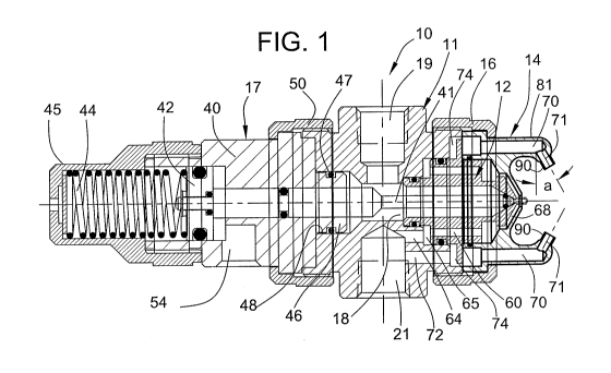
[0012] FIGURE 1 is a longitudinal section of an illustrative external mix air
assisted
spray nozzle assembly in accordance with the invention, taken axially through
the spray
nozzle assembly;
[0013] FIG. 2 is an enlarged fragmentary section of the spray tip and air cap
of the
illustrated spray nozzle assembly;
CA 02796352 2012-10-12
WO 2011/133342 PCT/US2011/031759
3
[0014] FIG. 3 is an end view of the nozzle body of the illustrated spray
nozzle
assembly;
[0015] FIG. 4 is a front perspective of the air cap of the illustrated spray
nozzle;
[0016] FIG. 5 is a front end view of the air cap shown in FIG. 4;
[0017] FIG. 6 is a side view of the air cap shown in FIG. 4;
[0018] FIG. 7 is a rear perspective of the air cap shown in FIG. 4;
[0019] FIG. 8 is a longitudinal section of an alternative embodiment of
external mix
air assisted spray nozzle assembly in accordance with the invention; and
[0020] FIG. 9 is a front perspective of the air cap of the spray nozzle
assembly shown
in FIG. 8.
[0021] While the invention is susceptible of various modifications and
alternative
constructions, certain illustrative embodiments thereof have been shown in the
drawings
and will be described below in detail. It should be understood, however, that
there is no
intention to limit the invention to the specific forms disclosed, but on the
contrary, the
intention is to cover all modifications, alternative constructions, and
equivalents falling
within the spirit and scope of the invention.
DESCRIPTION OF THE PREFERRED EMBODIMENTS
[0022] Referring now more particularly to FIG. 1 of the drawings, there is
shown an
illustrative external mix spray nozzle assembly 10 in accordance with the
invention. The
illustrated spray nozzle assembly 10 includes a nozzle body 11, a liquid spray
tip 12 at the
discharge end thereof, an air cap 14 mounted in surrounding relation to the
discharge end
of the nozzle body 11 by a retaining ring 16, and a control module 17 at an
end opposite
the spray tip 12 for controlling the liquid spray discharge from the spray
nozzle assembly.
The basic structure and mode of operation of the spray nozzle assembly are
known in the
art, for example, as shown in U.S. Patent 5,707,010.
[0023] The illustrated nozzle body 11, as depicted in FIGS. 1 and 3, has an
axial
liquid flow passage 18 and a plurality of radial fluid passages. The radial
passages
include a liquid inlet port 19 for connection to a supply liquid to be sprayed
and
communicating with the liquid flow passage 18, an atomizing air inlet port 20
radially
offset from the liquid inlet port 19 (FIG. 1) for connection to a pressurized
air source or
other pressurized fluid for assisting in atomization of the liquid to be
sprayed, and a fan
CA 02796352 2012-10-12
WO 2011/133342 PCT/US2011/031759
4
air inlet port 21 also for connection to a pressurized air source for
assisting in direction
and form of the discharging liquid spray.
[0024] For controlling liquid flow and discharge through the liquid passage
18, the
control module 17 may be one of a plurality of standardized spray control
modules or
accessories that can be quickly and easily interchangeably mounted on the
nozzle body 11
for enabling more versatile use of the spray nozzle assembly for particular
spray
applications. The illustrated control module 14 includes a body member 40 that
carries a
shut-off valve needle 41 of a conventional type for reciprocating movement
with respect
to the spray tip 12. The valve needle 41 has a piston assembly 42 at its
opposite end
which is biased in a valve closing position by a spring 44 retained within a
cap 45
threadedly engaged with an upstream end of the body 40. The body 40 has a
downstream
relatively small diameter cylindrical hub portion 46 which carries an O-ring
47 that is
removably positionable within an upstream cylindrical bore 48 of the nozzle
body 11 with
a threadless union. For releasably securing the control module 14 in the
mounted
position, a retainer ring 50 is provided which threadably engages an upstream
threaded
hub portion 51 of the nozzle body 11.
[0025] During operation, for axially moving the valve needle 41 to an open
position
(to the left as viewed in FIG. 1) against the force of the spring 44, control
drive air or
some other fluid is supplied via an inlet port 54 of the module into a
cylinder adjacent a
forward side of the movable piston 42. As is known in the art, the control
fluid, i.e.,
compressed air, may be controlled externally, such as by solenoid actuated
valves, for
controlling sequential opening of the valve needle 41.
[0026] The spray tip 12 in this case has a forwardly extending nose portion 60
which
defines a liquid discharge orifice and which extends into and through a
central opening 61
of the air cap 14 for defining an annular air discharge orifice 62 through
which atomizing
air directed to the atomizing air inlet 20 discharges (FIG. 2). The atomizing
air inlet 20 in
this case communicates with a longitudinal passage 64 in the nozzle body,
which in turn
communicates with an annular passage 65 defined between the spray tip 12 and
nozzle
body 11, which in turn communicates with a plurality of longitudinal
passageways 66
through the spray tip 12, and in turn through a downstream conical passageway
68 that
communicates with the annular discharge orifice 62. The air cap 14 further has
opposed
longitudinal passages 70 which communicate with respective angled passages 71
through
which fan air directed from the fan air inlet 21 discharges to assist in
forming of the
CA 02796352 2012-10-12
WO 2011/133342 PCT/US2011/031759
discharge spray pattern. The fan air in this case communicates from the fan
air inlet 21
through a longitudinal passage 72 in the nozzle body 11, an annular chamber 74
between
the spray tip 12 and nozzle body 11, and the longitudinal and angled air cap
passages
70,71.
[0027] In accordance with the invention, the air cap angled fan air
passageways are
defined by tubular extensions of the air cap that minimize both fine particle
accumulation
around the fan air discharge orifices and pressurized air operating
requirements. The
illustrated air cap 14 has an upstream cylindrical side wall 78 which defines
a transverse
retention flange 79 and a smaller diameter forwardly extending cylindrical
base 80 with a
pair of ears or projections 81 extending forwardly from diametrically opposed
sides of the
base 80. The projections 81 in this case are defined in part by opposed
portions of the
cylindrical base 80, opposed tapered side walls 82, and opposite inwardly
extending
recesses 84. The tapered side walls 82 and recesses 84 further define a
central air cap end
face 84 in elevated relation to the recesses 84, which in this case has a
relatively small
rectangular shape, through which the central air cap opening 61 communicates.
[0028] The angled fan air passage defining tubular extensions of the air cap
14 in this
case are tubular members 90 that communicate with the respective longitudinal
air cap
passageways 70 and extend in inwardly and forwardly directed relation to the
air cap end
face 84. While the tubular members 90 in the illustrated embodiment are
integrally
formed with the air cap 14, alternatively, separate tubular members may be
fixedly
mounted within the projections. The tubular members 90 preferably extend a
distance
from the air cap projections 81 corresponding at least to the diameter of the
angled
passageways 71 and have a radial wall thickness no greater than 1/4 the
diameter of the
angled passageways 71. In the illustrated embodiment, the tubular members 90
have a
wall thickness of about 1/6 the diameter of the angled passageways 71.
[0029] In keeping with the invention, the angled passageways are oriented at a
relatively steep angle to the discharging liquid flow stream for maximizing
impingement
and atomization of the discharging liquid at lower air pressures and air
volume for further
minimizing material buildup about the fan air discharge orifices. In the
illustrated
embodiment, the angled fan air passages 71 are oriented at an angle a of about
30 with
respect to a line perpendicular to the axis of the discharging atomized liquid
flow stream.
Such relatively steep angle facilitates impingement of the discharging fan air
flow stream
while enabling lower air operating pressures and volume which otherwise can
generate
CA 02796352 2012-10-12
WO 2011/133342 PCT/US2011/031759
6
and disperse fine particles onto the exposed air cap surfaces. Such relatively
steep
impingement angle of the fan air streams, together with the relatively small
surface areas
about the fan air discharge orifices, effectively prevent particle buildup
that can impede
reliable operation of the spray nozzle assembly. Due to the small surface area
about the
fan air discharge orifices, however, in some applications the angled fan air
passages 71
may be oriented at greater angles, up to 45 , with respect to the discharging
liquid flow
stream.
[0030] Referring to FIGS. 8 and 9, there is shown an alternative embodiment of
spray
nozzle assembly in accordance with the invention, wherein items similar to
those
described above have been given similar reference numerals. In this case, the
air cap
tubular members 90, which define the angled air passageway 71, are formed with
transverse V-shaped cuts 95 that extend in a direction perpendicular to the
plane of the
opposed air cap projections 85 and tubular members 90. Such transversely
oriented V-
shaped cuts 95 enable the fan air to spread out into a larger jet pattern that
softens the
impact of the fan air on the discharging atomized liquid flow stream for
further
minimizing the generation and direction of fine liquid particles onto exposed
surfaces of
the air cap.
[0031] From the foregoing, it can be seen that the present invention provides
an
improved external mix air atomizing spray nozzle assembly adapted for more
efficient
spraying of highly viscous liquid materials. The spray nozzle assembly
substantially
reduces or eliminates undesirable buildup of sprayed materials onto externally
exposed
faces of the liquid spray tip and air cap. It unexpectedly achieves such
enhanced
performance by minimizing surface areas and low pressure zones about the fan
air
discharge orifices which otherwise can entrain fine particles and draw them
into contact
with the air cap surfaces. The air cap further can be efficiently operated at
lower air
pressures and air volumes for further minimizing undesirable buildup of
material on
exposed surfaces of the air cap.