Note: Descriptions are shown in the official language in which they were submitted.
CA 02796386 2012-10-12
WO 2011/133820 PCT/US2011/033501
LIQUID COOLED LED LIGHTING DEVICE
Cross Reference to Related Applications
[001] This application claims the benefit of priority under 35 U.S.C. Section
119(e) to
U.S. Provisional Application Ser. No. 61/438,389, filed February 1, 2011 and
Provisional
Application Ser. No. 61/327,180, filed April 23, 2010, which are fully
incorporated by
reference herein.
Field of the Invention
[002] The present invention relates to a lighting device and more particularly
to an
LED lighting device.
Background of the Invention
[003] For many illumination applications in LED (light emitting diode)
illumination or
lighting, an important issue is the removal of heat generated from an LED
lighting
element of an LED chip. Traditionally, LED chips have been mounted on a metal
substrate and the substrate is mounted on a heatsink with cooling fins. A fan
can then
be used to blow air over the heatsink fins to cool the LED chip.
[004] However, due to the relatively large distance between the LED chip and
the
heatsink fins, the cooling efficiency is usually low. As a result, the LED
junction operates
at higher temperatures, which reduces the light output and lifetime of the LED
chip.
[005] Therefore, it would be desirable to provide an LED light device and
method of
more efficiently cooling the LED lighting element.
Summary of the Disclosure
[006] According to one aspect of the present invention, a liquid cooled LED
lighting
device includes a sealed housing having a transmissive aperture and an LED
element
contained in the housing. The LED element has an emitting area that emits
light for
transmission through the aperture. Cooling liquid is contained in the housing
to disperse
heat generated by the LED element. Preferably, compressible material enclosed
in an
enclosure is positioned within the housing and outside of the optical path of
the emitted
light. The enclosure containing the compressible material compresses in
response to
expansion of the cooling liquid as it absorbs heat from the LED element.
1
CA 02796386 2012-10-12
WO 2011/133820 PCT/US2011/033501
[007] Advantageously, the cooling liquid and compressible material act to more
efficiently cool the LED element, thereby providing higher light output and
increased
lifetime. At the same time, use of the compressible material in the housing
allows the
housing to be made of a completely sealed rigid package.
[008] According to another aspect of the present invention, a liquid cooled
LED
lighting device includes a sealed housing having a recycling reflector. The
recycling
reflector has a reflective surface such that the LED light impinging on the
reflective
surface reflects back to the emitting area of the LED element. The cooling
liquid and
compressible material contained in the housing act to disperse heat generated
by the
LED element.
[009] According to another aspect of the present invention, a liquid cooled
LED
lighting device includes an LED element which is attached to the outside of
the sealed
housing. The cooling liquid and compressible material contained in the housing
act to
disperse heat generated by the LED element.
Brief Description of the Drawings
[0010] FIG. 1 shows an exemplary LED lighting device according to an
embodiment of
the present invention.
[0011] FIG. 2 shows an LED lighting device having a recycling reflector.
[0012] FIG. 3A shows an LED array of four LED elements with at least one
symmetrically arranged colored pair.
[0013] FIG. 3B shows an LED array of six symmetrically arranged LED elements.
[0014] FIG. 4 shows a liquid cooled LED lighting device invention in which the
light
output is recycled to allow higher output intensity according to an embodiment
of the
present invention.
[0015] FIGS. 5A-5E shows various types of enclosures that can be used to
enclose
compressible materials according to the present invention.
[0016] FIG. 6A shows an LED lighting device having a pump according to an
embodiment of the present invention.
[0017] FIG. 6B shows an LED lighting device having a pump and an LED element
in
contact with a cooling liquid according to an embodiment of the present
invention.
[0018] FIG. 7 shows an LED lighting device having an external pump according
to an
embodiment of the present invention.
2
CA 02796386 2012-10-12
WO 2011/133820 PCT/US2011/033501
Detailed Description of the Invention
[0019] FIG. 1 shows an exemplary LED lighting device according to one
embodiment
of the present invention. The LED lighting device 2 includes an LED package 4,
heatsink 5, and cooling liquid 9.
[0020] The LED package 4 includes at least one LED chip 10 which is typically
an LED
element having an emitting area that emits light and a substrate 12 on which
the chip is
mounted. The emitting area includes an optional transparent window 7 that
protects the
LED chip 10. The heatsink 5 is attached to the substrate 12 to carry heat away
from the
LED chip 10. Such LED packages, for example, are available from Luminus
Devices,
Inc. of Billerica, Massachusetts.
[0021] Cooling liquid 9 contained in a liquid sealed housing is positioned in
close
proximity to or near the LED chip 10. In FIG. 1, the boundary of the housing
containing
the cooling liquid is not shown as it can be used in many different
applications that use
different types of housings. Preferably, the cooling liquid 9 is in direct
contact with the
LED chip 10 (i.e., the LED semiconductor itself or the window 7) so that any
heat
generated by the chip will be carried away by the liquid immediately with very
little heat
resistance. In the case of FIG. 1, the cooling liquid 9 is in direct contact
with the
transparent window 7 of the chip. In cases where the transparent window 7 is
absent,
the cooling liquid 9 will be in direct contact with the LED semiconductor
itself.
Preferably, the cooling liquid 9 has low thermal expansion, high heat
conductivity,
chemically inert, and electrically insulating characteristics. One such liquid
is a
perfluorinated liquid called FluorinertTM available from 3M Company of St.
Paul,
Minnesota. Other lower cost liquids can be mineral oil, paraffin or the like.
[0022] FIG. 2 shows an LED lighting device with a recycling reflector as
disclosed in
applicant's earlier filed application number 13/077,006, filed March 31, 2011,
which is
incorporated herein by reference. The LED lighting device includes an LED
package 4,
a driver circuit 3 for driving the LED chips 10, a recycling reflector 6 such
as a recycling
collar positioned in front of the LED chip and a transmissive aperture 8
through which
the LED light passes.
[0023] The LED chips/elements 10 can be a single chip or multiple chips of
white
color, single color, or multiple color. For particular applications, they can
be arranged
such that the optical axis 16 of the transmissive aperture 8 of the recycling
reflector 6
goes through the center 20 (see FIG. 3) of the LED elements and the center is
also
3
CA 02796386 2012-10-12
WO 2011/133820 PCT/US2011/033501
substantially at the proximity of the center of curvature of the recycling
reflector. The
LED elements 10 are preferably arranged in the same plane and closely
positioned to
minimize any space between any two emitting areas of the LED elements. The LED
elements 10 can emit light of a single color such as red, green and blue or
emit white
light. The emission angle is typically 180 degrees or less.
[0024] The recycling collar 6 is curved in a concave manner relative to the
LED
element 10. The inner surface 14 is a reflective surface such that the LED
light that
impinges on the inner surface is reflected back to the light source, i.e., LED
elements.
The reflective surface can be provided by coating the exterior or interior
surface of the
collar 6 or by having a separate reflective mirror attached to the collar.
According to a
preferred embodiment, the recycling collar 6 is spherical in shape relative to
the center
20 of the LED elements 10 such that the output is reflected back to itself
with unit
magnification. Thus, it is effectively an imaging system where the LED
elements 10 form
an image on to itself. Advantageously, substantially all LED light that
impinges on the
inner spherical reflective surface 14 is reflected back to the light source,
i.e., emitting
areas of the LED elements 10.
[0025] As persons of ordinary skill in the art can appreciate, any LED light
that does
not pass through the transmissive aperture of a conventional illumination
system is lost
forever. However, by using the curved reflective surface 14, the LED lighting
device of
the present invention allows recovery of a substantial amount of light that
would have
been lost. For example, in an illumination system whose transmissive aperture
size
captures about 20% of emitted light, the recycling collar 6 allows collection
of an
additional 20% of the emitted light. Advantageously, that is an improvement of
100% in
captured light throughput, which results in a substantial improvement in
brightness.
[0026] The LED in the present invention can be a single LED or an array of
LEDs. The
LED can be white, single color, or composed of multiple chips with single or
multiple
colors. The LED can also be a DC LED, or an AC LED.
[0027] FIG. 3 shows some of the LED chips that can be used with the present
invention. FIG. 3A shows an LED array 18 of four colored LED elements 10.
Specifically, the LED array 18 includes one red LED element R emitting red
color light,
one blue LED element B emitting blue color light arranged at opposite corners
and
symmetrically about the center 20, and two green LED elements G1,G2 emitting
green
color light arranged at opposite corners and symmetrically about the center 20
of the
LED array. The LED array 18 is arranged such that the optical axis 16 of the
recycling
4
CA 02796386 2012-10-12
WO 2011/133820 PCT/US2011/033501
reflector 6 passes through the center 20 and the center is also substantially
at the
proximity of the center of curvature of the recycling reflector 6.
[0028] While the LED array 18 is shown with four LED elements, the present
invention
can work with at least one LED element. Also, in the case of a pair of LED
elements,
while it is preferable that the LED elements in the pair emit the same color,
they can emit
different colors although the efficiency may be lower. Moreover, the size of
each LED
element in the array can be different from any other LED element.
[0029] It is to be noted that while each LED element 10 is shown as a square,
it can be
rectangular. Preferably, the total emitting area of the LED array 18 should
have the
same aspect ratio as the image to be projected. For example, to project a high
definition
television image whose aspect ratio is 9:16, the total emitting area of the
LED array 18
should have the same 9:16 dimension. Similarly, the dimension of the LED array
18 can
be, among others, 4:3, 1:1, 2.2:1, which are also popular aspect ratios.
[0030] In the embodiment of FIG. 3A, the two green LED elements G1,G2 are
imaged
on to each other. Specifically, any light from LED element G1 impinging on the
interior
reflective surface 14 is reflected back to the symmetrically positioned LED
element G2
and vice versa. For the symmetrically arranged same color LED elements to work
well,
the driver circuit 3 drives the same color LED elements (e.g., G1,G2)
simultaneously.
Thus, this arrangement provides high recycling efficiency. On the other hand,
light from
the blue LED element B is imaged onto the red LED element R and vise versa.
Thus,
the recycling efficiency is lower for these two colors.
[0031] In order to increase the efficiency with multi-colored LED elements, a
symmetric
configuration as shown in FIG. 3B can be used. In this embodiment, the red
chips (LED
elements R) are arranged symmetrically with respect to the center 20. As such,
the red
chips are imaged onto each other with high recycling efficiency. Similarly,
the blue chips
(LED elements B) and green chips (LED elements G) are also arranged
symmetrically
with respect to the center 20 and will be imaged onto each other with high
recycling
efficiency.
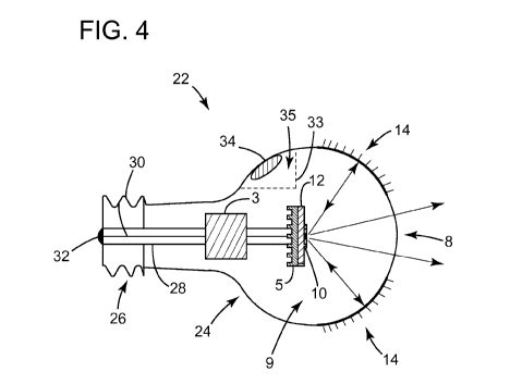
[0032] FIG. 4 shows a liquid cooled LED lighting device invention in which the
light
output is recycled to allow higher output intensity according to an embodiment
of the
present invention. In FIG. 4, the LED lighting device is an LED light bulb 22
having a
sealed housing/bulb 24 and a base 26. The sealed bulb 24 can be made of
plastic,
glass or metal.
CA 02796386 2012-10-12
WO 2011/133820 PCT/US2011/033501
[0033] An LED mount 28 is attached to the base 26 and provides the rigid
support
structure for attaching a control circuit 3, heat sink 5, substrate 12 and LED
chips 10
which are electrically connected to the control circuit. The substrate 12
supporting the
LED chip 10 is mounted on the heatsink 5. The LED mount 28 also has a conduit
for
carrying electrical wires from the control circuit to an electrical foot
contact 32 and screw
threaded contact 30. In operation, line voltage from the electrical contacts
30,32 is
converted to the desired level for the LED chip 10 by the control/driver
circuit 3.
[0034] Although FIG. 4 shows a light bulb having an Edison type threaded base
connector, any other LED lighting devices such as one having MR-16 type base
are also
suitable for use with the present invention.
[0035] The bulb 24 has an optically transparent transmissive aperture 8
through which
the emitted light from the LED chip 10 passes. The aperture 8 can be a simple
optically
transparent spherical window or can have a lens such as a focusing lens or
collimating
lens to obtain a desired output divergence.
[0036] The part of the bulb 24 above the substrate 12 is spherically shaped
relative to
the center of the LED chip 10 emitting area. A part of the spherical bulb
surface around
the transmissive aperture 8 is coated with reflective coating 14 for
reflecting the emitted
light back to the LED chip 10 light emitting area. This functions as the
recycling collar 6
as shown in FIG. 2.
[0037] According to the invention, the sealed light bulb 24 is filled with
cooling liquid 9
for heat sinking. Similar to FIG. 1, the sealed cooling liquid 9 is positioned
in close
proximity to or near the LED chip 10. As shown, the cooling liquid 9 is in
direct contact
with the LED chip 10 emitting area so that any heat generated by the chip will
be carried
away by the liquid immediately with very little heat resistance.
[0038] The LED chip 10 generates heat when emitting light. The heat in turn
heats the
cooling liquid 9 which expands in volume. Since the cooling liquid 9 is sealed
inside the
bulb 24, a relief is needed to prevent explosion due to expansion of the
cooling liquid.
As shown in FIG. 4, compressible material 34 is positioned inside the bulb to
absorb the
expanding volume of the cooling liquid 9 by compressing. In the embodiment
shown,
the compressible material 34 is immovably positioned and is outside of the
optical path
of the emitted light so that it does not interfere with the light being
transmitted through
the transmissive aperture 8. If not, the compressible material 34 may travel
into the
optical path of the light and create distortions and shadows in the light
exiting the
aperture 8 and may also reduce the light output.
6
CA 02796386 2012-10-12
WO 2011/133820 PCT/US2011/033501
[0039] In FIG. 4, the compressible material 34 is attached to the inner
surface of the
bulb 24. Alternatively, the compressible material 34 can be immovably attached
to the
LED mount 28, heat sink or other parts within the bulb 24 so long as the
material is
positioned outside of the optical path of the emitted light. In some
embodiment the
compressible material is contained in a sealed enclosure as shown in FIG. 4.
[0040] The compressible material as shown in FIG. 4 is a pocket of air. The
air pocket
is contained inside a small sealed balloon enclosure. As the pressure inside
the bulb 24
increases, the air pocket 34 will reduce in volume, relieving the pressure
inside the light
bulb.
[0041] Instead of positioning the compressible material 34 inside the housing
24, a
part of the housing can be made of flexible material such as rubber so that it
can expand
as the cooling liquid 9 expands. However, this is not a preferred solution
because it is
difficult to maintain a seal between the flexible material and the rigid
housing. Thus,
positioning of the compressible material 34 inside the housing 24 according to
the
present invention allows the housing to be made entirely of rigid, non-
expanding material
which is completely sealed, thereby improving the reliability and durability
of the LED
lighting device.
[0042] In an alternative embodiment, the compressible material 34 such as air
is
contained in an enclosure and is confined within an internal chamber 35
defined by an
internal wall 33 having openings so that the fluid 9 flows freely
therethrough. In this way,
the compressible material 34 do not need to be immovably positioned.
Preferably, the
wall 33 and therefore the compressible material 34 and its enclosure are
outside of the
optical path of the emitted light.
[0043] Although the embodiment of FIG. 4 shows air as the compressible
material, any
other types of gas, which by nature are compressible, such as nitrogen can be
used. In
fact, even vacuum can be used so long as the enclosure is sufficiently rigid
to withstand
the force of vacuum, yet sufficiently flexible to compress due to the external
pressure of
the expanding cooling liquid 9.
[0044] FIG. 5 shows various types of enclosures for enclosing compressible
materials
according to the present invention. FIG. 5A is a section of tubing containing
air with both
ends sealed. The tubing can be rubber, silicone, plastic or the like.
[0045] The shape of the enclosure can be cylindrical as shown in FIG. 5A,
spherical as
shown in FIG.5B, toroidal as shown in FIG. 5C, a flat cavity such as a disk as
shown in
7
CA 02796386 2012-10-12
WO 2011/133820 PCT/US2011/033501
FIG. 5D, or the like. The air pocket can be independent of the package, or can
be
attached to the package, or can be integrated with the package.
[0046] As shown in FIG. 5E, the compressible material 34 can be a collection
of small
air pockets packed together as a piece of "foam". Such materials provide the
necessary
volume of gas required that is easy to handle and that can be cut to size as
needed.
The foam material can be found in packing cushion materials, for example.
Materials
that make up these foams could be vinyl, silicone, rubber, etc. The gas inside
the
pockets can be air, nitrogen, or the like.
[0047] To enhance the efficiency of cooling and heat sinking, a pump 38 can be
added
to circulate the cooling liquid inside the housing 24. The pump 38 quickly
moves away
the hot liquid near the LED chips 10 and replaced it with cooler liquid,
thereby increasing
the efficiency of cooling in order to reduce the junction temperature of the
LED chips.
[0048] In a preferred embodiment, the pump 38 is an ultrasonic pump.
Ultrasonic
signal is used to drive a transducer such that it generates acoustic waves in
the cooling
liquid 9. The configuration of the pump 38 is such that the acoustic wave
produces a net
flow of liquid.
[0049] FIG. 6A shows an LED lighting device with such a pump. The liquid
sealed
housing 24 contains an ultrasonic pump 38 having an inlet 40 on one side and
an outlet
42 on another side. The ultrasonic pump 38 is driven by an ultrasonic driver
circuit 44
located outside the housing 24 that generates an ultrasonic drive signal. In
FIG. 6A, the
substrate 12 and LED chip 10 attached to the substrate are mounted to the
outer surface
of the housing 24 instead of being attached to the inside of the housing as
shown in FIG.
4. Cooling fins 50 are attached to the housing 24 to remove heat from the
cooling liquid
9. Preferably, the housing 24 in FIG. 6A is made of heat conductive material
such as
metal or metal alloy.
[0050] The air pocket 34 in FIG. 6A is similar to that of FIG. 4, except that
since the
LED chip 10 is attached to the outside of the housing 24, the air pocket does
not have to
be immovably attached to the housing 24.
[0051] FIG. 6B shows an alternative LED lighting device in which the LED chip
10 and
internal heat sink 5 are immersed in the cooling liquid 9 for effective
cooling. The
compressible material 34 is similar to that of FIG. 4 and is attached to the
interior surface
of the liquid sealed housing 24 away from the optical path of the LED chipl0.
Fins 50
are attached to the housing 24 to remove heat from the cooling liquid 9.
Preferably, the
housing 24 in FIG. 6B is made of heat conductive material such as metal or
metal alloy.
8
CA 02796386 2012-10-12
WO 2011/133820 PCT/US2011/033501
[0052] The heatsink 5 is attached to the interior surface of the housing 24 so
that the
heat from the heatsink can be redistributed throughout the housing. The base
26
attached to the housing 24 couples electrical wires from the LED chip 10 and
pump 38 to
connectors 46. The light emitting from the LED chip 10 is transmitted through
the
aperture/optical window 8.
[0053] FIG. 7 shows an LED lighting device according to another embodiment of
the
present invention. An array of LED chips 10 and substrate 12 are mounted on a
heatsink 5 attached to the interior surface of the housing 24. The
compressible material
34 is attached to the interior surface of the housing 24 and is positioned
outside of the
optical path of the emitted light. The housing 24 has an inlet 52 and outlet
54. A flow
tube 56 is coupled between the inlet 52 and outlet 54. Cooling fins 50 are
attached to a
portion of the flow tube 56 defining a cooling chamber 58. A pump such as an
ultrasonic
pump 38 is connected inline with the flow tube 56 to pump the cooling liquid 9
from the
housing 24 to the cooling chamber 58 for efficient heat sinking by the cooling
fins.
[0054] The above disclosure is intended to be illustrative and not exhaustive.
This
description will suggest many modifications, variations, and alternatives may
be made by
ordinary skill in this art without departing from the scope of the invention.
Those familiar
with the art may recognize other equivalents to the specific embodiments
described
herein. For example, although the present invention is shown with a recycling
reflector,
it can be used without the recycling of light. Also, while the present
invention has been
shown in the context of an LED as the light source, it can be used with any
light source
that generates a significant amount of heat in operation. For example, the
present
invention can be used with laser, arc lamp, or the like. The principles of the
present
invention can also be applied to any other non-optical applications where heat
is
generated such as power transistors, microprocessors, inductors, rectifiers
and
transformers. Accordingly, the scope of the invention is not limited to the
foregoing
specification.
9